The DC transformer section started life as an R&D platform (named inv48) for transformer design. Hence, it's very simple and beyond current limiting doesn't incorporate features to protect it from or manage its environment (e.g. no thermal management, regulation of auxiliary supply, etc.).
It's unique feature is the use of a Bluetooth module to provide a primitive console that was used for control & data acquisition. Through the use of a terminal emulator on a PC the unit can be start/stopped, operating parameters viewed & changed, etc. Added benefits are galvanic isolation - very beneficial when working with high voltages - and no cable fuss.
This section shares a common lineage with the buck: both use the PIC16F1769 MCU, gate drive & switching MOSFETs, auxiliary supply scheme, and some firmware. Pulse-pulse current limiting is provided by low side current sense resistors on each leg of the bridge.
The bridge is a conventional H configuration using MOSFET transistors and bootstrap-based high side gate drives. The original design included an output LC filter and opto-isolator based feedback for the voltage control loop. The transformer primary used a single winding and the secondary a center-tap for full wave rectification.
Eventually work began on the digital sine evaluator and a high voltage DC source was needed to power it. Inv48 was adapted for this purpose. The output LC filter and control loop were removed, a new transformer (TDK/EPCOS RM10 core, N41 ferrite) was built with a single winding secondary that produced ~ 160V with 12V DC on the primary, and updates to the firmware. This set the stage for its final transformation.
As used in the TS50 project, inv48 functions as a glorified DC transformer. It operates at a fixed frequency of 50kHz and fixed duty cycle of 95% for each side of the bridge. In addition to the previously mentioned modifications, the opto-isolator was repurposed to issue a logic 'turn-on' command to the sine section once the DC transformer was running.
To be of some value in the real world, the current sense needed some adjustment since the original design was for peak currents under 10A. The TS50 supports 50W RMS loads, no problem. But even a silly 40W incandescent bulb could generate primary currents in excess of 60A! Note that the steady state current is ~ 333mA RMS.
Here's the math: the cold resistance of a 40W bulb @ 25C is ~ 25Ω. 120VAC RMS / 25 = 4.8A. Reflected back to the primary of the DC transformer, with a ratio of 14:1, 4.8 * 14 = 67.2A. The instantaneous currents could be even higher depending on where the sine voltage waveform is at the instant of turn-on (the peak of the sine wave @ 120V RMS is 170V).
In practice, the primary doesn't see currents that high because the bulk capacitance on the HV supply sources it and it's of a duration measured in microseconds since the bulb's filament resistance increases rapidly (the impedance in the sine section's output inductor also limits instantaneous current). It is still, however, high: I've measured peaks exceeding 1.5A. So again, reflected to the primary 1.5 * 14 = 21A.
This peak demand will persist for several milliseconds, longer than the bulk capacitance on the primary can support, so the DC transformer must be able to support this for short durations (on the order of a few seconds).
The MOSFETs used in the bridge are capable of handling 60A ~ 100uS. The PCB is only 1 oz CU but for short durations not a concern, plus traces & ground planes are generous so that parasitic inductance doesn't cause glitches. The current sense resistors where changed to 10mΩ and higher power ratings to handle the peak & RMS currents.
The firmware was further modified for automated start (vs. requiring console input), input under & over-voltage limits, logic control of the sine section, and improved current limiting. Per the above's discussion, the current limit was set at 18A.
Current limiting employs an inner & outer control loop. The inner loop is hardware based (configured in firmware) and limits current pulse-pulse. The outer loop is a simple PI loop that shuts the bridge down if the condition persists. Clearing the condition requires console intervention or a power cycle.
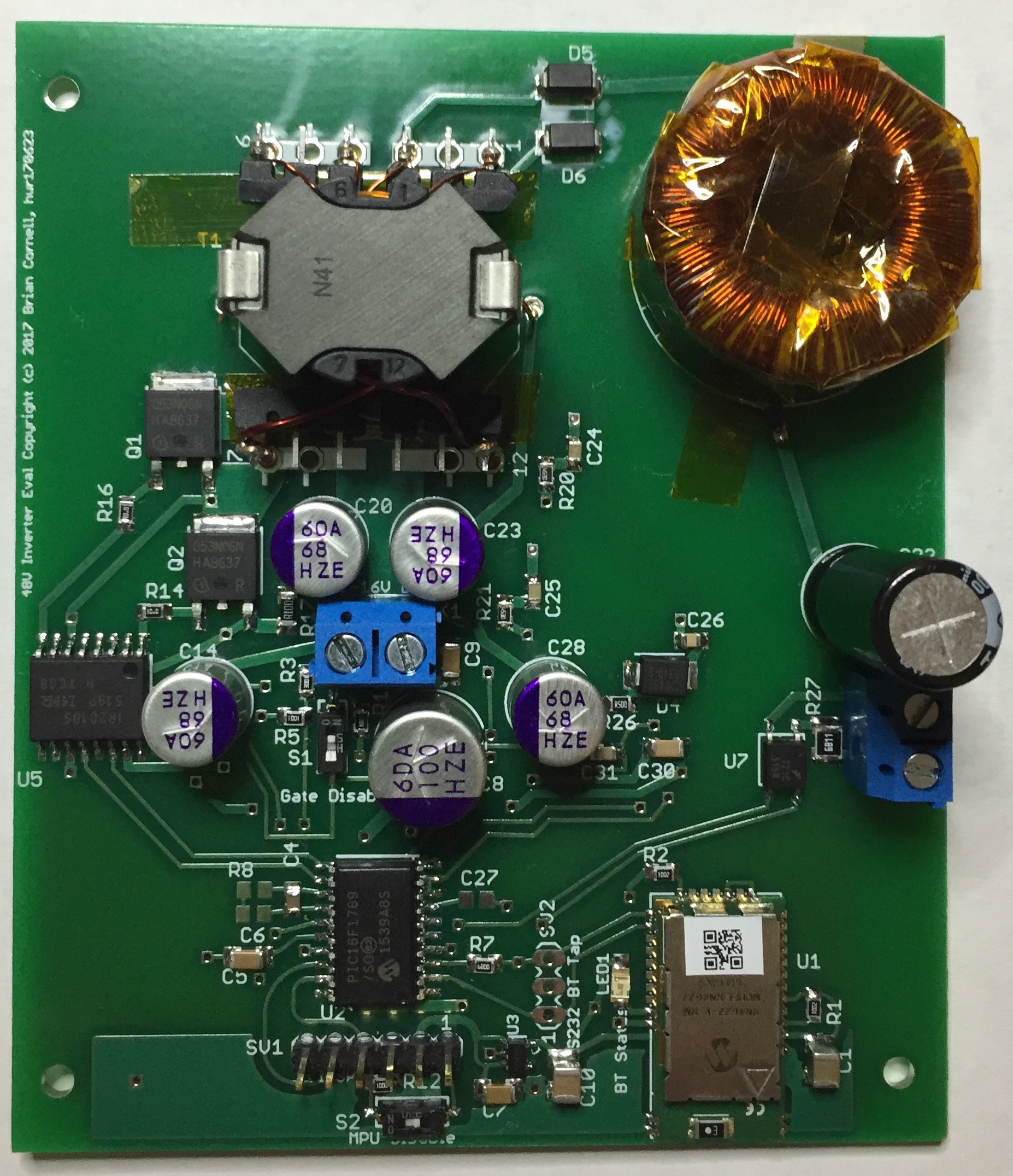
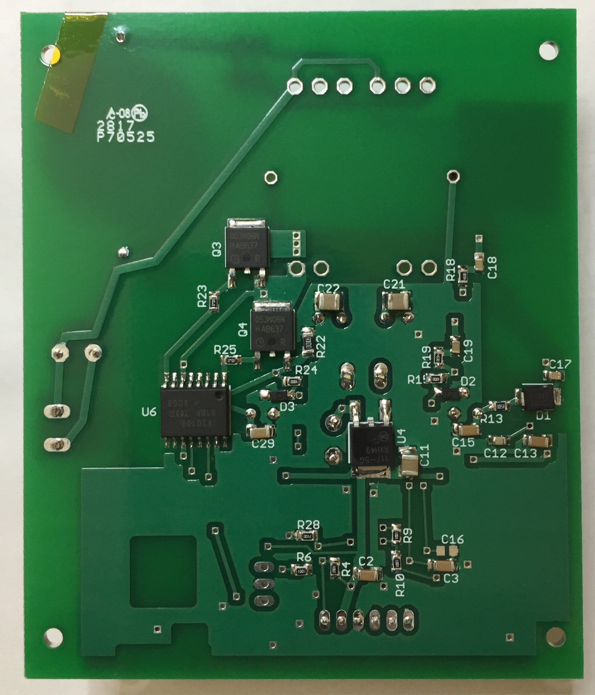
Pictures of the original unmodified unit:
Discussions
Become a Hackaday.io Member
Create an account to leave a comment. Already have an account? Log In.