 Keith
KeithI don't have the time or skills to write a program to do this with a nice user interface. I had to create the SVG file holding the tracing background by using a text editor. Fortunately I have been creating html files that way since the internet took off, and I can pick up the basics of similar descriptive file formats.
First attempt had many coordinates 'off grid'. I corrected them by copying them to a spreadsheet and rounding them off to the nearest multiple of the grid pitches. Obviously it is best to do this all in one go after all coordinates are in.
The board I used was laid out using red and green tape on Mylar film. Most are on 100, 50 or 25 thou grid, but a few are slightly off where there was some tight routing. Those soon became apparent when the corrected SVG was shown over the PCB scan. They had to be manually moved back off-grid.
The right way to avoid work is to have the PCB image scaled so that the holes are all on grid points, and set your vector graphics package to snap graphics to grid.
It took me about 12 hours to trace the tracks on this 100 x 160 mm board. Inventing the procedure and teaching myself about basic SVG took a lot of time but that should not need repeating. The work is very amenable to sharing across multiple sessions and multiple workers. You can see exactly what has already been done. Crowd working is possible, a group of people could trace small subsections, which could then be merged. Or people could take it in turns to work on the same file. For large boards, crowdworking might be the only way to do a job in a practical timescale.
SVG files describe 2-D geometric shapes, and have some features in common with programming languages. For example, you can describe a standard hole, then say a DIL16 socket is a an array of holes, then say draw a DIL16 socket in 32 places for an array of DRAM chips. In this way it is more efficient than a Gerber file, which would simply describe 512 holes.
Gerber files have one file per layer, and need Gerber viewer software. This is not included with internet browsers. There are gerber-to-svg tools and I will investigate them.
The first project image here is a screenshot of the rendered SVG. Hackaday does not accept SVG files there. You have to download and unzip the file.
I defined hole sizes and positions in inches, and board sizes in mm, because DIL packages are specified in inches and the board is specified as 100x160 mm. However, it seems that not everything can be defined in such units. Which is annoying, you would think that the standard would get away from the concept of a pixel. It works with virtual pixels, but didn't even nail down a pixel size from day one. First it was 90 pixels per inch, I don't know why they chose that number. Then they changed it to 96 pixels per inch, which really annoyed people who had created a lot of previous work. I found that SVG files that looked right on my Linux system were wrong on my Windows system.
I can guess why they did this. Typesetting was established long ago, in inches. People would want lines of text per inch. Each line would be a fraction of an inch; 1/2, 1/3, 1/4, 1/6, 1/8. These can be expressed with a common denominator. 36/72, 24/72, 18/72, 12/72, 9/72. So 1/72 of an inch was named a 'point', and the font sizes would be 36, 24, 18, 12, and 9 points. The number 96 is exactly 4/3 times 72, which makes it easier to calculate font sizes in pixels. just multiply by 4 and divide by 3, and you get 48, 32, 24, 16, and 12 pixels. 96 is also nearer the 100 dpi of the computer printer standards ... but not exactly equal.
96 dpi also makes it match the CSS standard.
Longer story here: http://wiki.inkscape.org/wiki/index.php/Units_In_Inkscape
In future, I think I will create SVGs with a scale of 100 grid points per inch, and apply scaling factors later. The kind of boards that need tracing most are old ones that were made when decimal inch...
Read more »
 Timo Birnschein
 Jarrett
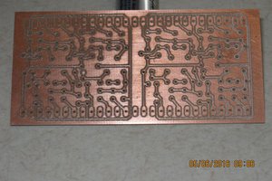
 agp.cooper
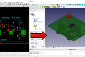
 Maurice
I worked on a supercomputer that had 19 layer circuit boards. It would be tough to create a SVG of them.