 Dimitris Xydas
… or more correctly, from CAD to reality, as it is time for 3D printing!
Initially, before getting my own 3D printer, I used Shapeways to print copies of some of the Robotis plastic brackets (they were hard to source online).
At one point I also calculated the costs for the custom 3D printed parts, by getting quotes from Shapeways. The basic parts required totalled to £1,000! Luckily I ended up getting a FlashForge Creator Pro 2017 soon after, so was able to print the structural parts at home for much cheaper.
Chassis parts
After first designing the initial version of each part in Fusion 360, I the made an update pass with some practical updates such as:
- adding fillets around the edges
- decreasing nut hole diameters by 0.2 mm in order to provide some material for self-tapping threads
- increased the tolerance of some slots by the same amount, to allow a tolerance for their connection to interlocking plastic tabs
- modifying the rear section to provide more rigidity to the central connection with the spine servo bracket, by adding a 90° tab to the rear underside aluminium base
Here are some images of the CAD models of the chassis parts:
| Foot Base | |
|---|---|
 |  |
 | 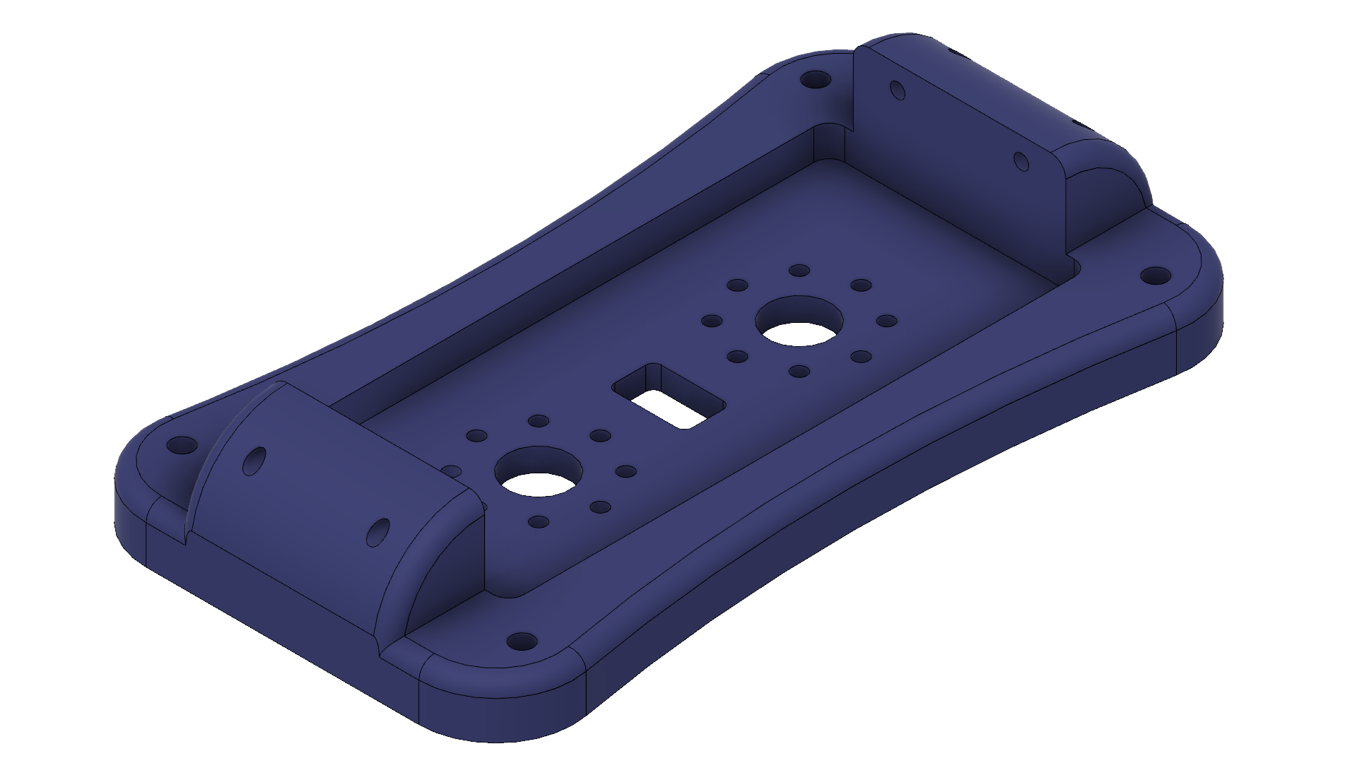 |
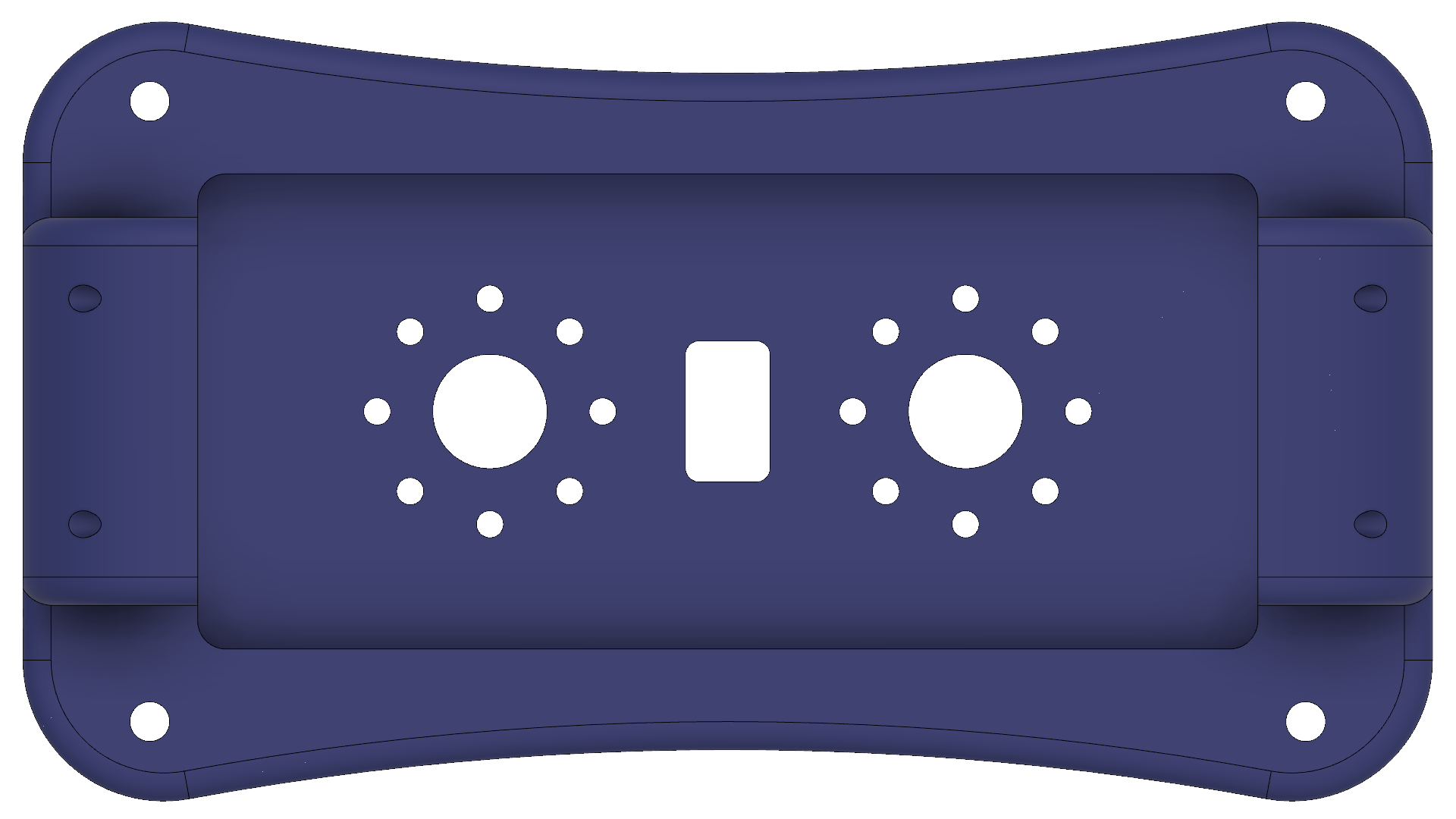
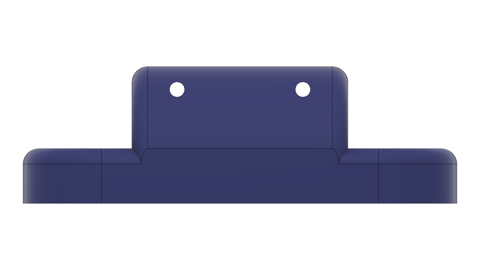
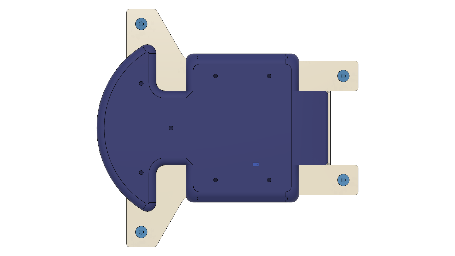
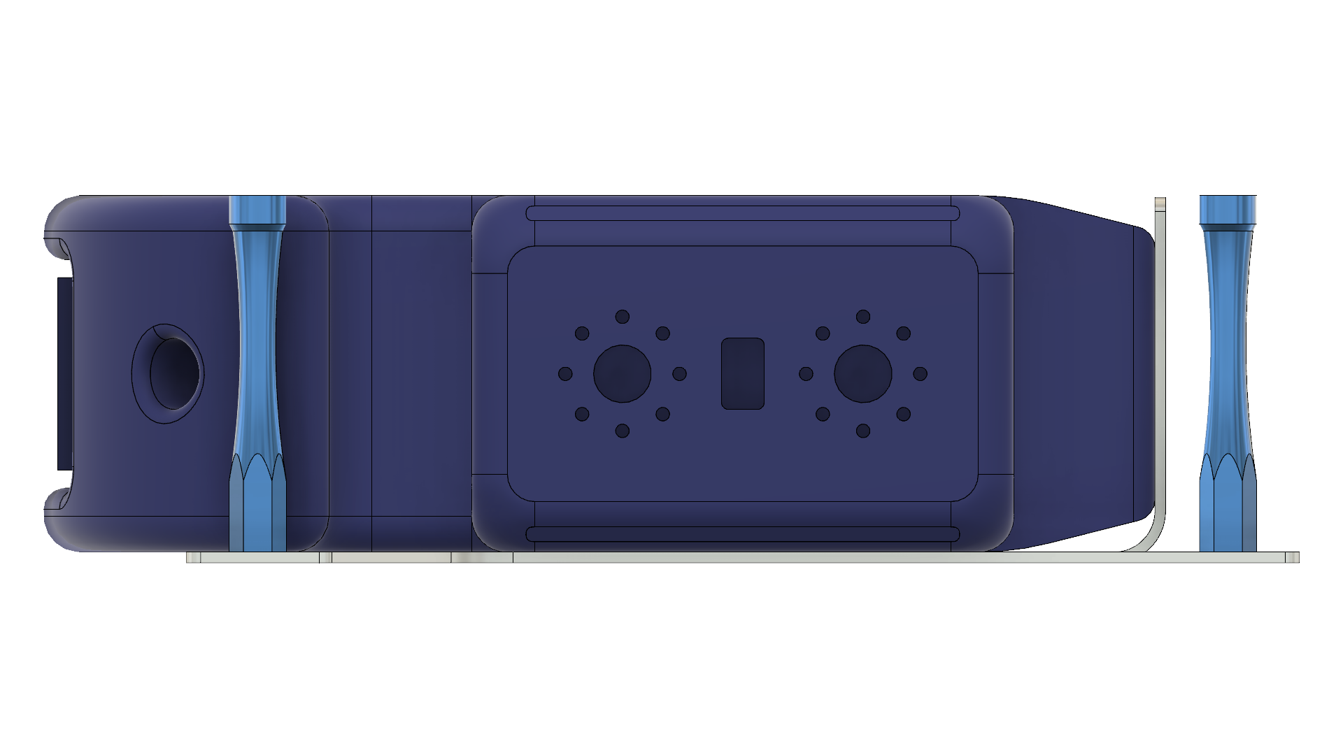
Front body assembly | |
|---|---|
 |  |
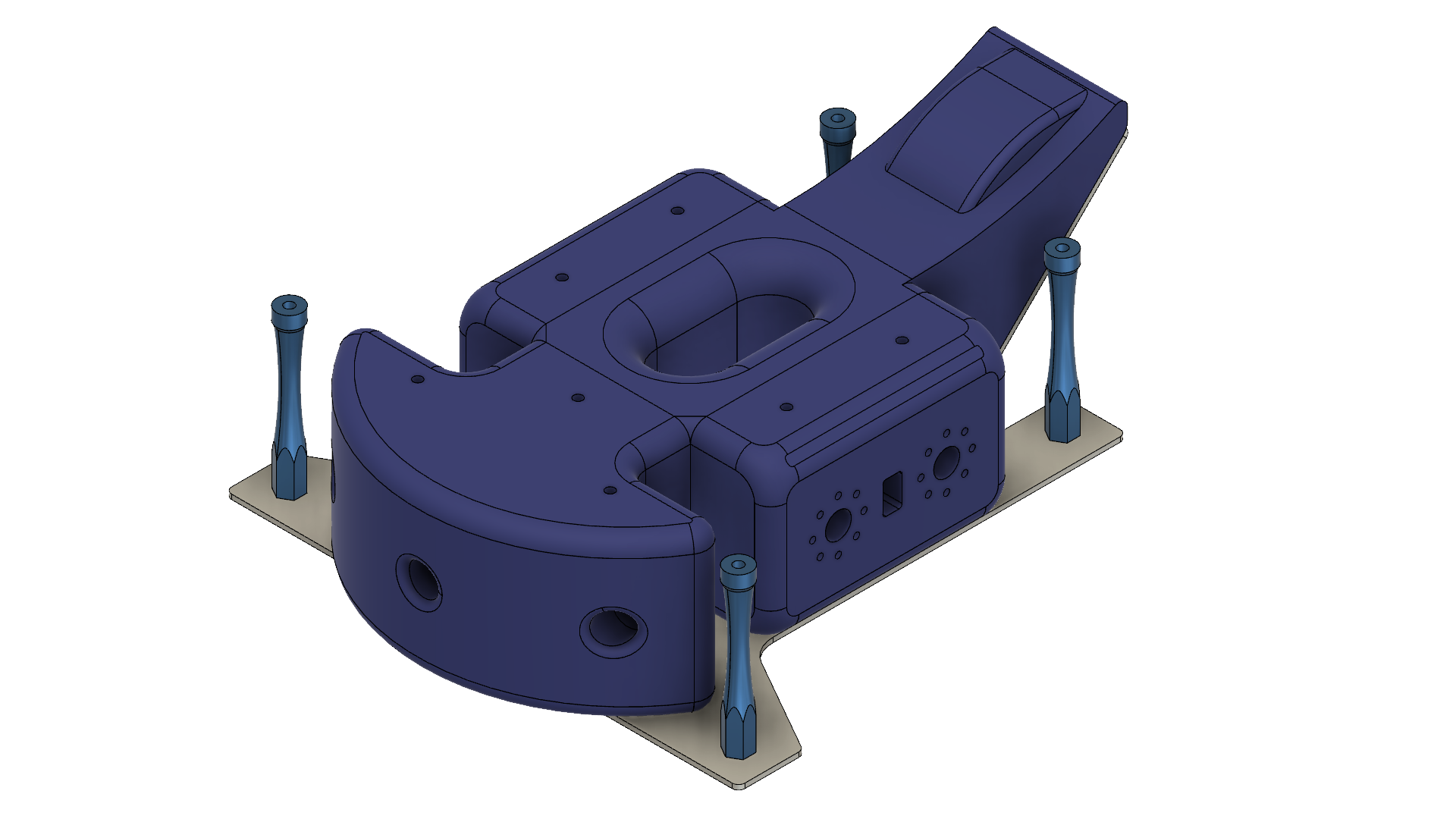 | 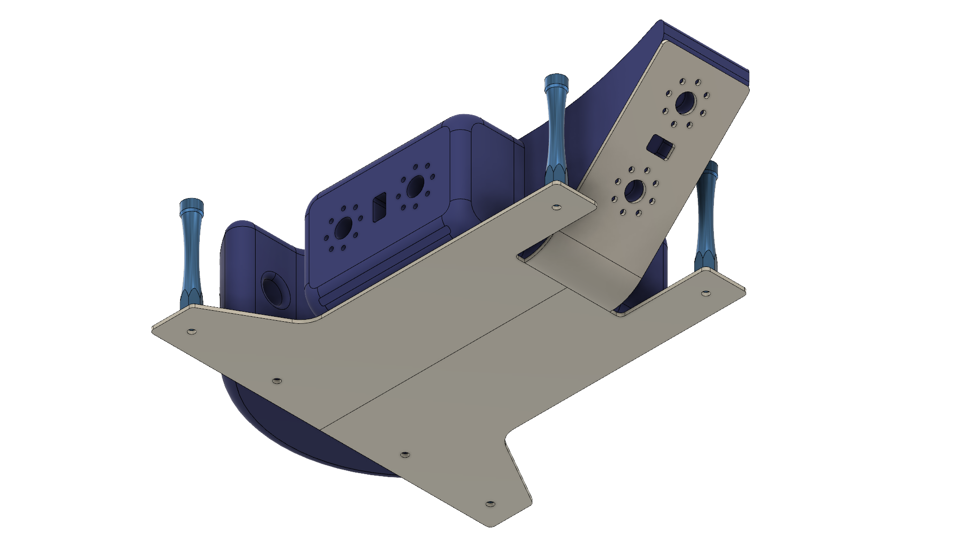 |
Rear body assembly | |
|---|---|
 |  |
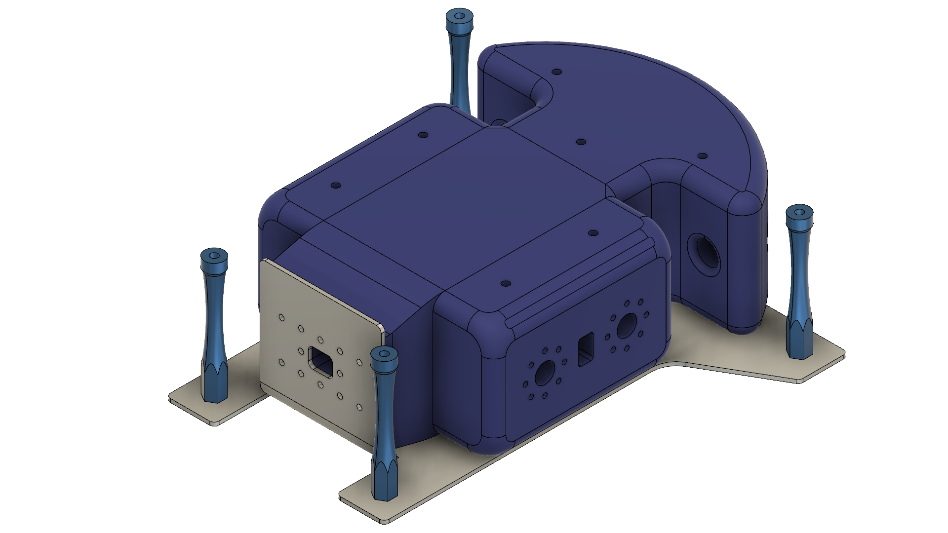 | 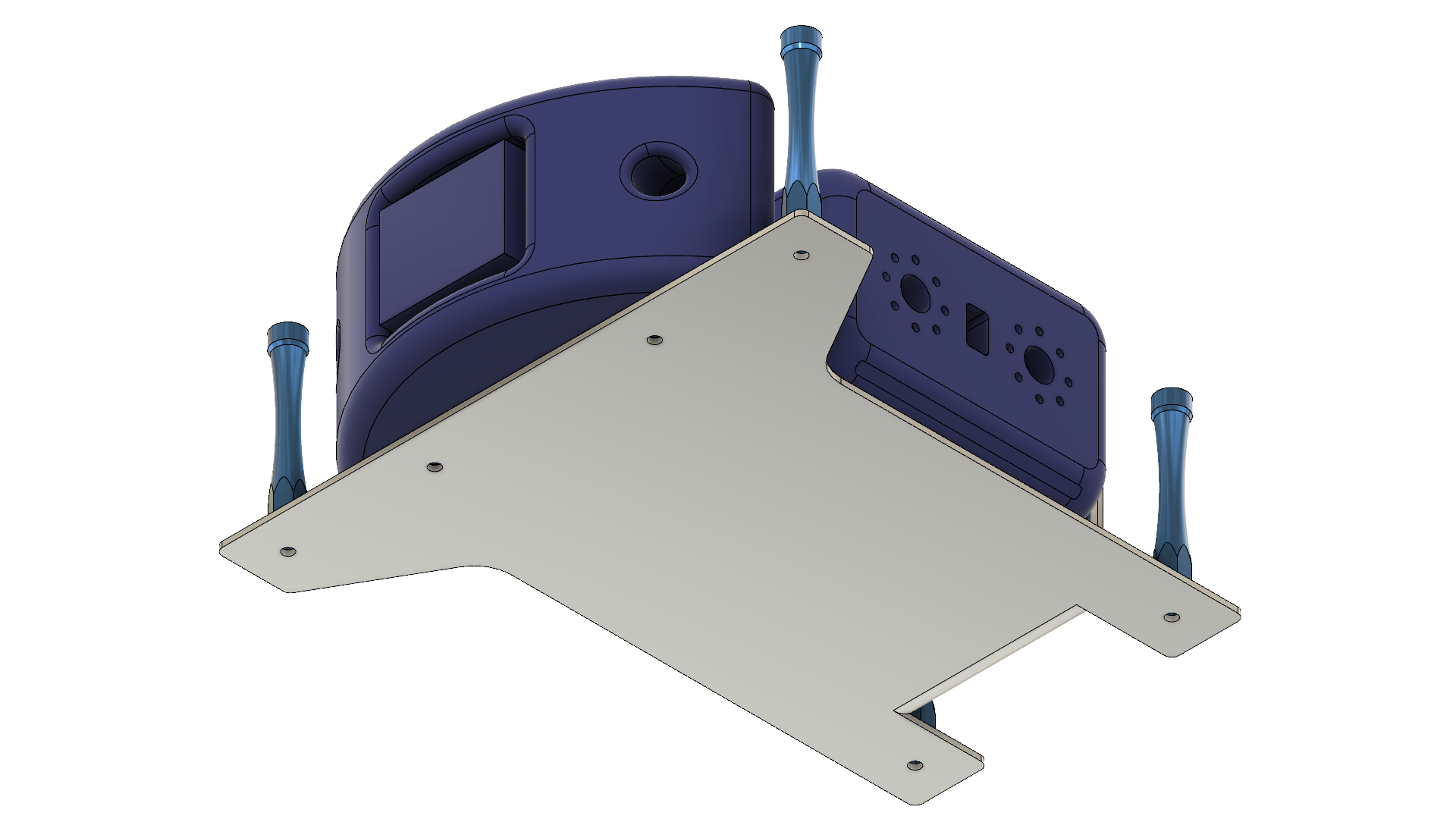 |
Printing
All parts were printed in PLA plastic.
The first part I started with was the foot base. I printed it with a 20% honeycomb infill. I didn’t add any intermediate solid layers, but might do so in other parts.
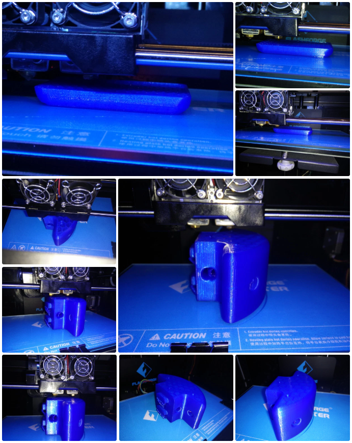
Each leg connects to a leg base bracket, which is the same design for all legs. The part was printed “upside-down” because of the orientation of the interlocking tabs. This meant that some support structure was needed for the holes. For the first print attempt I also added supports around the overhang of the filleted edge, along with a brim, but for the subsequent prints I didn’t bother with these, as the fillet overhang held fine without supports, and saved from extra filing/sanding down. These parts also used 20% infill.
For the front and rear “bumpers”, I reduced the infill to 10%.
For the larger part comprising of the central section of the front, the spine front bracket, I also used an infill of 10%. Due to the more complicated design that would have included many overhangs, I found it easier to cut the part lengthwise and print it as two separate pieces. These will be super-glued together after sanding.
Time-lapse GIFs and images of the printing process:

Front Bumper

Spine Front Bracket
Parts & Assembly
In terms of printing times, the foot bases and leg base brackets took about 3 hours each, the bumpers took around 4 hours each, and the two spine front bracket halves took about 7 hours combined, so total printing time is was fairly large!
The 0.2 mm clearance seems to work fine for self-threading the plastic with M2 size metal nuts, but was too large for some of the plastic-to-plastic interlocking tabs, possibly since this tolerance is close to the resolution limits of the printer (theoretically a 0.4 mm nozzle and 0.18 mm layer height). However after some filing and sanding down, all the plastic parts fit together nicely.
The resulting 3D prints before and after sanding:

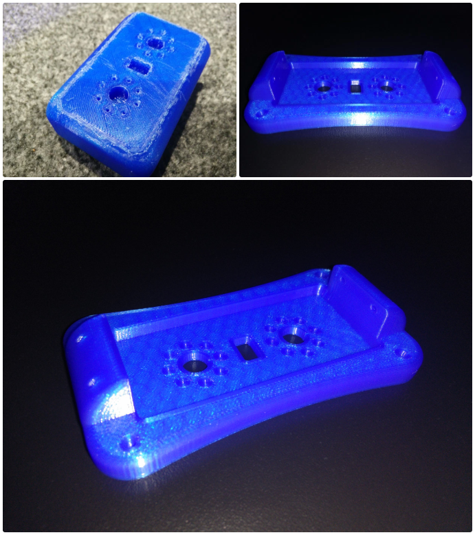
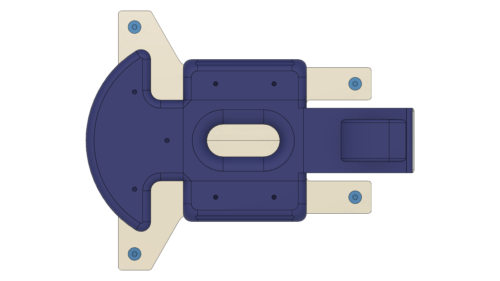
Finally, here are some images of how the chassis assembly shaped up, as well as the foot bases shown attached to the foot metal brackets. These fitted snug without any sanding, and all the holes aligned perfectly with the metal brackets, which was reassuring!
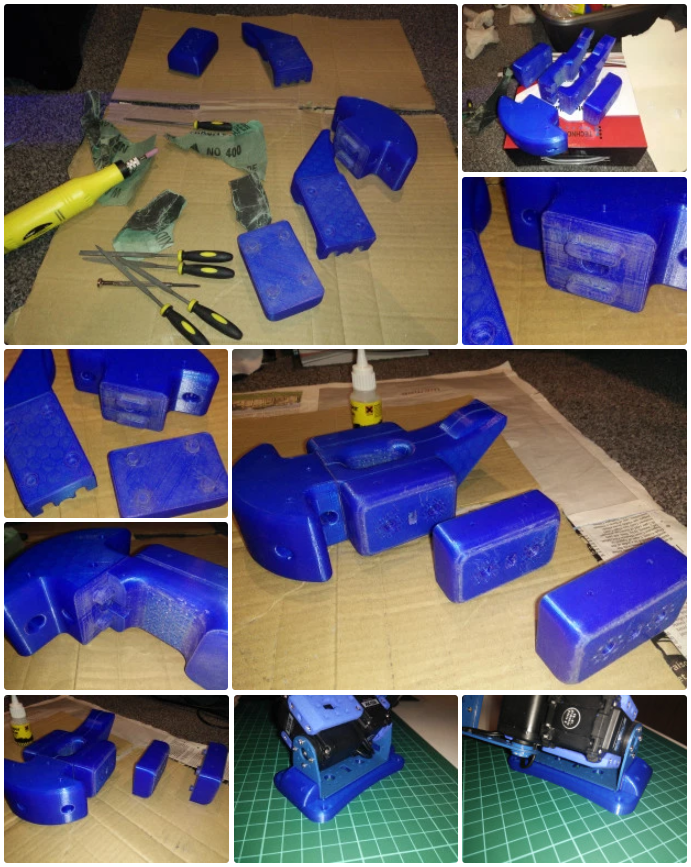
The next step was to glue the front bracket halves together, print the remaining parts, and paint everything.
Discussions
Become a Hackaday.io Member
Create an account to leave a comment. Already have an account? Log In.