 Dimitris Xydas
After 3D printing a few more plastic parts and cutting all the aluminium plates, the custom chassis was finally complete! Below are some notes on the remaining 3D parts and the metal plates.
More 3D printed parts and painting
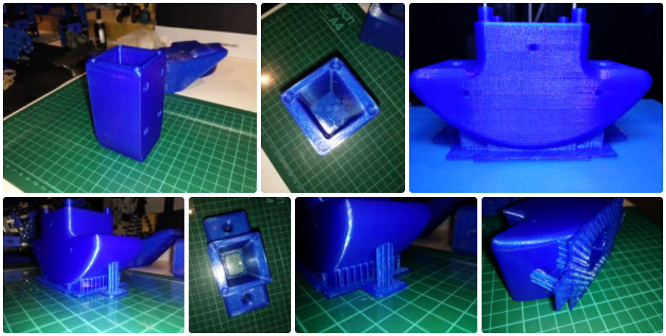
I printed off some of the remaining parts of the chassis: The battery compartment was best printed upright with minimal support structure needed. The rear bumper was trickier than the front bumper, because of the additional hole space for the battery, so I found it was best to print upright, with a raft and curved supports at the bottom.
Once all parts were printed, and some more sanding, I spray-painted all the parts with plastic primer, then blue paint, and finally clear sealer.
More parts:
Metal parts
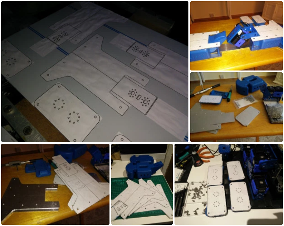
I was initially thinking of finding an online service to cut out the aluminium chassis parts, but then decided it would be faster and cheaper to just get some sheets 1.5 mm thick aluminium sheets from eBay and cut them on a jigsaw table. I used Fusion 360’s drawing tool to export to PDF the parts I needed to cut out: four chassis plates and four foot plates. I then printed them in actual scale and glued them on the aluminium to uses as traces.
Assembly
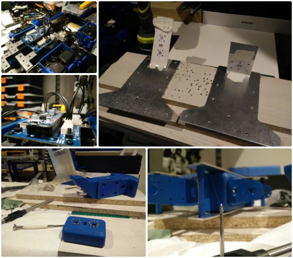
I threaded the holes on all the 3D parts, which were either 3 mm wide where the aluminium plates attach, or 2 mm at the leg and spine bracket attachment points. Using a tap for the 3 mm holes worked pretty well, but the 2 mm holes were more prone to being stripped or too loose, so manually threading the holes with the bolts worked better. Another issue was the infill surrounding the internal thread cylinder sometimes being a bit too thin. In retrospect, I’d try designing the 3D parts to use heat-set or expandable inserts, especially for the smaller threads.
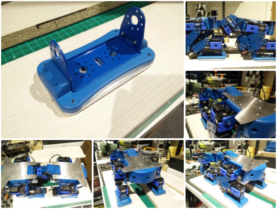
The servo brackets attaching to the chassis have a large number of holes (16 for each leg and one of the spine brackets, and 12 for the other spine bracket) so the screws so far seem to secure the brackets well enough. The spine section is under a lot of stress from the wight of the whole chassis and legs, so it will not be able to withstand much twisting force, and the servos may not be strong enough at this area, but I will have to test this in practice with new walking gaits.
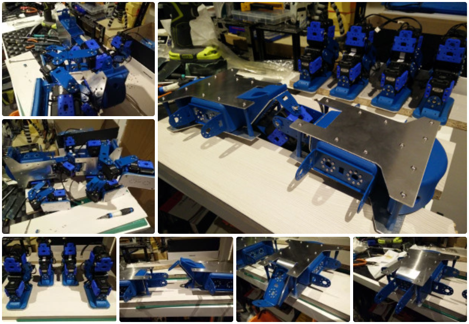
Conclusions
The custom chassis has finally made it from a 3D design to a reality, with relative success so far. Some of the threaded holes on the 3D parts are not as strong as I’d like, the AX-12 may be under-powered for the spine connection, and the brackets anchoring the spine may be the first to give way due to twisting forces. Also the chassis as a whole would benefit form weight-saving exercise and perhaps being thinned down. But this has only been the first iteration of the main chassis, and the robot design has now become a reality and seems to stand up well.
Discussions
Become a Hackaday.io Member
Create an account to leave a comment. Already have an account? Log In.