J.C. Nelson
-
The importance of choosing the right libraries
04/26/2019 at 05:34 • 0 commentsWhile I'm glad I spent some time looking at the pulses under an oscilloscope, what I found was that the minimum stepper pulse was working. How did I do this? Well, my DSO scope has only a 10us option for its finest sampling setting, so instead I increased the minimum pulse to 30us...and was able to measure it just fine. Pulse count, as well, was right down the line.
But I began considering something different, something I should have considered earlier.
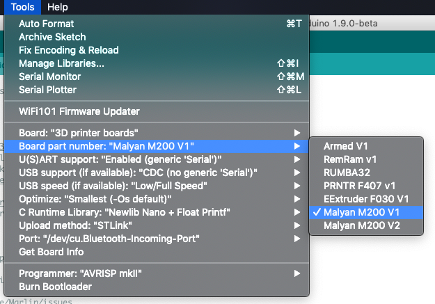
The display controller communicates movement using float numbers for the GCODE injected. Arduino has the option to have very small runtime libraries, without the ability to print floats or parse them. The homing moves (G28) inject distances directly. After looking for a bit, I realized I hadn't selected a runtime with float support, so I went back and adjusted my settings--and it moved.
![]()
-
Oscilloscope, Ahoy
04/24/2019 at 16:38 • 0 commentsThe USB init Pull Request for Malyan M200 V1 systems is now officially merged into ST's Arduino core, which means USB works reliably now. A few minor changes to define UWMEM addresses and allow the MalyanM200 pins to be used with the ST core, and I can compile using the Arduino IDE every time, reliably.
That's great.Heaters work, USB, the LCD, fans, SD card, etc. All of that works just fine. There's just one little problem:
THe motors don't move correctly.
Now, if you go back through the project logs, you'll see this is a recurring problem I've fought with a number of different reasons. Sometimes it's the min pulse length (needs to be 2 on my Malyan boards, even though the documentation claims 1 is sufficient). Sometimes it's the ISR timer prescalar/frequency. Some advice from the Marlin github issues suggested that it would be a max rate issue, so I adjusted the settings to match the M200's defaults.
No luck.
Homing moves successfully raise the Z axis, but the other axises don't even budge, they'll occasionally stutter.
And I can't lower the Z axis.
Now, the Z axis is unique in that its step count is ~3x the number of any of the others. This means that missing pulses or incorrect ones have a margin of error. To figure this out, I needed to measure the pulse lenghts and see what's being sent. I do own a scope, a DSO138 hobby scope that I 3d printed a case for. It's a single channel, but I only need to measure one, so I hooked it up to the stepper output after checking to make sure the scope could handle it and ran some tests.
The stepper output is garbage.
But it turns out I made a critical mistake. I'm not measuring the actual pulse, I'm getting the output from the stepper driver. I have two approaches I'm going to chase in parallel. First off, on V2 hardware, there's a beautiful JP socket for Serial2 (what I used to hook up the BL-touch). I'm going to cheat and define the TX and RX pins as X and Y step. I can measure those directly.
Secondly, there's a board definition in Marlin (STM32F1_R) which isn't for a real printer, it's a bluepill. I'm going to get that compiling and load it onto a bluepill. That will let me measure the pulses directly.
It could be that I have everything configured wrong in the timer. It could be that the no interrupts code is causing some blocking. We'll find out.
-
USB Revisited, plus Timer work
04/16/2019 at 17:12 • 0 commentsI've been fighting PlatformIO to get it to build, so for now, I switched back to compiling with the Arduino IDE. I wasn't terribly surprised to see that the V2 board (an STM32F070 board) simply worked with USB CDC. Why? Because the V2 doesn't have a pullup transistor. It has the place for one (and I'm near certain PB9 could be used as an output with a little soldering), but it doesn't have it.
The V1 board variant turns on PB9 on variant init.
However, V1 USB doesn't work. The reason why is related to a previous log on USB support. The ST Arduino core signals reenumeration by pulling DP low. However, if DP is being fed by a pullup transistor, pulling it low alone doesn't do the trick.
To fix this, we need to make the reenumerate function weak, something I've opened a PR to do, and add a reenumerate to our variant, something I've also done.
Timer wise, we have to deal with the fallout of an earlier log where I noted that timer conflicts with hardware PWM could cause resets. To handle this, I consulted the timer map and the PWM map.
We use PB3, PB6, PB7, and PB8 in analog write (FAN2, HEATER, HOTEND, and FAN1). This leaves timers 1 and 3 open, which just so happen to also (apparently) be available on the 070. So I've updated the pin map and will test.
-
Board Support is In
01/30/2019 at 06:24 • 4 commentsA small log to note that the current master branch for ST's arduino core now supports Malyan's M200 V1 and V2 (and possibly delta/M100). I am extremely limited in hacking time at the moment, but it's in.
Go forth, build Marlin, and enjoy.
-
V2/STM32F070 Support
11/23/2018 at 21:37 • 1 commentHaving successfully gotten a mostly functional firmware on the V1/STM32F103 MCU Mini, I moved on to supporting the STM32F070 processor. That's the one that drives the Monoprice Mini Delta, the later run Malyan M200V2, the Malyan M300/Monoprice Mini Pro (aka V3), and highly likely to be the same chip in the new CR-10 clones from Malyan.
I do not know about the SLA printers - if anyone owns one, I'd love to know fi the motion controller is a variant wired to galvos or not.
In enabling V2 support, I discovered some ugly hacks I'd done to to the build flags and unwound them, and in a few hours, had a working firmware that boots on V2 boards.
These are, as of yet, untested in printers.
Why? USB support. I'm waiting for the 1.5 release with its CDC virtual com port emulation, which allows you to hook the printer up via USB.
Regardless, it's time to begin the work of integrating the boards for a proper PR, and also, figuring out how to support the Malyan M100, which is theoretically a variant, but I have reports that the same firmware doesn't function there.
One note about V2 support:
Copying over the vector tables in STM32F070 variant init means that pre-main intializers which use interrupts are in trouble. The vectors aren't in place until variant Init, which is part of the main() function (for arduino folks, that's before setup()).
I don't know yet what I"m going to do (if anything) about this.
-
Core Woes Unwound
11/22/2018 at 16:04 • 0 commentsAs noted in the last log, I'd seen some on-again, off-again woes in the ST official core for Arduino. I thought they'd been transient, the result of the mismatch of cores and core-specific hacks in Marlin's code, there's a general rule I should have remembered:
If you don't know how you fixed it or why it was broken, it isn't fixed, only hiding.
And sure enough, a few rebuilds later, the behavior manifested again, as though I wasn't feeding the watchdog.
So I did what any good programmer would do, and put watchdog statements in my code and looked for them. Look, I'm feeding the watchdog.
I tested running the temperature ISRs directly from the main() loop.
Then, I stumbled on a key. The behavior only manifested once Marlin had sampled the temperatures enough to average them.
This behavior manifested on a bluepill as well as the M200 mainboard, so I stuck with the bluepill, using gdb to debug, and there I began to unravel a call that made no sense. No matter how often I broke in, the core seemed to be answering an interrupt for timer 4.
No problem, that's the stepper timer, and it runs quite often.
But with GDB, I noted that nothing was getting dispatched, as if my ISR had gotten lost. I stepped back and put a breakpoint on timer initialization, hit the reset button.
Both my ISRs got registered as expected. Perhaps some sort of memory corruption?
But on a whim, I left it running, and a moment later, I hit an unexpected init.
It turns out that ST's official core uses hardware PWM for EVERYTHING. STM32GENERIC uses a single timer for all pwmWrite (analogWrite) calls. Maple uses a mix of hardware and software PWM.
And in ST's official datasheet, the different pins the mini uses for fans and heaters (the two PWM entities) are mapped to timers 2 and 4.
Bingo.
For now, the answer is to shift timers to 1 and 3. 1's the right value for the stepper timer, because it holds a larger (32 bit) value, which is important when we want to run very slowly.
Long term, I'll either need to request (or write and generate a PR) a simpler PWM implementation which doesn't consume every timer on the board.
But with that change, my M200 mainboard remains running. I can print using the LCD...sort of.
We need USB support (coming in 1.5 of ST's official core) before this can be usable by the world, but we're getting there.
-
More Core Weirdness
11/13/2018 at 15:15 • 0 commentsAfter a ton of debugging where nothing made sense, I moved away from using the M200 mainboard and started debugging on a bluepill using...another bluepill. Yes, you can convert a bluepill to a blackmagic probe, and getting that set up was actually key to another project of mine, hacking the obfuscation in Lerdge boards via the PC/SP registers (in essence, while Lerdge has protection set, you can't stop reading the SP/PC registers, so a firmware with the PC counter hacked and SP set to a known value will yield 4 decrypted byte values at a time.
This gave me the chance to take a breath and step away, and when I came back, I synced up, and lo and behold, the mysterious crashes went away. While I can't use the malyan LCD and the serial definition at the same time, it's now at the point where I need to plug a main board into the printer and begin actually testing...
-
Minor Note - Uploading to SD Card via Arduino IDE
10/22/2018 at 16:23 • 0 commentsI'm still using PlatformIO as my editor for now (aka Atom, not VSCode yet). The M200 doesn't support ST-LINK upload or serial, and in fact, I want to use IAP so that users can move off of the Marlin 2.x build with no problems.
So that left me copying the binaries to the SD card by hand...until I decided to do better.
To do this, I added a copy to SD card method for uploading, set it as my board uploader.
In boards.txt:
# Upload menu
MALYANM200.menu.upload_method.CopyToSD=Copy To SD
MALYANM200.menu.upload_method.CopyToSD.upload.protocol=
MALYANM200.menu.upload_method.CopyToSD.upload.tool=copyToSD
In Platform.txt:
# Copy To SD for M200
tools.copyToSD.cmd.windows=copy
tools.copyToSD.cmd.macosx=cp
tools.copyToSD.upload.params.verbose=-batch
tools.copyToSD.upload.params.quiet=--batch-silent
tools.copyToSD.upload.pattern="{cmd}" "{build.path}/{build.project_name}.bin" /volumes/PRINTER/update.bin
This is in no way perfect. I'd like to call a script so I can output a "finished." It would also make sense to let the path be selectable and unmount the drive afterwards since I'm on OSX.
However, in terms of quality of life? This has been so very helpful. I insert my SD card adapter + SD card, choose upload, eject, and it's running.
I'll explore how to change this to call a script soon so it can echo that it's done (as well as figure out how to dismount a volume by name) but there you go. "custom" upload tool.
-
ST Core Progress
10/22/2018 at 16:16 • 0 commentsAs I noted last time, I had an official build up and running (and crashing) with the ST Core. The first thing I did was a huge set of hacks. Remember, at this stage, I simply want to get something working. The next stage will be to tease out the proper fixes for each of my hacks. That said, I knew the first thing necessary, and did it -
Adding support for an already running Watchdog to the IWatchdog library. The M200 uses the IWDG, not the WWDG. The W in WWDG stands for "Window" (as opposed to "Independent" for IWDG) and means you need to reset the watchdog within a specific window or else suffer the consequences.
I hacked together an "alreadyRunning()" call for the IWDG and moved on. Now I could boot Marlin (no USB support) and see the output. How am I doing this? I have a TTL converter hooked to SERIAL1 - the display port. I disabled the Malyan LCD support and set Serial to Serial1, allowing Marlin to spew to my serial monitor.
It reset every eight seconds.
Now, this should set off alarm bells, since that's the reset period of the IWDG, but some testing showed that if I short-circuited the loops, my code ran just fine.
So this began a series of adding debug statements and watching the spew, and soon enough I came to the conclusion that this was an ISR issue.
Why? Because if I disabled all interrupts, the machine kept running, though serial, of course, didn't work so well.
So I commented out the temp interrupt, moving the watchdog reset to the inner loop.
Everything ran.
Enabled the stepper ISR-- boom, random crashes return.
So, where to from here?
Now we need to know if it's a macro/HAL issue, or if the stepper ISR itself is crashing. Fortunately for us, this is relatively easy to rundown. To do so, we'll put a return immediately after the stepper IRS's function begins. If it's an enable/disable/timing/macro issue, the machine will still reset. If it's something deep down, it won't.
Once I had an M200 I'd soldered debug headers to, then reset the protection bit, flashed the bootloader back onto, and could debug via ST-link. We may wind up back there.
But not yet.
![]()
For those of you wondering when V2/070 support will come, fear not. Once this is running, adding a board definition for 070 becomes relatively simple, porting the board definition/startup code from STM32GENERIC. That will likely be AFTER USB support. We need to have something functional before we extend scope.
-
A Question of Cores
10/18/2018 at 19:15 • 0 commentsAt this point it might look like we're done, but the truth is...not really. Why? Because V2 and MP Mini Pro both require STM32070 support.
As noted in previous logs, I implemented a working HAL based on the STM32GENERIC core, but that core is pretty much in hibernation. Turns out, there's a new core in town, ST's Official Arduino Core. It's slowly progressing, as it's something ST wants to work right.
Moving to this core meant switching to the Arduino IDE to build, and I spent a few days just getting everything configured such that I could use a symlinked GIT repo as the core. Once I did, I dove in, using my work from STM32GENERIC as a guideline.
First blocker: Custom startup files. STM32GENERIC and the ST official core both #include common startup assembly. This is a good approach given how many different variants of ST"s MCUs there are.
But for the M200 series boards (and their M100 cousins) this is a no-go. As noted previously, the bootloader doesn't set SP and there's an interrupt/systick watcher running which crashes the printer if certain values are overwriten.
So I asked for help, and the core maintainer added the ability to specify a custom startup file. A few hours of hacking later, I had a minimal M200 build running (and crashing).
Problems:
1. VECT_TAB_OFFSET wasn't defined (again). Had to add it to the boards.txt.
2. Serial support is really, really strange in this core. I'm still wrapping my head around what Serial links to versus Serial1. In the end the working solution was "Serial with generic Serial" and output to Serial1.
3. USB....
In fact, let's drill into USB support. As I noted, the ST core is moving carefully, and CDC support is still under development. That current code doesn't work on 103 devices where timers are in short supply, but I hacked together a direct send/receive implementation, and encountered the next problem:
4. No USB Init. M200V1s require a pullup transistor to be enabled. This is under investigation.
5. Late Watchdog doesn't work. If the bootloader is already running, the IWatchdog fails to initialize and no longer feeds the watchdog correctly.
The first two are fixed for some version of fixed. 3 is undergoing a great deal of study, and 4 is the subject of some investigation. For now I'll likely simply turn the transistor on during System Clock config.
The watchdog will be the subject of my next work. For now I can load a build onto my V1 printer with no USB support and it runs for ~8 seconds before reseting. I believe the fix for this is to have a flag that says "The watchdog is already running" in the library.
We'll see.
Monoprice Mini Marlin 2.0 Support
Getting Marlin to run on the Monoprice Mini/Malyan M200.