 matt
mattThe most complicated part was creating a mount that fit my glasses. I started out by taking pictures from the front and top, converting it to a black and white image, and exporting to a BMP. Next I used Numpy to import the BMPs and convert them into an OpenScad-compatible polygon array. I used the polygons as a virtual "mold" to cut out a shaped from a block and then attached mounts to fit the arms of my glasses. After that it was a matter of building shapes to fit the battery, shutters, arduino and boost converter and fitting them on. This took a few iterations to get the fit right, but luckily 3D printers rock.
While the printer was doing its thing I put the software together. This was really simple as the gesture sensor has an Arduino library all ready to go. The "Gesture Sensor For Lunch Money" (listed in the links) was the inspiration for this project and made things really easy.
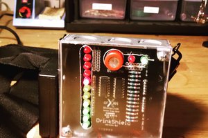
There's not much to the wiring either. The gesture sensor interface is I2C plus one interrupt line, and the shutters can be enabled simply by using 2 pins as current sinks.
I made a mistake with the Arduino, though. I thought it was a 3.3v board and that I could power it direction from the battery, but it's 5v so I had to add the boost converter. Luckily I had a handy place to put it and it fits fine.


 Miguel Barajas
 Rasank Patro
Good suggestion. Thanks.