 david
davidSure, you can buy after-market lighting kits. What fun is that?!? … especially for us Arduino-heads :-) If you aren't an Arduino-head, I could be persuaded to put together a kit.. Of course you'll still will be able to program it any way you want.
On the surface this is a pretty simple project. It reads 3 on/off switches and drives 2 LED strips. That’s all there is to it. However, this isn’t your typical stand-alone Arduino project. There are some subtle nuances of integrating it into an existing electrical system. Also, Pixel animation can be ... tedious, but hopefully my encapsulation can shield you from that.
Here are the skills and the items you will need to build this project.
- A willingness to dig into your bike’s electrical system. You’ll need to find and tap into:
- Switched 12V line
- Left turn signal line
- Right turn signal line
- Brake light line
- If you remove existing turn signals you’ll probably end up with a "hyper-flash" situation. This is a typical symptom when you replace turn signals with something that draws little amps like an LED. The best solution is to replace the turn signal relay. Alternately you can add load resisters to simulate the load of a normal incandescent bulb. I did the load resisters before I found out the turn signal relay is a better solution.
- Three 12V relays (I chose the small reed type relays)
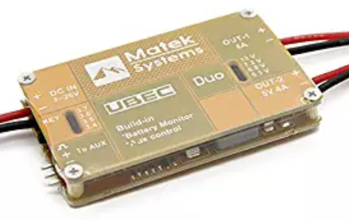
- 5v power supply capable of a continuous 5 amps (not the peak rating)
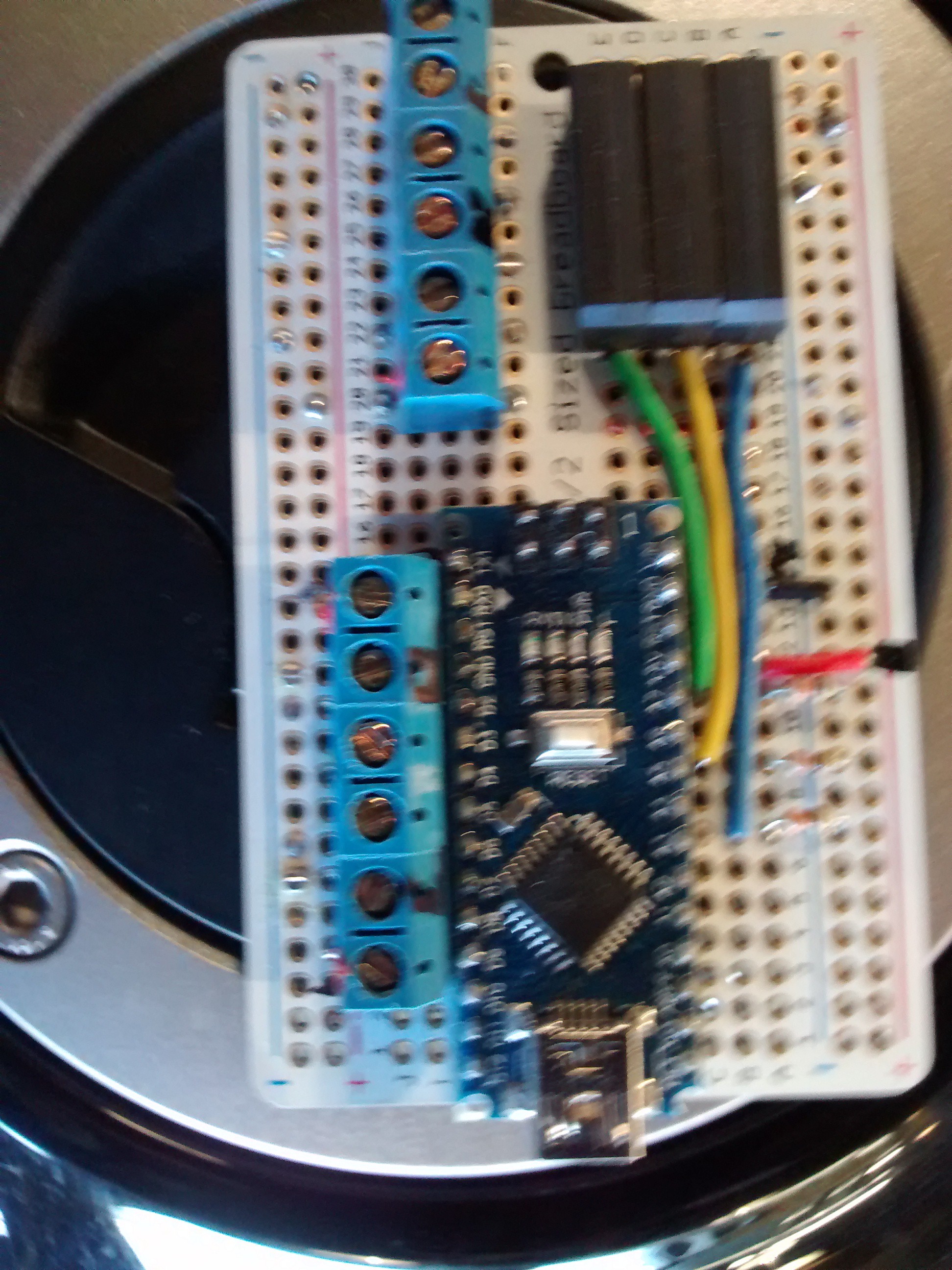
- An Arduino of some flavor. I used an Arduino Nano clone.
- Two - 5x8 WS2812 LED matrix (or matrix of your choice)
- Perf board
- Terminal blocks for connecting all the wires
- Wire
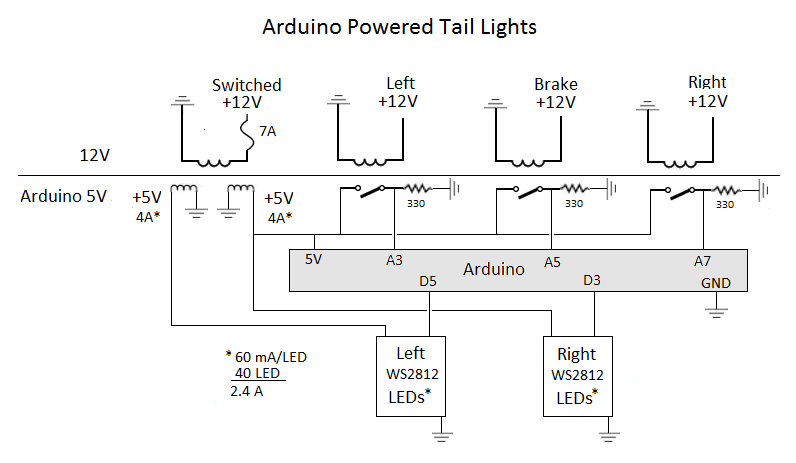
Notes on the schematic
- The goal of this project was to isolate the Arduino completely from the bike's electrical system. That is why relays are used to trigger the Arduino pins. You could probably use a voltage divider and avoid the relay.
- If you have a newer bike with LED turn signals, check the voltage going to your lights. It may already be 5V that could be fed directly to an Arduino pin.
- You’ll probably find it odd that I’m using analog to read the brake/turn signals. This was only done to simplify soldering of the prototype board so I didn’t have all the connections on one side of the Arduino Nano. Typically, you’d use digital pins for this.
- The switched 12V input line is on an existing 10A circuit on my bike. I fused the project at 7A so that if something goes wrong, hopefully it won’t take out my existing brakes and turn signals.
- Don’t under power the project! Each LED matrix could draw 2.5 Amps! As shown, I have a dual output power supply that is capable of 4A on each output and this works flawlessly! Two 3-amp BEC circuits would probably also work. If your Arduino LED flickers while the turn signals run, get a dedicated power supply for the Arduino, or power the Arduino with 12V to the VIN pin. My power supply shown below is good enough that I can power everything w/o seeing the Arduino LED flicker at all.
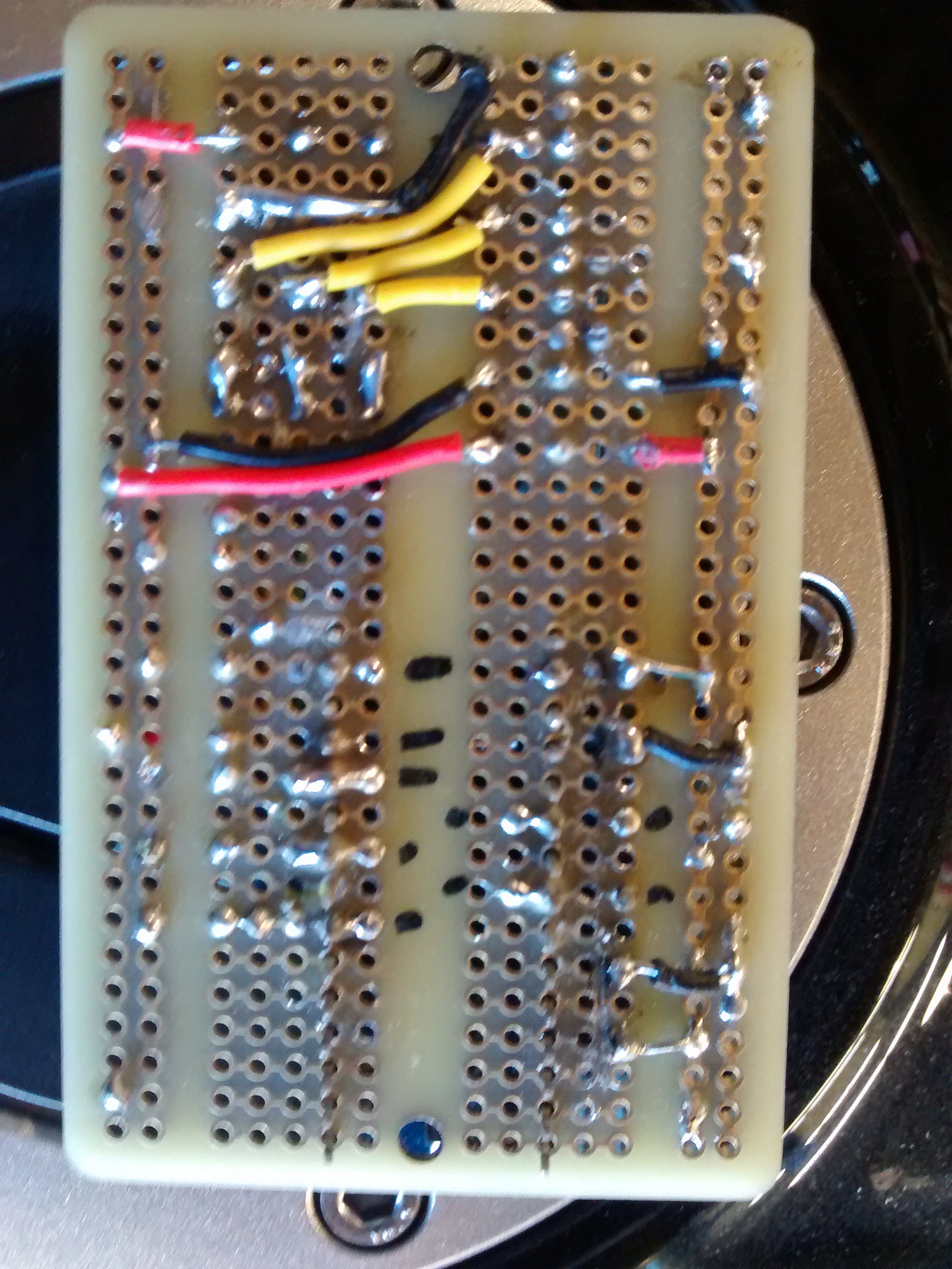
Building the circuit board
- I used an Adafruit perma breadboard (essentially a perfboard with breadboard traces). I hoped that the built-in traces would make a cleaner build. It’s not a perfect solution and some traces need to be scraped off. I’m ok with this idea, but not wow’ed so I haven’t included the layout. You can probably do a better job anyway.
- Things I might do differently:
- Take the time and design a PCB board
- Put in headers so the Nano can be replaced, but this will also increase the thickness of the build
- I’d like to try a TI MSP430 instead of Arduino
Building a test fixture
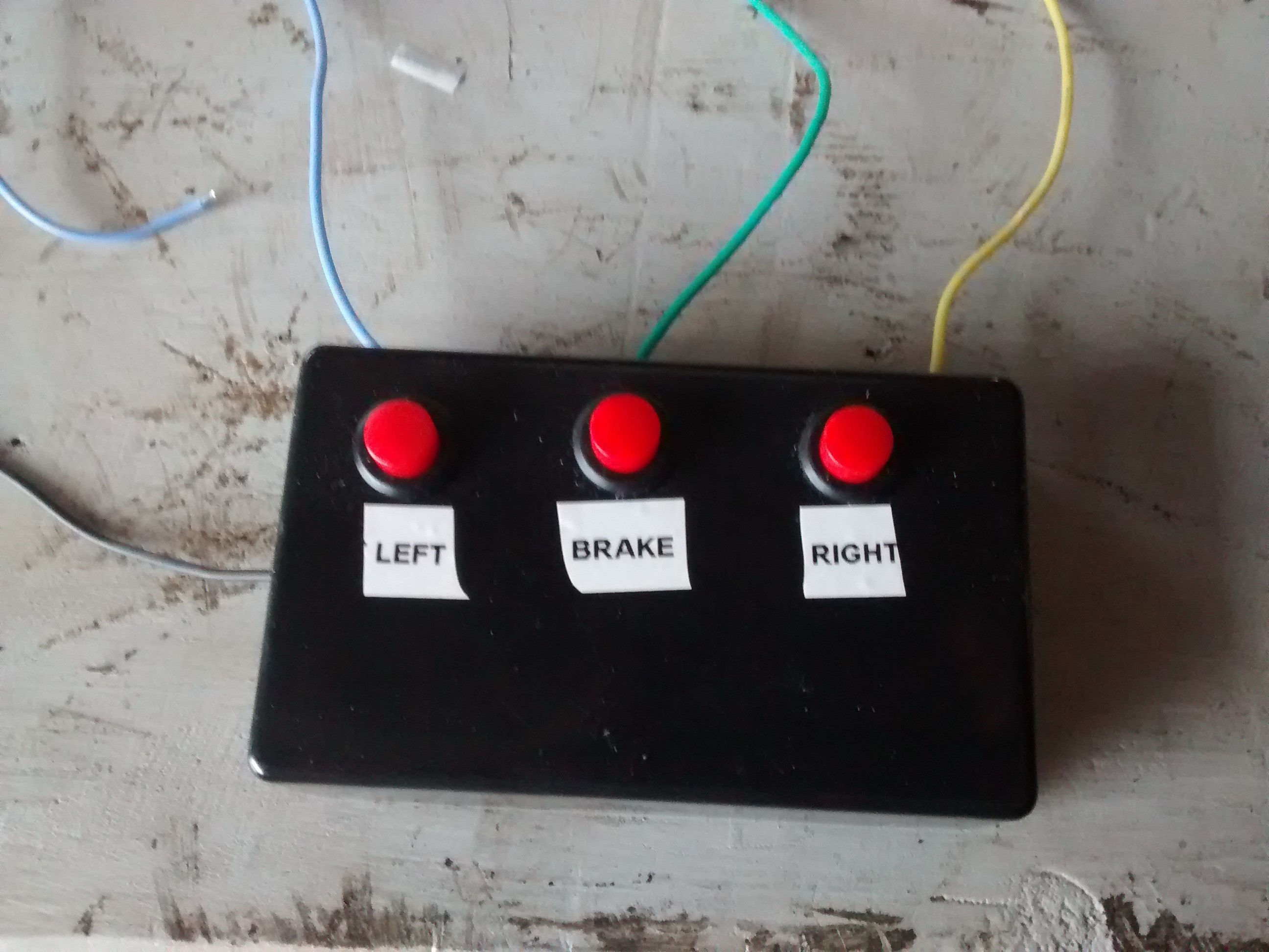
If you are modifying the code, you are going to want to build a test fixture so that you can develop and test at your desk rather than working on this out in the garage attached to your bike. I built a 3 button project box that feeds 9v to each of the three relays (I lucked out that 9v can trigger the 12V relays). The three buttons represent: left, right, and brake signals and you can test all combinations.
Arduino Projects
I learned early on in my Arduino adventures that it’s best to encapsulate LED animations in class libraries. That makes the animation reusable and cleans up your main Arduino sketch from all gory details allowing you to focus on what you want to do, not how to do it. Compiling this Arduino sketch requires 4 downloads:
- Adafruit neopixel library
- BlinkLed (my library that performs a simple blink animation. Used for brake and running lights)
- CascadeLed (my library that systematically illuminates a series of LEDs. Used for turn signal animation.)
- TailLight (Arduino sketch)
The method to my madness is to create instances of the LED animation classes specifying the LEDs to light, and the frequency. Then you simply call the instance on each control loop and tell the instance if it should be on or off. The instance keeps track of its blinking frequency and decides what to do. With the animation fully encapsulated like this, there are only a handful of lines of code in the sketch itself (excluding the instantiation code).
BlinkLed class library
Look in the header file of the class library for the details of the call sequence. You can also find examples in the sketch for instantiating and calling it for the brake lights and running lights. Basically, you pass in an array of pixels to light and the frequency.
example:
byte maxstop = 25;
byte StopPix[MAXSINGLEROW] = {
3, 4, 5, 6, 7,
11, 12, 13, 14, 15,
19, 20, 21, 22, 23,
27, 28, 29, 30, 31,
35, 36, 37, 38, 39
};
BlinkLed LStopLed = BlinkLed(&lstrip, &StopPix, maxstop, R, G, B, 19);
BlinkLed RStopLed = BlinkLed(&rstrip, &StopPix, maxstop, R, G, B, 19);
CascadeLed class library
Look in the header file of the class library for the details of the call sequence. You can also find examples in the sketch for instantiating and calling the turn signal signals. Basically, you pass in a two dimensional array of pixels to light and the frequency. The class will then cycle through the rows of pixels and light them in that order.
WARNING: For simplicity I have chosen to create constants to define the array sizes. This burns some memory for the sake of ease of use. If you choose to drive more than 40 pixels per bank, you may need to alter the constants defined in: CascadeLed\ArrayConstants.h.
example:
const byte maxrow = 5;
const byte maxcol = 8;
byte Rightpix[MAXROW][MAXCOL] = {
{ 0, 1, 2, 3, 4, 5, 6, 7},
{ 8, 9, 10, 11, 12, 13, 14, 15},
{16, 17, 18, 19, 20, 21, 22, 23},
{24, 25, 26, 27, 28, 29, 30, 31},
{32, 33, 34, 35, 36, 37, 38, 39}
};
CascadeLed RightLed = CascadeLed(&rstrip, &Rightpix, maxrow, maxcol, RT, GT, BT, 80, 900);
TailLight.ino Arduino Sketch
Not much to say here. The control loop is REALLY simple:
void loop() {
byte leftpin = (analogRead(LEFTPIN) > 50);
byte brakepin = (analogRead(BRAKEPIN) > 50);
byte rightpin = (analogRead(RIGHTPIN) > 50);
// animate or clear the turn signals
// PsudoOn is true when pin is high or between turn signal blinks (pin is actually low)
bool lPsudoOn = LeftLed.Blink(leftpin);
bool rPsudoOn = RightLed.Blink(rightpin);
// animate or clear the brake lights
LStopLed.Blink(brakepin);
RStopLed.Blink(brakepin);
// only turn on running lights. Let the overlays turn it off
// Clear will interfere with overlapping lights
if (!lPsudoOn && !brakepin) LRunLed.Set(true);
if (!rPsudoOn && !brakepin) RRunLed.Set(true);
}
Side notes:
Turn signals switch on and off and will disrupt the pixel animation because the blinking is faster than one animation sequence. The CascadeLed class has a timeout value to absorb the “off” part of the blink and pretend that the signal is still on. This pseudo on is passed back to the main control loop so it knows if the turn signal should be considered on or off instead of using the current pin value. The only minor consequence is that the turn signals don’t immediately turn off when the turn signal is turned off.
The pixel assignment between turn/brake/running lights overlap. That means turning off one LED animation may turn off the LEDs of another animation. This is only temporary until the current animation is on long enough to repaint its corrupted pixels. I’ve only seen this problem between the turn signal and running light animations. If you choose another running light pixel assignment, this may cause you problems. I’ll consider fixing it if it becomes an annoyance for someone else. For me I’m happy with current way it works.