Close
0%
0%

FL2k Experiments

Exploring the FL2k USB-to-VGA dongle for signal generation

Similar projects worth following
Since reading about Steve Markgraf's discovery that you can use cheap FL2000-based USB-to-VGA converters as general purpose fast DACs, I've become very interested in what I might do with them. This project chronicles my experiments.

This project is going to happen in the build logs: I'm basically treating this as a blog for ongoing experiments with the FL2k dongles.  This is a spin-off from #AM Band Voice Frequency Marker where I initially used this device to implement a project that had stalled for about a year.

For background information and the code you need to operate these dongles as general-purpose DACs, see the osmocom.org wiki page.  The short story is that there's a way to turn off the horizontal and vertical blanking interval on these inexpensive USB3.0 adapters so they can blast out 8-bit analog values at 100 MSPS or more on three channels.

Feedback or suggestions on these ideas are welcomed, as are collaborators.

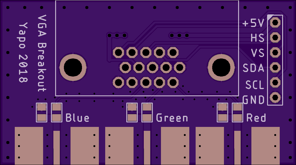
For anyone wishing to start experimenting with these dongles, I've designed a breakout board that brings the red, green, and blue channels out to SMA jacks and matches the 75-ohm output of the VGA to 50-ohms.  You can order the PCB from OSH Park.

So far, I've decided I want to explore the following things:

ZOH Limitations

Overcoming the zero-order-hold (ZOH) limitations on higher-order Nyquist zones.  The DACs in the FL2k don't have any explicit filtering, which is ideal for VGA output, and also allows you to generate RF outputs at higher frequencies than would otherwise be implied by the ~100 MSPS data rate.  But, there's an implicit "filter" in the DACs themselves: the zero-order-hold function, in other words, the fact that the DAC maintains a constant value during each sample time. This has the effect of filtering the higher-order Nyquist zones with a sinc-shaped envelope. In the plot below, you can see how the higher-order zones drop off precipitously up to 1.5 GHz.  The yellow curve is the envelope of the FL2k output, and the magenta the noise floor of the analyzer.  If you want to generate 1.5 GHz signals with this device, you are really fighting a lot of loss.
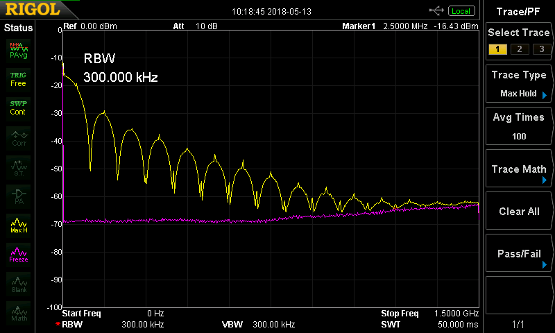
(Aside: to gather this envelope data, I generated a chirp signal from DC to 50 MHz, and output it at 100 MSPS.  I set the analyzer trace to "Max Hold," and let the envelope gradually fill-in while the chirp swept through the frequency range.)

Of course, you can change where the zeros are in this output by changing the sampling frequency, but the envelope is still limiting.  Ideally, instead of a zero-order-hold, the DAC would output infinitely narrow delta functions for each sample - this would produce un-attenuated harmonics for all Nyquist zones. Commercial direct-sampling RF DACs approach this ideal by shaping the DAC's impulse response. For example, Maxim's MAX5879 has four different selectable impulse responses (hint: read the linked page for much more info on the subject) that allow different envelopes to be created.   One of the responses is equal to the ZOH, a second returns the output to zero for half the sample period (more closely approximating a delta function), a third response inverts the DAC output half-way through the sample period, while a fourth combines the two, using true and inverted outputs for one quarter of the period each.  The article describes the resulting envelopes, which show less attenuation than the simple ZOH.

You can see the evidence of the ZOH in the time domain, too.  Here's a 10 MHz sine wave sampled at 100 MSPS through the FL2k:
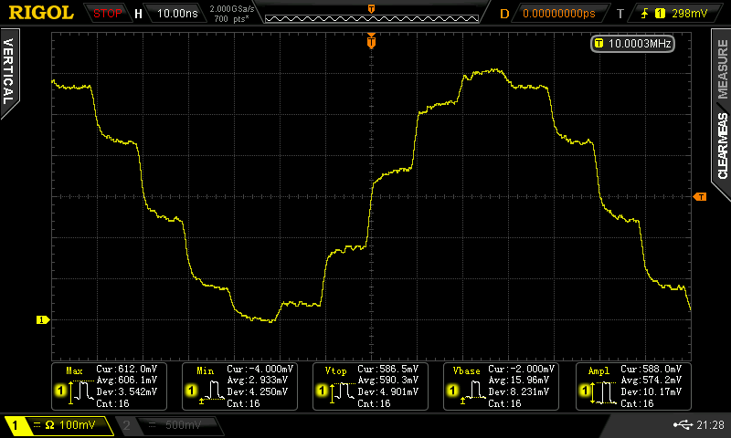
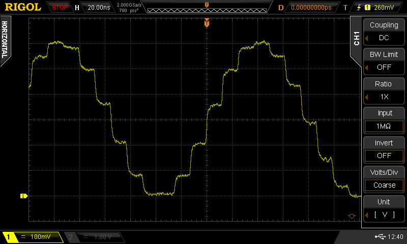
You can see the 10ns steps clearly.  The settling time for these large steps isn't great, but that could also be from a number of other factors, including the test setup.

How to improve this?  The idea would be to generate a fast sample of the DAC output.  For example, one could use a diode sampling gate, or maybe even just use a diode to shunt the output to ground for some (or most) of each sampling period.  To drive the sampler, you'd create a short pulse based on output from either the green or blue channel (see below...

Read more »

  • DAC Impulse Responses

    Ted Yapo05/15/2018 at 23:26 0 comments

    I wanted to copy these figures from the Maxim application note, but they're copyrighted and whatnot, so I wrote some quick python to calculate Fourier transforms for piecewise-constant functions and drew my own.  I would have paid good money for access to something like this when I took those undergrad courses...

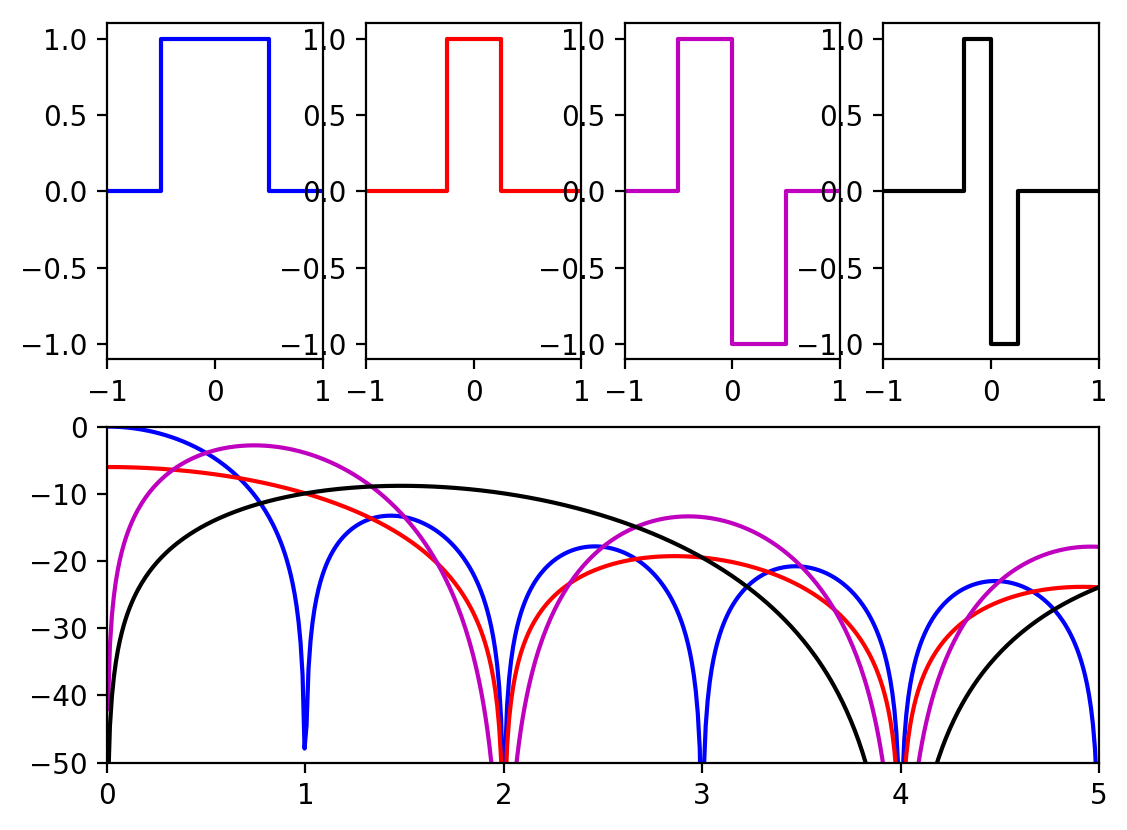
    Along the top are the four DAC impulse responses supported in the MAX5879, and in the bottom plot are the corresponding output envelopes in dB vs frequency (1 = the sampling frequency, so the first Nyquist zone extends from 0 to 0.5). 

    The first response (blue) is the familiar zero-order-hold, which just outputs a constant value during each sample period.  This is the response implemented in the FL2000 chip.  You can see that the output spectrum has zeros at multiples of the sampling frequency.

    The second response (red) drops back to zero (known as return-to-zero) for half the sample period.  This results in an output envelope that has zeros at even multiples of the sampling frequency.  This is beginning to approach the ideal of an infinitely narrow output sample, which would have a flat output spectrum.

    The third response (magenta) inverts the output for half the cycle.  This has a zero at DC, so is only useful for RF generation, not baseband signals, but has a higher envelope in certain Nyquist zones.

    The last response (black) also inverts but returns to zero for half the period.

    You can see how choosing one of these outputs from the DAC could really come in handy when using higher-order Nyquist zones: you can tailor the output envelope for the frequency you want to create.

    One of the goals of this project is to create a simple, cheap add-on to the FL2k dongles to modify this response and allow better generation of higher frequencies.

    Oh, I guess I'll drop the code that generates the figure here.  It's a one-off, so it ain't pretty, but it works:

    #!/usr/bin/env python
    
    import numpy as np
    import matplotlib.pyplot as plt
    
    
    t0 = np.array([-2, -1, -1, 1, 1, 2])*0.5
    h0 = np.array([ 0,  0,  1, 1, 0, 0])
    
    t1 = np.array([-4, -1, -1, 1, 1, 4])*0.25
    h1 = np.array([ 0,  0,  1, 1, 0, 0])
    
    t2 = np.array([-2, -1, -1, 0,  0,  1, 1, 2])*0.5
    h2 = np.array([ 0,  0,  1, 1, -1, -1, 0, 0])
    
    t3 = np.array([-4, -1, -1, 0,  0,  1, 1, 4])*0.25
    h3 = np.array([ 0,  0,  1, 1, -1, -1, 0, 0])
    
    fmax = 5
    n_points = 1000
    
    def plot_pair(t, h, style):
      f = np.linspace(-fmax, fmax, n_points)
      H = np.zeros(n_points, dtype=complex)
    
      # calculate Fourier transform H(f) for piecewise-constant function h(t)
      for i in range(1, len(t)):
        H -= h[i] * (np.exp(1j*2*np.pi*f*t[i])/(1j*2*np.pi*f) -
                     np.exp(1j*2*np.pi*f*t[i-1])/(1j*2*np.pi*f))
    
    
      plt.plot(t, h, style)
      plt.axis([-1, 1, -1.1, 1.1])
      plt.subplot(2, 1, 2)
      plt.plot(f, 20*np.log10(np.abs(H)), style)
      #plt.plot(f, np.square(np.abs(H)), style)
    
    plt.subplot(2, 4, 1)
    plot_pair(t0, h0, 'b')
    plt.subplot(2, 4, 2)
    plot_pair(t1, h1, 'r')
    plt.subplot(2, 4, 3)
    plot_pair(t2, h2, 'm')
    plt.subplot(2, 4, 4)
    plot_pair(t3, h3, 'k')
    plt.axis([0, 5, -50, 0])
    #plt.show()
    plt.savefig('DAC_impulse_response.png', bbox_inches='tight', dpi=200)
    

  • Interpolating with transmission line?

    Ted Yapo05/15/2018 at 04:33 4 comments

    So, I started playing around with transmission line models for generating short sampling pulses, and it occurred to me that you could use a transmission line to interpolate between DAC samples.  It's kind of like doubling the sample rate just using a piece of wire! Here's a circuit I've been playing with:

    The circuit is amazingly simple.  The voltage source and 50-ohm resistor model the FL2k DAC (with impedance-matching network to have 50-ohm output, like on the breakout PCB).  The only other element in the circuit is a 50-ohm transmission line cut to have a 2.5ns delay (the delay must be one quarter of the sample period).  This line is literally just a piece of coax open at one end. The circuit works by taking advantage of the signal reflection from the unterminated end of the transmission line.

    Here are the input and output waveforms from the simulation:

    The bottom (red) trace is the input.  I've simulated a 100 MSPS DAC generating a 10 MHz signal (that's the equation controlling the behavioral voltage source).  The top (green) trace is the output of the circuit, which shows that another sample point has been interpolated between each pair of input values, which could be mistaken for doubling the sample rate.

    How does it work?

    The unterminated end of the transmission line causes a reflection of each step in the input voltage from the DAC.  Since the reflection must travel the line both ways, it takes 5ns for the reflection of a DAC step to get back to the summing point where the output is taken.  This 5ns is half of the sample period, so the DAC by now is half way through the next sample.  Summed with the reflection of the previous sample, this creates an interpolated point which is the average of the two adjacent samples.

    Is it practical?

    I don't know yet.  It's too late tonight to get this up and running in hardware.  I'll have to try it as soon as I get a chance.  In simulation, anyway, it certainly looks interesting.

    Just to be clear, there aren't twice as many "real" samples being generated; the Nyquist rate for this system is still 50 MHz even though there are essentially 200 MSPS being output.

    At this time of night, I'm not even entirely sure what this achieves, but I can figure that out tomorrow.

    EDIT: I can't sleep.

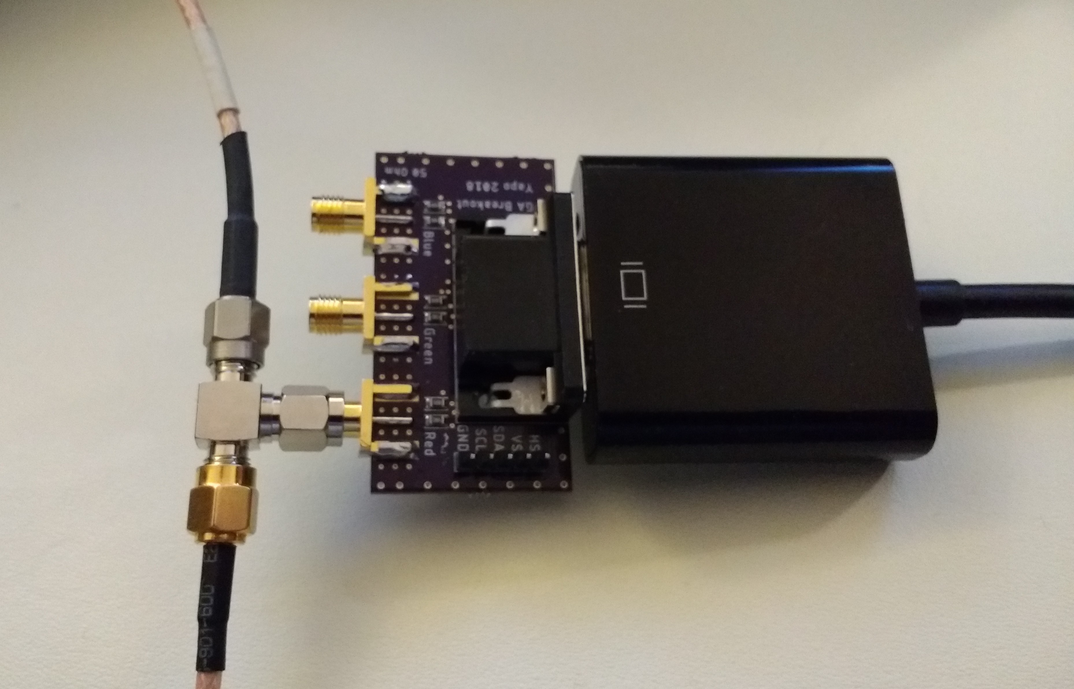
    I just had to try it out.  I used an SMA T-connector to add the unterminated line to the output of the FL2k dongle (the other line goes to the oscilloscope).

    To test it, I generated a 6.4 MHz signal using an 80 MHz sample rate (about the fastest I can do through my USB 3.0 hub).  With no line connected to the T, the output clearly shows the 12.5 ns sample periods:

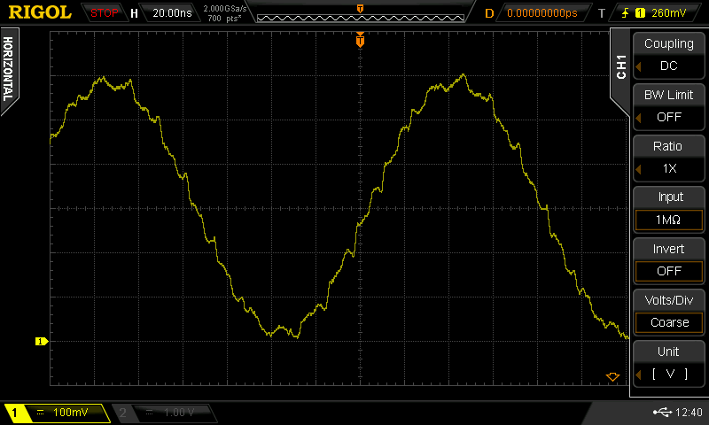
    After connecting a line of around the right length, you get this waveform:

    it certainly looks like it's doing something.  Hopefully this will be enough to allow me to sleep, and I can look with the spectrum analyzer tomorrow...

  • Updated Breakout PCB (again!)

    Ted Yapo05/15/2018 at 01:36 0 comments

    I modified the breakout PCB to include the +5V line, which I had overlooked before.  The FL2k dongles, at least the ones I have, do supply 5V on this line.  The latest design is in the GitHub repo, and the PCB is shared on OSH Park.

    I think this is the last iteration.  Probably :-)

View all 3 project logs

Enjoy this project?

Share

Discussions

Johny Radio wrote 10/12/2018 at 17:49 point

"It's kind of like doubling the sample rate"

- It looks like you're doubling the number of steps, ie increasing the resolution. i believe that's the equivalent of adding 1 bit of resolution. 

  Are you sure? yes | no

Ted Yapo wrote 10/12/2018 at 18:00 point

Yeah, it kind of looks like both of these things, but really, it's just a linear filter that can't do any magic :-)  It looks interesting when you tune the delay line to half the DAC sampler period, but it's still just a linear filter after all.

  Are you sure? yes | no

InverseInductor wrote 05/24/2018 at 22:45 point

For your high speed digital one shot, you might want to consider potato semiconductor. They make 74 series logic chips that can run at GHz rates. The PO74G86A and PO74G04A might be what you're looking for.

  Are you sure? yes | no

Ted Yapo wrote 05/25/2018 at 02:19 point

I've run across those datasheets several times, but I've never seen any of their parts.  It would be interesting to play with some.

The problem with the inverter-xor gate one-shot is that the pulse width is determined by the delay through the inverter, which is typically poorly specified (like a range of 2-3x over supply voltage ranges, and maybe only given as a maximum).  I think a piece of coax would make a better delay element.

But, yeah, those potatoes look cool :-)

  Are you sure? yes | no

K.C. Lee wrote 05/25/2018 at 08:35 point

Use a variable supply on it and now you have a variable delay for a ring counter.  Need some control loop to make a PLL or a Frequency Locked Loop as it isn't linear.  ~1GHz divide by 256 digital counter can be found in old cable converter tuners.

  Are you sure? yes | no

Nikola Stevanovic wrote 05/22/2018 at 11:29 point

Any thoughts on making this dongle be used as a FM transmitter, maybe with some extra hardware to be used as a real FM radio simulator ( with bandpass filter, switching different channels etc... ) ?

  Are you sure? yes | no

Ted Yapo wrote 05/25/2018 at 02:14 point

The osmo-fl2k software already supports wideband fm generation. See the example on the wiki page:

https://osmocom.org/projects/osmo-fl2k/wiki

  Are you sure? yes | no

Nikola Stevanovic wrote 05/25/2018 at 14:08 point

Wow i havent noticed this, thank you !

  Are you sure? yes | no

ArsenioDev wrote 05/14/2018 at 18:44 point

Dang, Ted continually has some of the coolest projects. 

  Are you sure? yes | no

Ted Yapo wrote 05/14/2018 at 20:15 point

Thanks!

The secret is never completing anything ;-)

  Are you sure? yes | no

ArsenioDev wrote 06/04/2018 at 20:12 point

Hahahahahahhahahahahhahahahahahahhahahahhahahah
>looks at backlog of 370 projects
I know what you mean lol

  Are you sure? yes | no

K.C. Lee wrote 06/04/2018 at 22:09 point

It is not easy to find something hard enough/interesting to challenge yourself, but at the same time not overestimating your ability/attention span.  I tend to fail the 2nd part a lot.

  Are you sure? yes | no

Ted Yapo wrote 06/05/2018 at 02:29 point

@K.C. Lee I'm trying to set the difficulty threshold so I can only complete half the projects I start.  I'm sure that's an optimum under some metric.

  Are you sure? yes | no

AVR wrote 05/14/2018 at 14:52 point

following!

  Are you sure? yes | no

Ted Yapo wrote 05/14/2018 at 15:51 point

I think that was the quickest like/follow I ever got :-)

Thanks!

  Are you sure? yes | no

Similar Projects

Does this project spark your interest?

Become a member to follow this project and never miss any updates