 Jay Francis
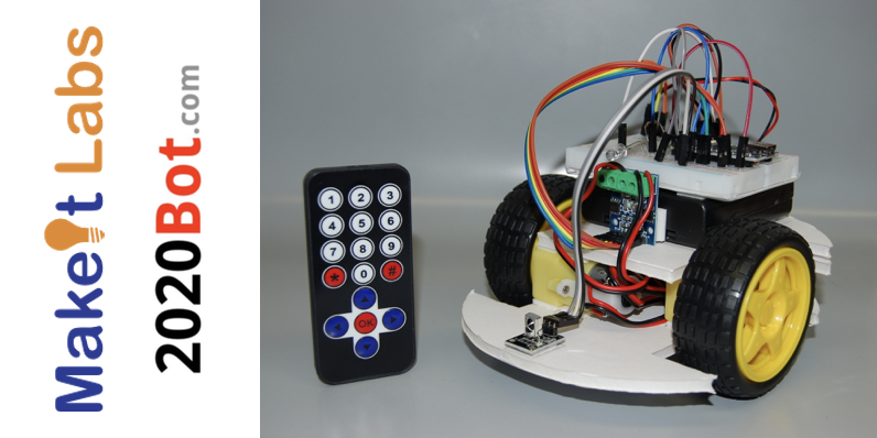
For Arduino Day 2018, MakeIt Labs held a Build a Bot class in the morning followed by an afternoon of robot hacking. The grand finale was a Robot Dance Party, complete with a disco ball, fog machine, strobes, lasers, and of course... Dancing Robots!
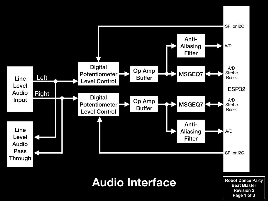
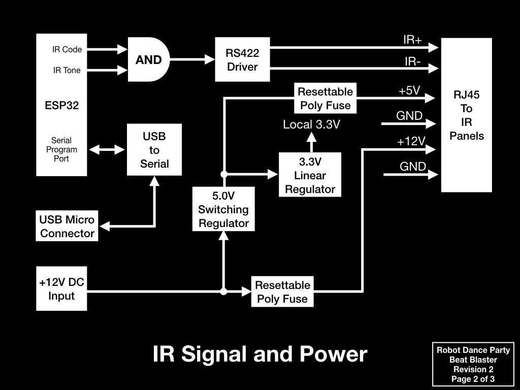
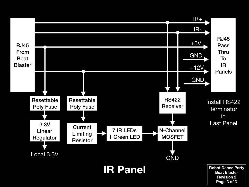
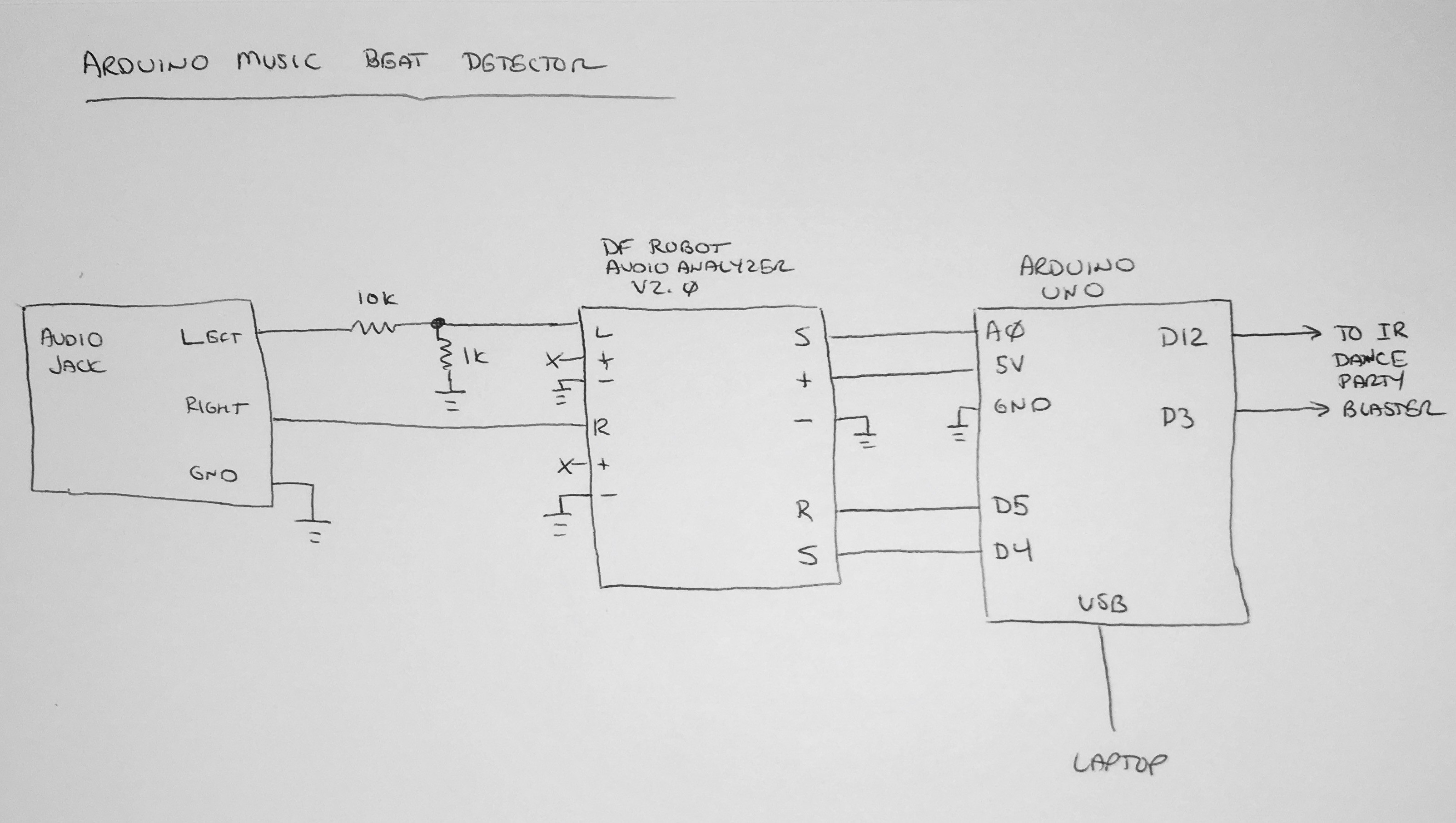
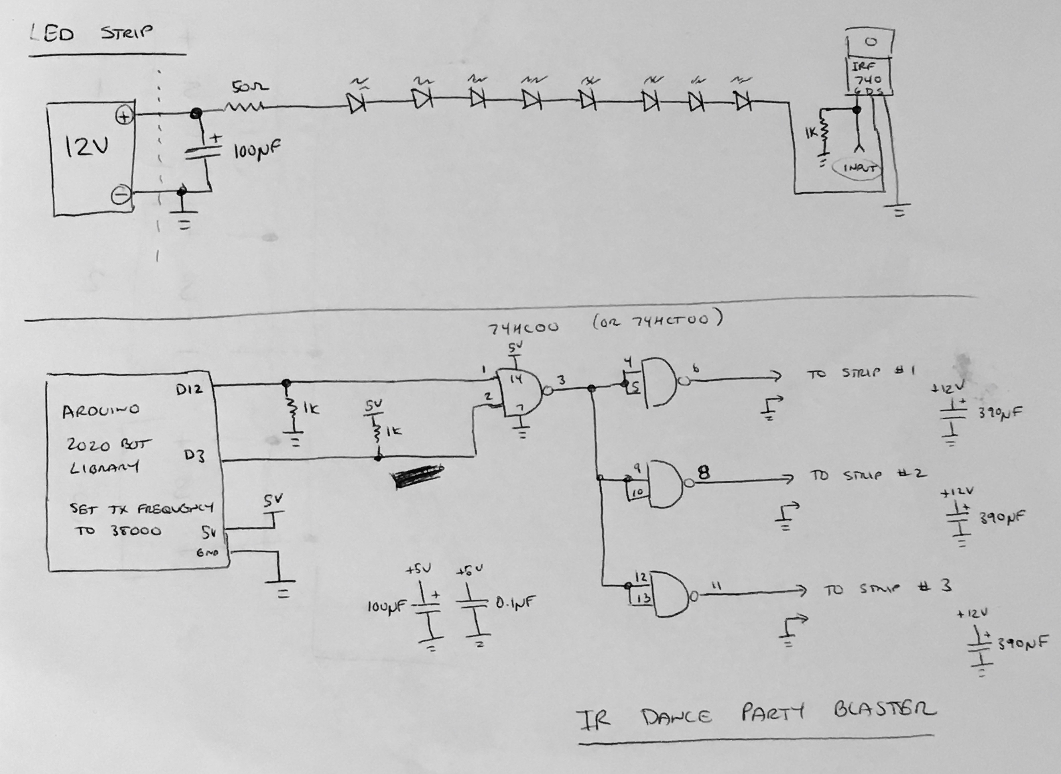
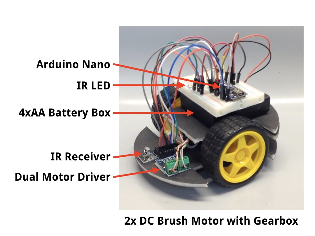
These little robots are no strangers to parties. Hackaday even caught one dancing on the table (and passing beer) at the 2017 BAMF meetup. Being simple creatures, they don't have a really good sense of rhythm. You can't blame them, they have no ears, but they do have an IR receiver. To help them get their groove on, we hacked together a music beat detector (Arduino Uno + MSGEQ7 Graphic Equalizer Chip + firmware) and blasted out IR codes synced to the beat. A little firmware magic on the robots and... Dancing Robots!
We're going to capture the current state of the project (so we actually have all the info in one place, and not on random napkins), fix the problems we ran into, and then make some improvements.
Since this happened to coincide with the Robotics Module Challenge of the 2018 Hackaday Prize, we're also going to distill the breadboard hacks and firmware into a simple beat detector module so others can host their own robot dance parties.
 deʃhipu
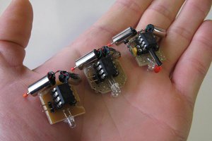
 shlonkin
 Rodolfo
 John Rampelt