 Jay Francis
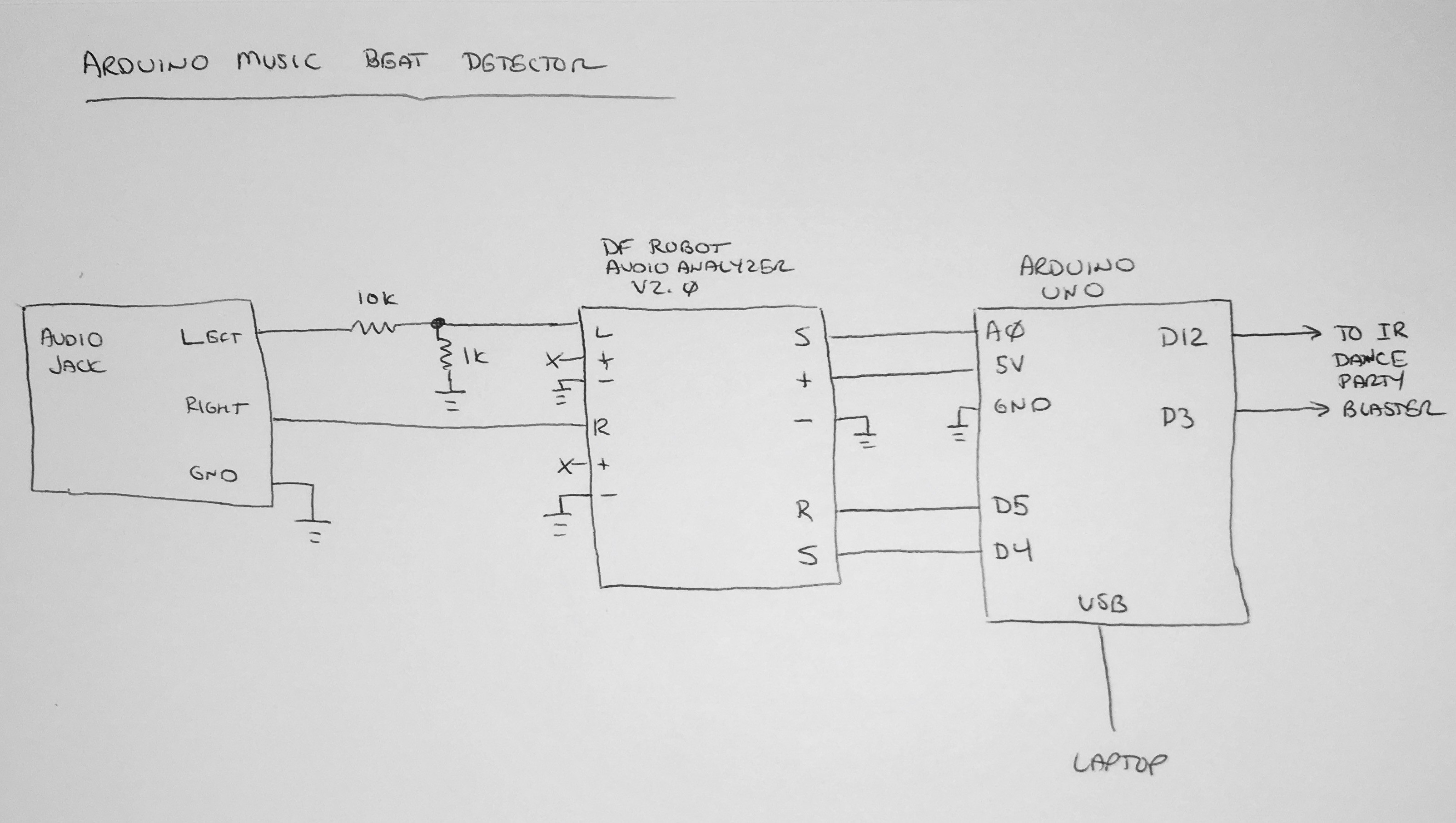
In true maker space spirit, we hacked the beat detector and IR blaster prototypes together over a couple of evenings. For the prototype, we used DF Robot's breakout board for the MSGEQ7 graphic equalizer chip.
This chip is pretty cool... it contains seven bandpass filters with peak detectors, and an analog mux. You send it a reset pulse, then a series of strobe pulses. With each strobe, the analog mux passes the output of one of the seven peak detectors.
Using an Arduino Uno, we hooked up two digital outputs for Reset and Strobe, and one analog input to read the values from the filters/peak detectors.
The idea is, with some firmware smarts, we should be able to look for the music's beat down in low bands (especially if we pick the right music!). This was enough for us to start, and yes, we could probably do it with a simple low pass filter. But... we liked the possibility of doing something creative with the other bands.
Here's the "napkin sketch" of this section:
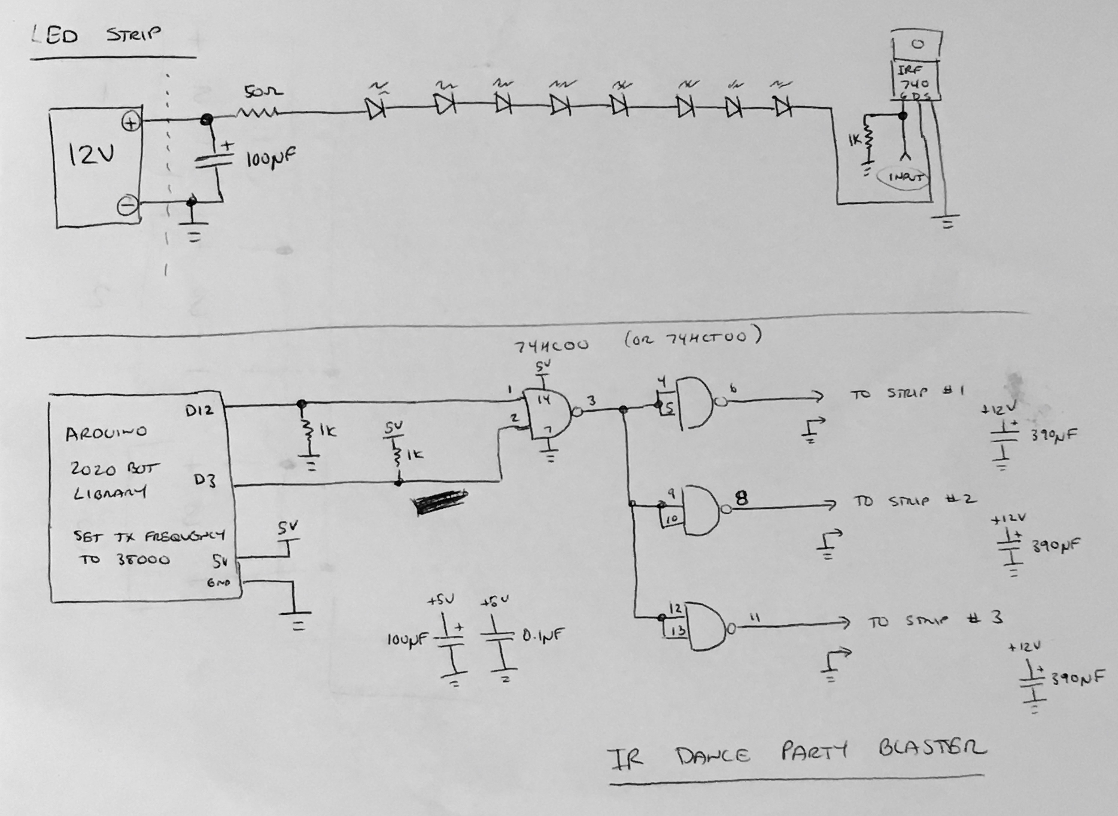
Ignoring the firmware magic for now, and assuming we actually can find a beat, the next hardware task was generating the IR codes and blasting them out to the robots. As we mentioned before, the 2020 Bot has an IR library that works well with its remote control, and includes matching transmitter code. So, we decided to simply use that library and generate a button press for every beat.
The IR library uses two pins for transmission. One generates the 38KHz tone, while the other performs the code modulation. For the 2020 Bot, these pins connect directly to each side of an IR LED through a resistor (note that the 2020 Bot does some funky stuff with open collector driving). In our project, we want the two signals combined so we can send them to remote IR LED panels. This is done with a 74HC00 NAND gate.
Each LED bar is powered from 12V. The IR LEDs we had kicking around had forward voltage drops of about 1.4V. At 12V, we could drive 8 LEDs in series (8 x 1.4V = 11.2V), dropping through a 50 ohm series resistor. This gives us LED current of 16mA (50 ohms / 0.8V).
Our parts cabinet had a boat load of IRF740 N-Channel MOSFETs which are way overkill for 16mA drive, but they'll do the job.
We added extra bulk capacitance around, figuring the panels would be wired at a distance from the power supply.
Here's the prototype IR modulation combiner and LED strip schematics:
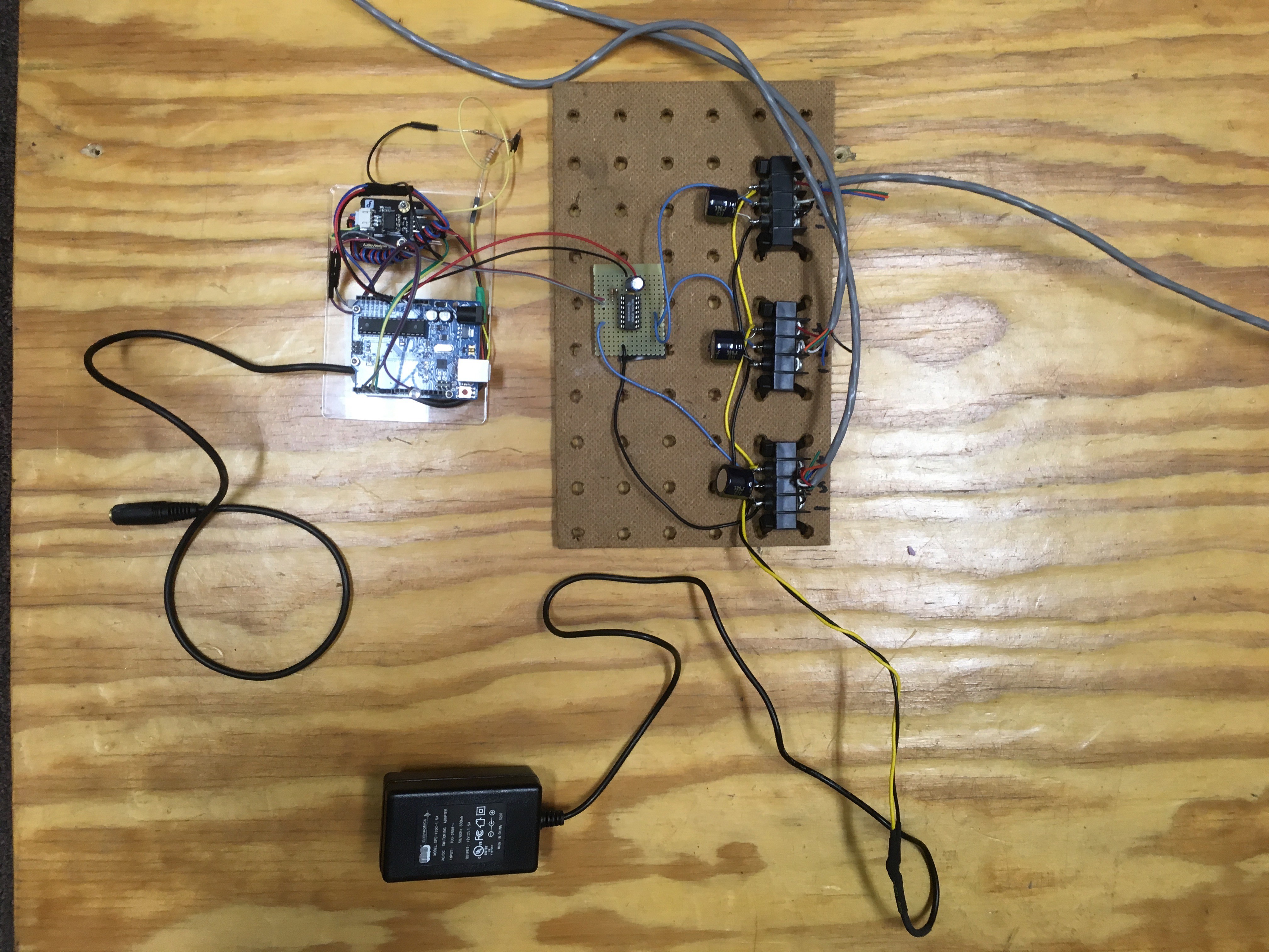
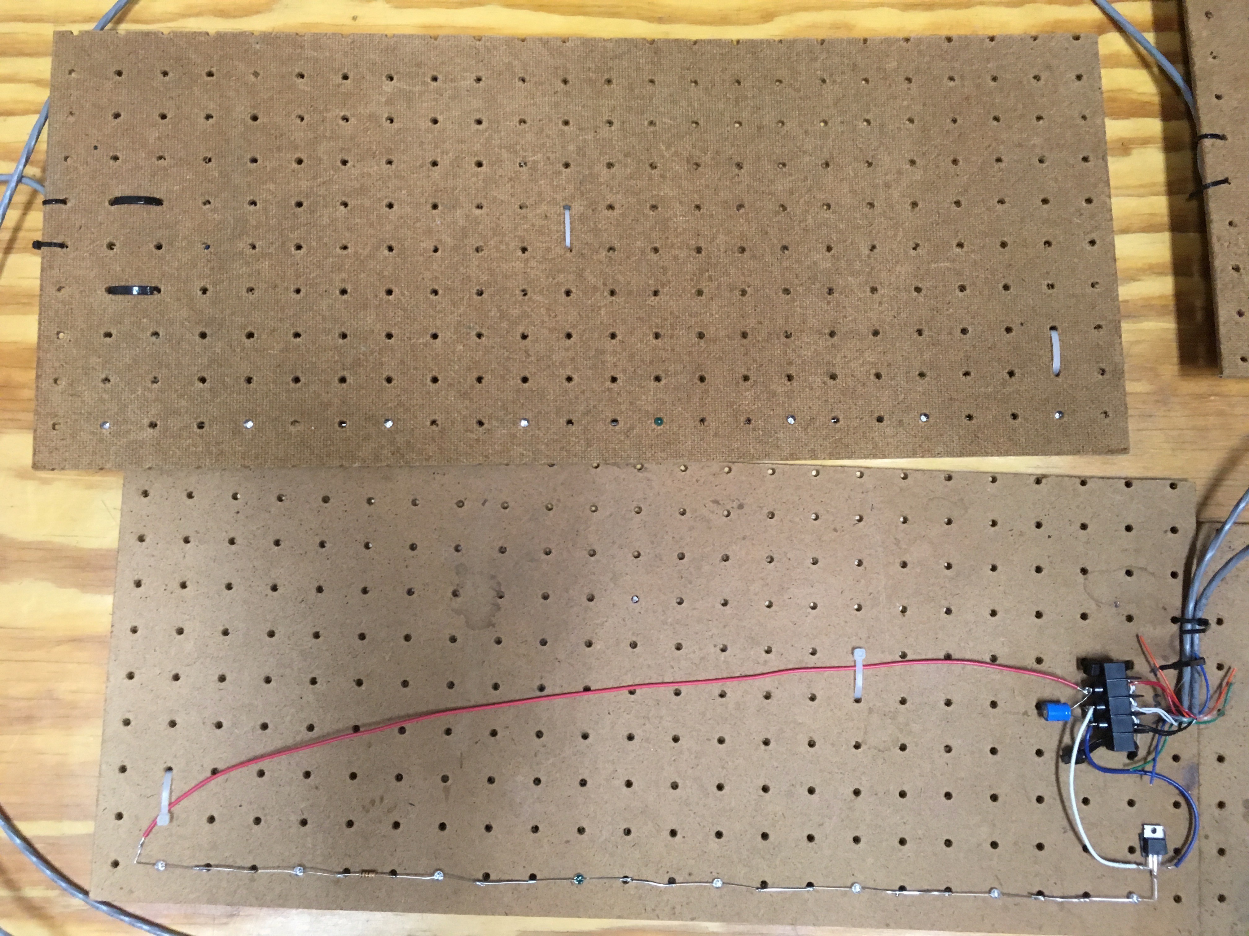
And, here are pictures of our prototype system:
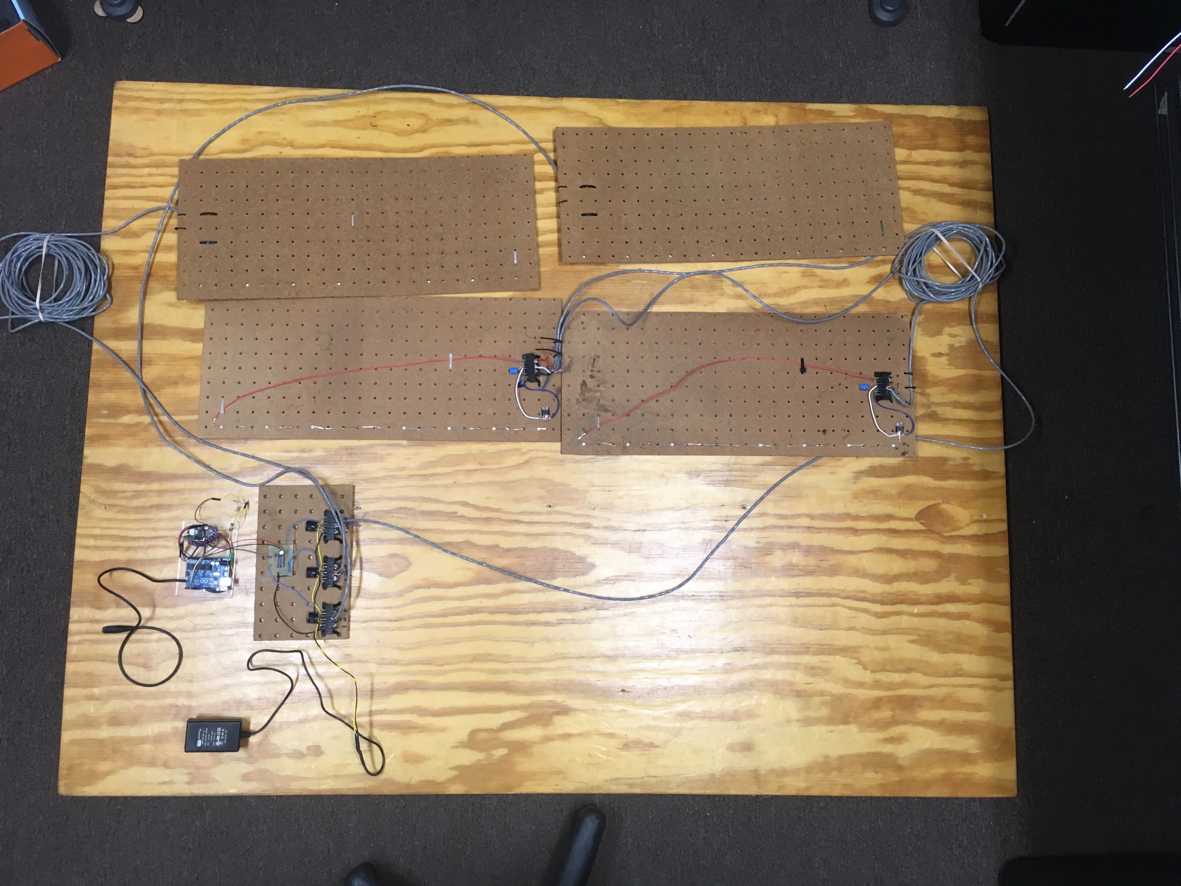
Arduino Beat Detector and IR Modulator:
LED Panels (note that we used 7 IR LEDs and 1 Green LED, that way we could see if the panel was working):
In our next post, we'll get into some code...
Discussions
Become a Hackaday.io Member
Create an account to leave a comment. Already have an account? Log In.