 Jay Francis
We've been working on the "less hacked" version of the Beat Blaster design. Originally, we were going to take almost exactly what we did on Arduino Day and just turn it into to PCBs - one for the Beat Blaster and one for the IR Panels. Keeping things simple, we were leaning towards either sticking an Arduino Nano on the PCB, or dropping an ATMega328 right down.
And then we started thinking about other features we might want to add (yes, the bane of all projects that you're trying to complete quickly... but you know what? This is just for fun! What the heck...).
Instead of an Arduino Nano, we decided to go for an ESP32. Our feature creep list included:
a) could also blast the beat and frequency info over UDP via WiFi for smarter robots
b) could serve up a spiffy web app from the ESP32 to adjust parameters, look at the spectrum, etc.
c) while we have a web app, could add “show us your moves” buttons to the app to send dance move commands
d) somewhat smarter robots could also register with the beat blaster, so we can do things like “hey robot X, show us your moves”
e) opens up a whole set of other possibilities for dance party accessories… connected lights that listen to the music (via UDP), synced strobes, robots with controllable freakin’ lasers on their heads, etc.
So, that's where we're at. We have block diagrams and description below.
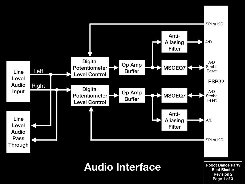
The audio interface will be stereo and we'll have two complete paths into the ESP32. One of the issues we had in the original design was getting the sound levels just right. With this design, we'll include digital level control and be able to monitor the levels. Alternatively, if the ESP32 turns out to be fast enough (which we think it will be), we might just decide to do digital processing of the analog signals directly and eliminate the MSGEQ7 chips. For now, the design will support both options.
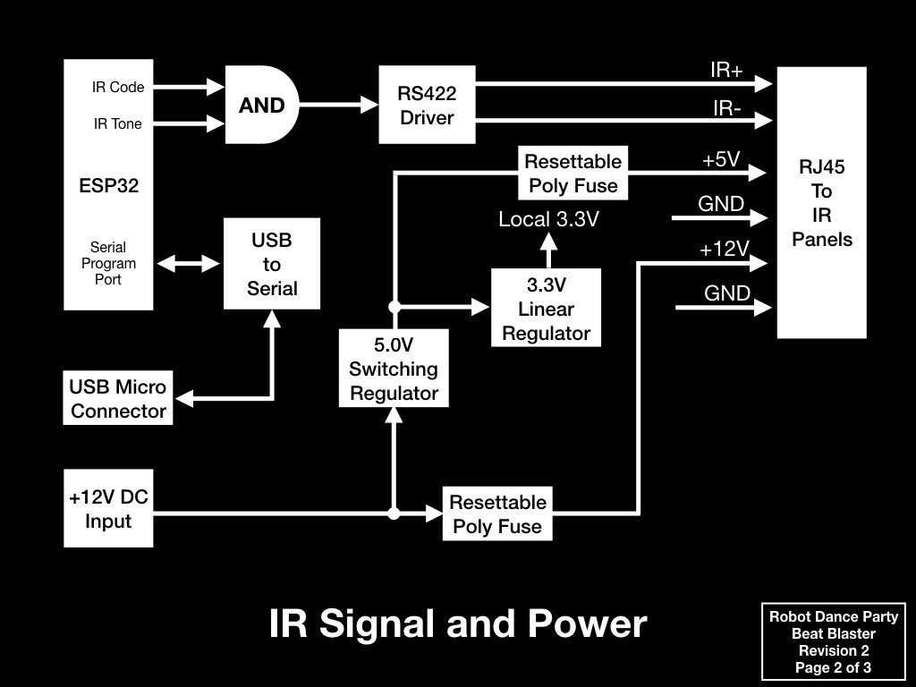
DC power input will still be +12V. This will pass through a poly fuse and out to the IR Panels. A switching regulator will generate +5V from the +12V input and +5V will also pass through a poly fuse and out the IR Panels. A +3.3V linear regulator will take care of our local power needs.
For the IR signals, the IR Code and IR Tone will still be generated separately and combined with an AND gate. Instead of sending pure logic levels out to the panels, an RS422 differential driver will be used. This gets us a bit more noise tolerance and since RS422 receivers can be multi drop, we should be able to daisy chain panels (instead of the original star topology).
Using RJ45 connectors and generic ethernet cables makes for simple hook-ups.
Depending on whether or not we use an off the shelf ESP32 dev module, or if we drop an ESP32 WROOM module down raw, a USB to Serial converter may be required.
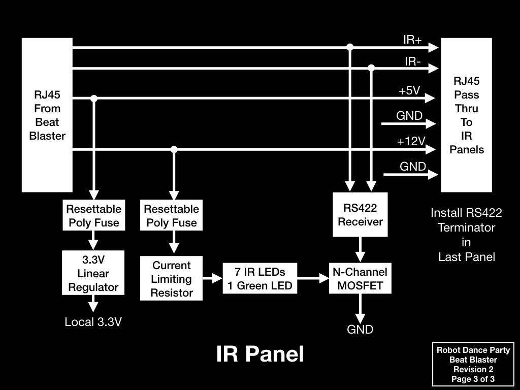
Finally, we have the IR Panels. Each will have a pass through RJ45 to make daisy chaining panels easy. Local +3.3V is generated from +5V (doing this is better than trying to send +3.3V around to all the panels... it will handle minor voltage drops and noise better).
The LED circuit is similar to the original with the addition of the RS422 receiver. +12V passes through a poly fuse, current limiting resistor, and 8 LEDs in series (7 IR LEDs and 1 Green LED so we can see that the panel is working). The MOSFET switches the LED chain to ground based on the received IR signal.
Since RS422 should be terminated, the last panel in the chain will either need a terminator installed in the pass thru connector, or, we'll design a terminator on each board that can be connected via a jumper.
That's it for now. The next step is to get some hardware designed so all the software people on the project get to have some fun!
Discussions
Become a Hackaday.io Member
Create an account to leave a comment. Already have an account? Log In.