 Jay Phantom
Materials Needed:
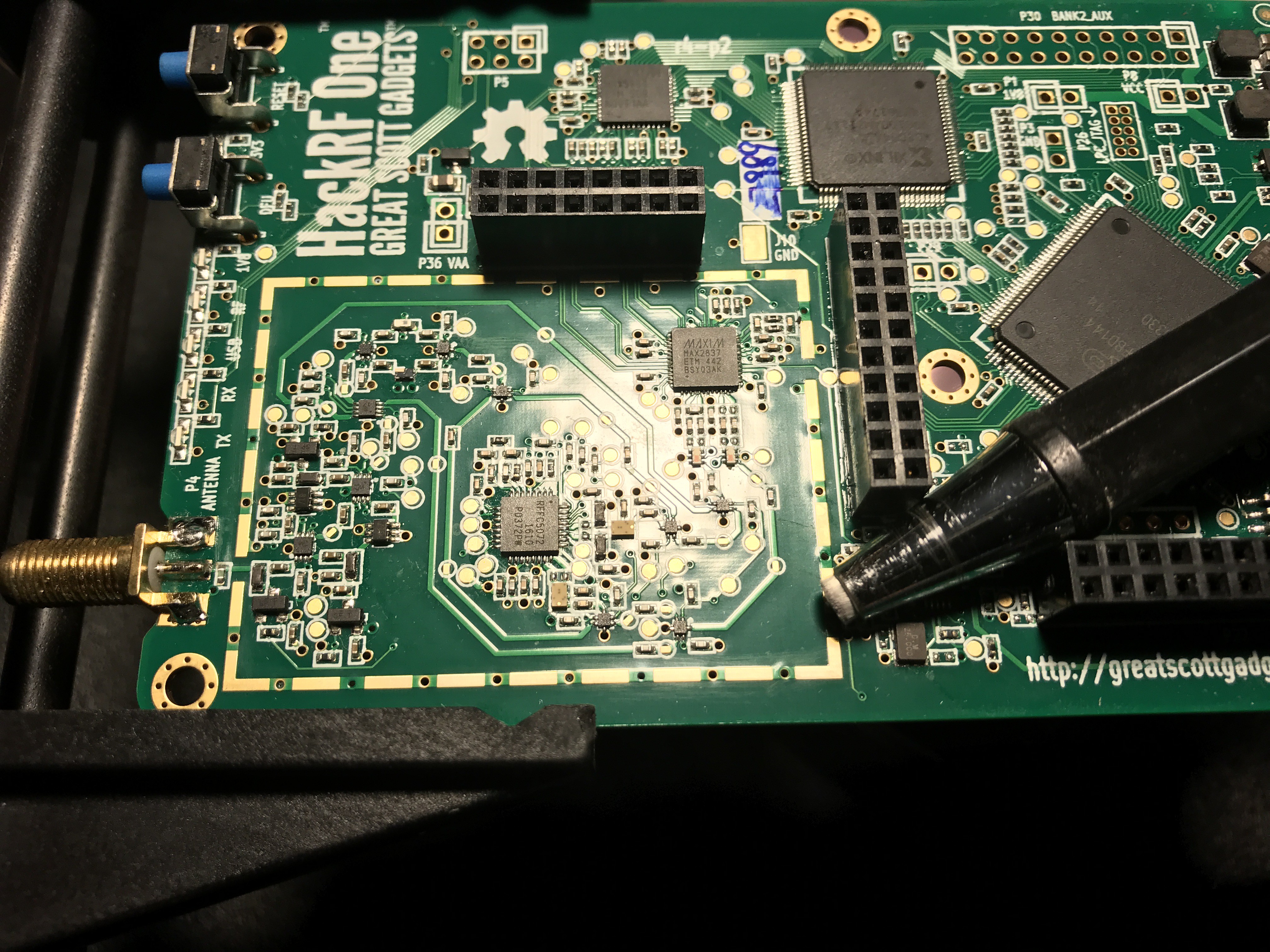
- HackRF One from Great Scott Gadgets.
- Nooelec's HackRF Shielding Kit.
- ESD safe soldering iron.
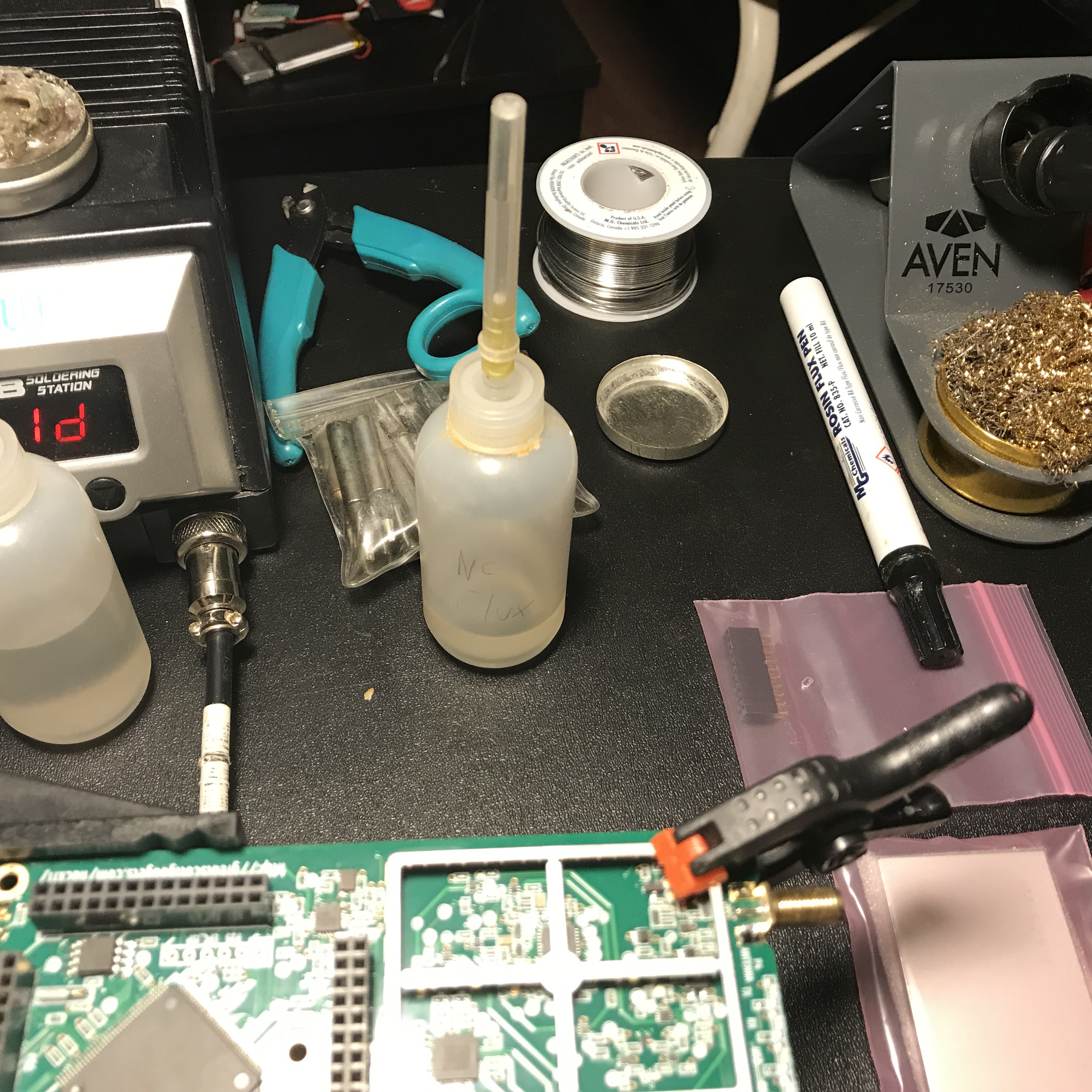
- No-Clean liquid flux.
- Your favorite/best solder.
- Your preferred flux cleaner.
- Small Plastic Clamp
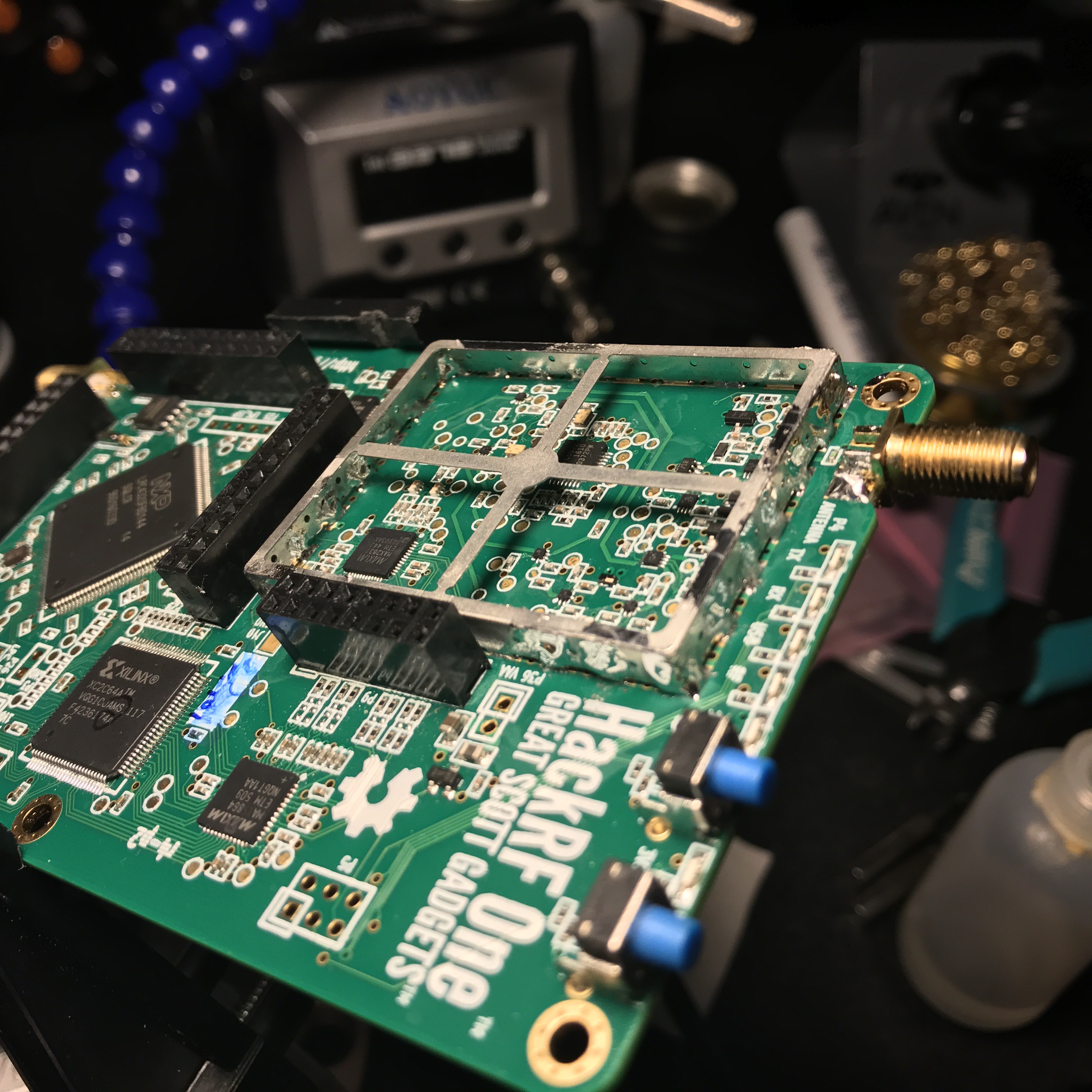
This is a tutorial on how to install the NooElec HackRF Shielding Kit.
Already have an account? Log in.
To make the experience fit your profile, pick a username and tell us what interests you.
Materials Needed:
I just have to add the SnR figures, and waterfall images to compare the device with and without the shield. Those will happen in the next day or so. Thanks all!
I used no-clean liquid flux for this build instead of the usual rosin flux, as it's way way easier to clean off of a board with small components, or extra small spaces it can collect in.
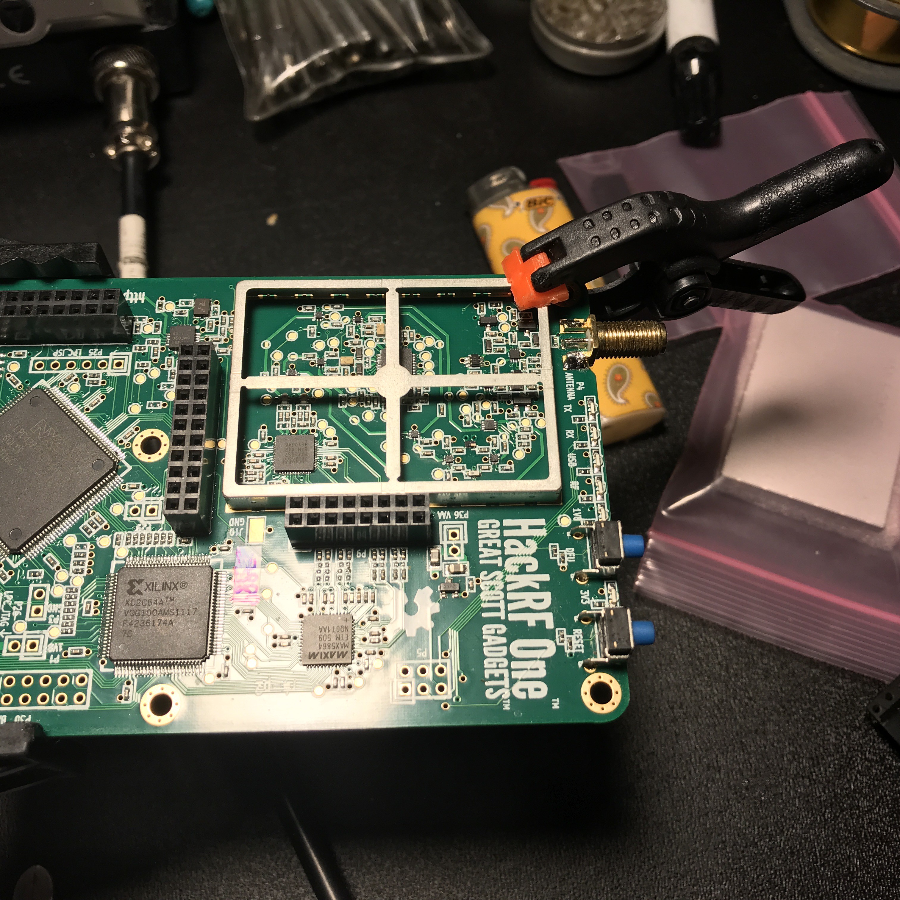
You will also want to find a light clamp to hold the shield down until you tack a couple of the corners.
I prepped the board by wiping off any dust, and old flux with alcohol, or flux remover on a small cotton cloth, and then used my fiberglass abrasion pen to rough up the areas I was going to solder. After that I washed it again in flux remover to remove any dust from the abrasion process. This provides microscopic etches in the copper that makes for a tighter molecular bond with the solder.
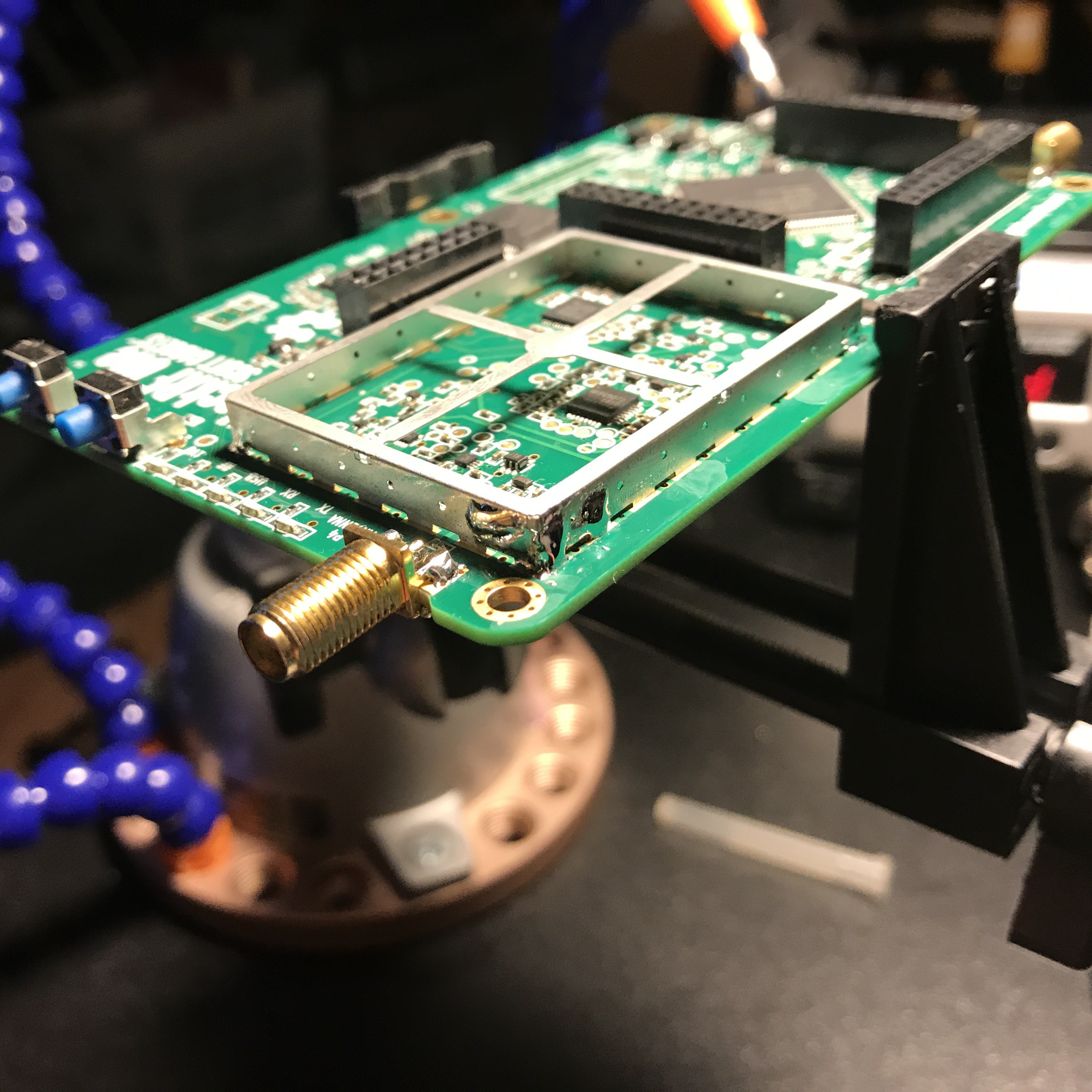
Before you solder anything, place the shield on the dashed copper lines, and decide how you are going to secure it to the board for soldering.
Use a light clamp to secure the shielding frame to the PCB. If its too strong it will bend the frame. I used a small plastic clamp with rubber tips you can get at any hardware store.
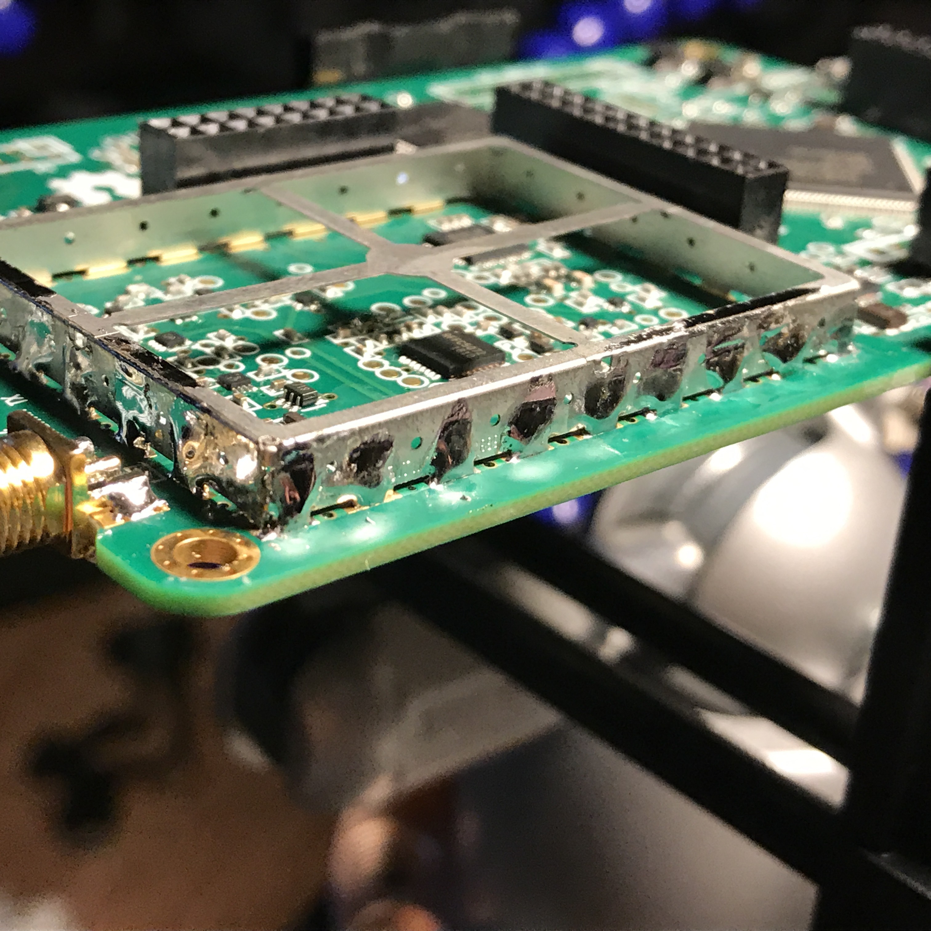
I used a wide, flat-head type soldering iron tip for maximum heat transference. With my rig, 750 degrees F melted the solder fast, and transferred enough heat to the shield body to create a good bond. No more than 4 to 5 seconds of heat per weld. There are some heat sensitive components close to the edge of the shield in a couple of places, be extra careful about heat in those areas, as you may accidentally unseat one of the small resistors or caps in the RF section.
Starting with the corners, add flux to the tab you're going to solder. Using the wide flat screwdriver shaped tip for my iron, add a bit of solder to the tip, and press between the PCB and the shielding frame. You wanna heat the frame and the copper pad at the same time, so that the solder flows to both. I did it one tab at a time, and let it cool between tabs. I didn't wanna risk heat damage to the sensitive RF section.
Also, for some of them due to clearance with other board components, I had to solder the tabs from the inside of the frame. See the pics.


 jean.perardel
 Ian Hanschen
 mircemk
 Brad Spry
It should be noted that while both these items are still for sale. The most updated rev of the Hack RF already have this implemented. Oh well for me and duh I suppose.