 Danny FR
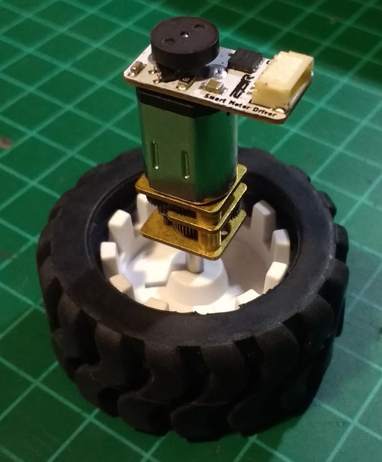
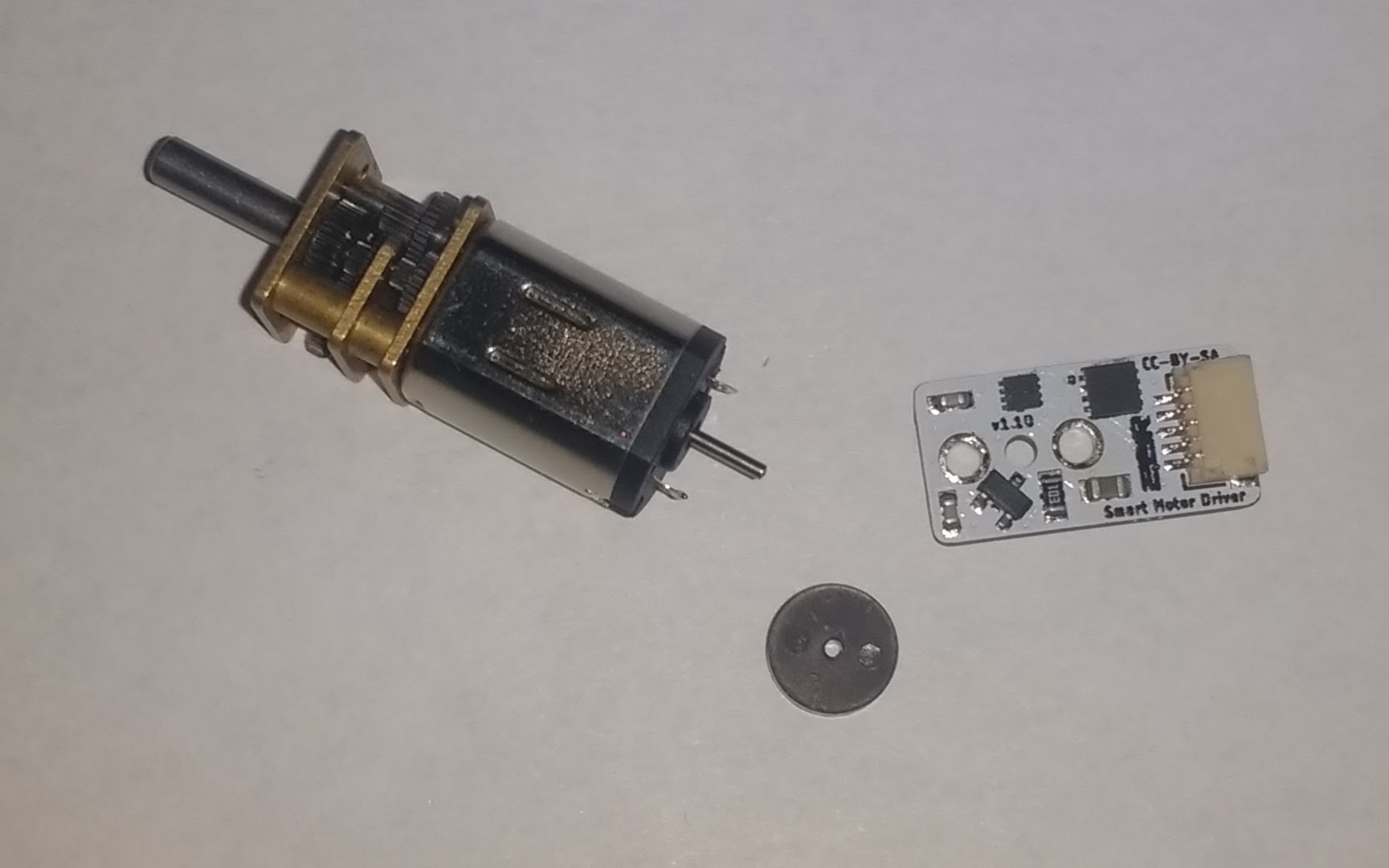
This is the Smart Motor Driver (aka SAMI) designed to run a micro gearmotor, the objective of this board is to be able to implement a PID control easily over this motors with the corresponding RPM feedback using a hall effect sensor. So it has his own microcontroller and H bridge on board to be capable of do the work by itself.
The host microcontroller (or any system that can use I2C) communicates by I2C in order to give the commands to the smart driver module, this includes speed and direction of the motor. The module will automatically implement the PID to maintain the speed and apply more/less power dynamically in the motor to archive that.

Also the control module is capable of driving the motor for a desired distance or angle and then stop when is reached. For doing that you must specify the diameter of your wheel and the gearbox relation.
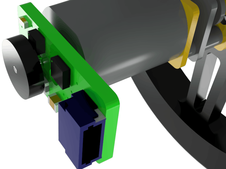
To sense the speed of the motor I used a magnetic encoder disk, it is polarized along the surface of the disk. So the hall effect sensor can detect the changes in the magnetic field of the disk and send the signal to the microcontroller. Then using the timer and interrupts we will calculate the RPM of the motor in second plane, so the microcontroller is free to run a PID control algorithm and handle the communication with the host.
The main idea is to use it in robotics, so by using this modules to control the wheels of the robot it can be possible to make precise movements no matter the surface , the battery charge or even if the robot changes its weight!!!
Also it protects the gears from stripping due to a sudden acceleration or braking and will avoid the battery to trip the protection circuit caused by a current rush. So your precious motors will be safe!
An Arduino library is available for easy use of SAMI, and you can plug a lot of motors fast and easy.
Features:
- Simple installation at the back of a micro DC motor.
- Can control speed and direction of a motor.
- Stops automatically when distance or angle is reached.
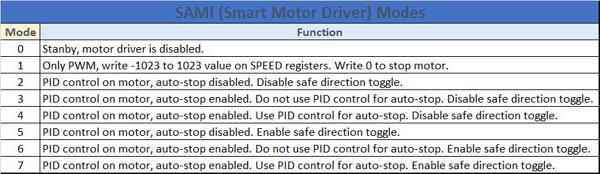
- Multiple control modes, including simple PWM or PID with or without auto-stop. Plus a safe direction toggle option.
- Works over I2C. The address can be changed by software.
- Control a lot of motors, up to 128 modules can be in the same single I2C bus.
- Internal pull-ups for I2C can be enabled/disabled by software.
- Configurations can be saved on EEPROM.
- Read the actual speed of the motor and check if a fail happens.
- Fully configurable.
- Easy to use high precision motor control.
- Small package, just 2 cm x 1 cm.
- Arduino library available.
Specs:
- Motor voltage up to 11v.
- Maximum motor continuous current as high as 1.7A and 1.8A peak.
- Logic voltage from 3v to 5v. (1.8v range to being confirmed later after testing it)
- Default I2C address is 0x24.
- Protection against overcurrent and overtemperature.
- To RESET default I2C address connect MCLR pad to GND at power up.
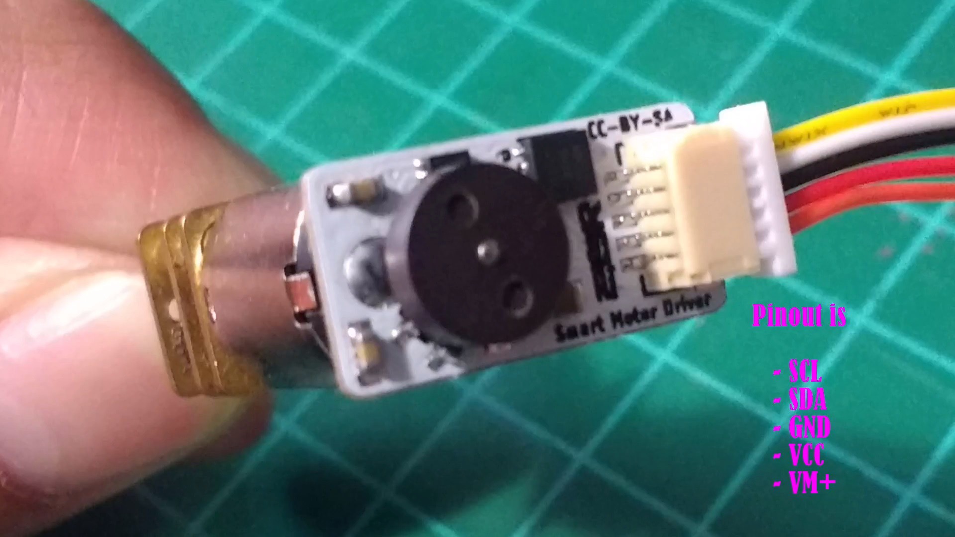
- Standart 1mm 5 pin JST connector.
Benefits:
- Independent motor control.
- Smoother and precise movements.
- Avoid breaking your motors.
- Easy to use solution.
- Built in motor speed feedback.
- Highly responsive PID control to keep motor speed constant.
- Avoid abrupt current peaks that can damage your power supply or battery.
- Automatically stops at desired travel distance or angle if specified.
- Powerful navigation solution for robots when combined with other sensors like an IMU.
- Open source design.
Installation:
For install SAMI to a motor you only need to solder it and place the encoder as shown in the next video:
IMPORTANT: your motor should have an extended shaft in order to allow placing the encoder!!!!
Pinout:
JST connector pinout to communicate with SAMI.
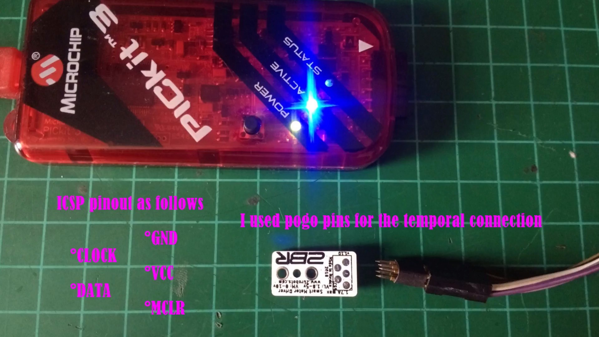
ICSP pads for updating firmware. MCLR can be used to restore I2C address of the module.
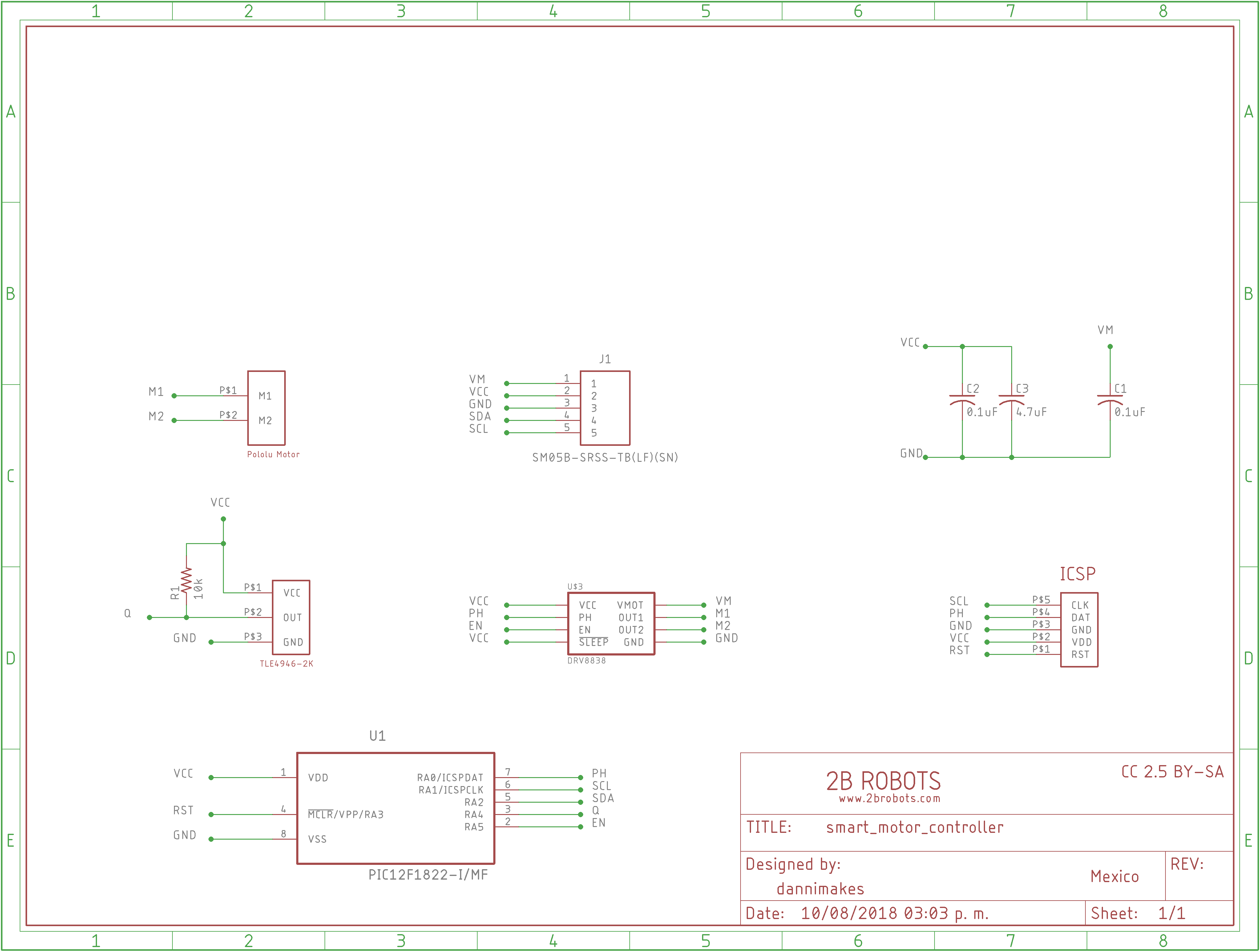
Schematic:
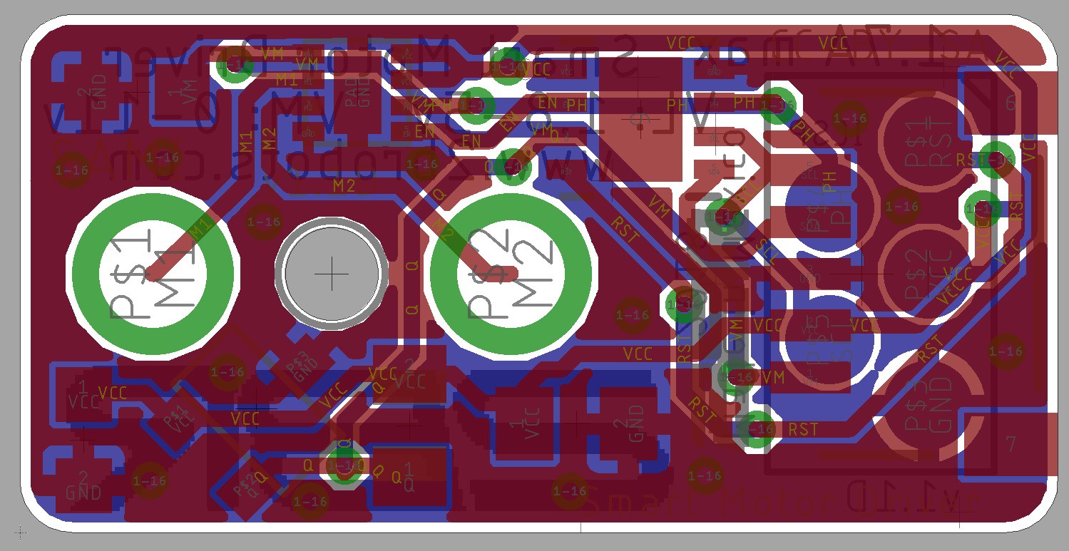
PCB layout:
The PCB is 0.8mm thick and it measures 10 mm x 20 mm. Is a double layer board.
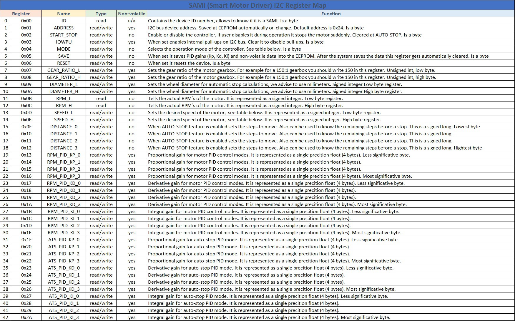
I2C registers:
Operation modes:
This is a project under development, so please follow me get updates :) This is an open source project, so if you have any ideas to improve it you are welcome. Also you can adapt the hardware and software to run a bigger motor, add a second channel to the encoder or even run a stepper motor instead!!!

This work is licensed under a Creative Commons Attribution-ShareAlike 2.0 Generic License.