 igorfonseca83
There are several ways to use this tutorial. You can use it to:
- Learn how to track and update your asset values for a particular currency using a Google spreadsheet;
- Program an ESP32 using the Arduino IDE;
- Read values from a Google spreadsheet using an ESP32 device;
- Learn to 3d print using flexible filaments;
- Practice your electronics and soldering skills, etc;
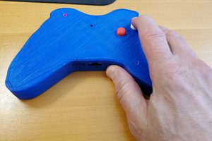
You can use part of this tutorial to create your own gadgets or follow it to the end and produce your own wallet.
This tutorial is divided as follows:
| Step | Subject | Topics |
|---|---|---|
| 1 | Tools and materials | Tools and materials used in this project |
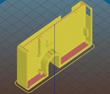
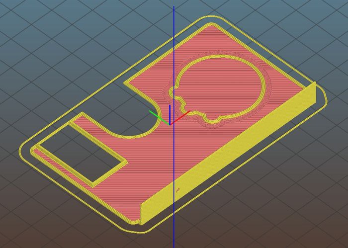
| 2-3 | 3D printing | How to 3D model and 3D print the gadget |
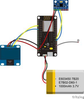
| 4-5 | Electronics | How to wire up the circuits |
| 6-7 | Google Spreadsheet | How to create a Google Spreadsheet an share it with your gadget |
| 8-12 | Coding | How to program a ESP32 using Arduino IDE |
There are some awesome tutorials on how to track the prices of crypto currencies. This one served as a inspiration for this project: https://www.instructables.com/id/Simple-10-Crypto-Currency-Display/
Liked that projects? Please consider supporting my future projects with a small Bitcoin donation! :D BTC Deposit Address: 1FiWFYSjRaL7sLdr5wr6h86QkMA6pQxkXJ
For this project, the following tools were used:
- 3D printer. I used it to print my wallet and produce a case for the electronics (with regular PLA filament). You can find some inexpesive 3D printers online that will work just fine for this project (link).
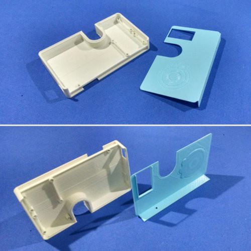
- 1.75mm PLA filament (link / link / link). I used rigid white and blue PLA filament for printing the case where the electronics are encased and protected. This way they won't get crushed if I sit with on my wallet, or if it accidenty falls on the floor.
- Solder iron and wire. I needed it to solder some wires between the electronic components, as you'll se later.
- Super glue. The 3D design was printed in different parts. I used some super glue to stick them together.
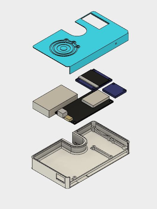
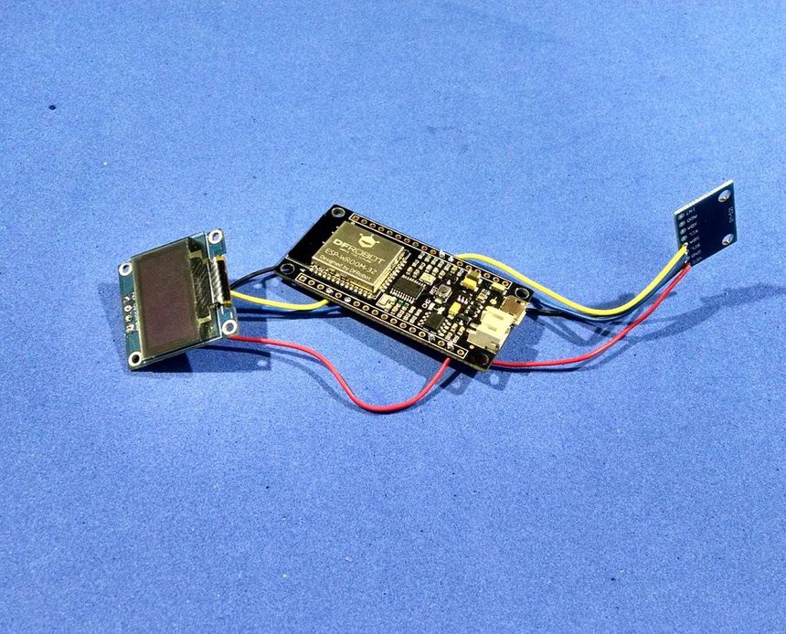
I used the following hardware parts for my project:
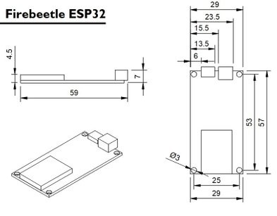
- Firebeetle ESP32 dev board (link). Firebeetle ESP32 board is really easy to use and program using Arduino IDE. It has built-in Bluetooth and Wi-Fi modules, so you can use it in a variaty of projects. It has a connector for a 3.7V battery, which was really usefull for assembling this project. I has also a built-in battery charger. It will recharge the battery when connected to an USB plug. You can also use other ESP32 based boards (link / link), or ESP8266 ones (link / link / link) if you wish. Deppending on the board you choose, it would be a little more difficult to connect and recharge the battery. The dimensions of the case will also need to be verified.
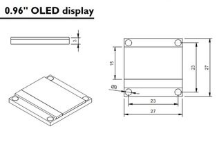
- OLED display (link / link). It was connected to the ESP board, for displaying the values obtained from Google Spreadsheet.
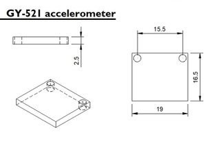
- GY-521 accelerometer (link / link). It was used as a step counter.
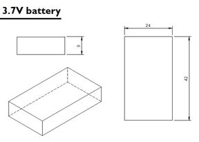
- 3.7V battery (link / link). I used to power the whole circuit.
- Wires.
- Micro USB cable.
- M2x6mm bolts (x9)
- M2x1.5mm nuts (x5)
The links above are only a suggestion of where you can find the items used in this tutorial (and maybe support my future tutorials). Feel free to search for them elsewhere and buy at your favorite local or online store.
As it was said before, some ESP dev boards won't have a built-in battery connector (and charger). In that case, you'll need an external battery charging module (a TP4056 (link / link), for instance). It will possibly require a mini USB cable for the connection between the charger and an USB port. Did you know you can buy a Anet A8 for only $155.99? Get yours at Gearbest:http://bit.ly/2kqVOdO

 Andrew Mitz
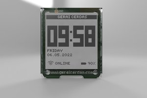
 Mauro Pichiliani