 Hulk
HulkHi Everyone, I am back again with this new tutorial.
In this tutorial I am going to show you how to charge a Lithium 18650 Cell using TP4056 chip utilizing the solar energy or simply the SUN.
Wouldn’t it be really cool if you can charge your mobile phones battery using the sun instead of a USB charger. You can also use this project as a DIY portable power bank.
The total cost of this project excluding the battery is just under $5. The battery will addup another $4 to $5 bucks. So the total cost of the project is some what around $10. All components are available on my website for sale for really good price, the link is in the description below.
Step 1: Hardware Requirement

For this project we need:
- A 5v Solar Cell (make sure it is 5v and not anything less than that)
- A general purpose circuit board
- A 1N4007 High Voltage, High Current Rated Diode (for reverse voltage protection). This diode is rated at forward current of 1A with peak reverse voltage rating of 1000V.
- Copper Wire
- 2x PCB Screw Terminal Blocks
- A 18650 Battery Holder
- A 3.7V 18650 Battery
- A TP4056 battery protection board (with or without the protection IC)
- A 5 V power booster
- Some connecting cables
- and general soldering equipments
Step 2: How the TP4056 Work

Looking at this board we can see that it has the TP4056 chip along with few other components of our interest.
There are two LEDs on board one red and one blue. The red one comes on when it is charging and the blue one comes on when the charging is done. Then there is this mini USB connector to charge the battery from an external USB charger. There are also these two points where you can solder your own charging unit. These points are marked as IN- and IN+ We will be utilizing these two point to power this board. The battery will be connected to these two point marked as BAT+ and BAT- (pretty mush self explanatory) The board requires an input voltage of 4.5 to 5.5v to charge the battery
There are two versions of this board available in the market. One with battery discharge protection module and one without it. Both boards offer 1A charging current and then cut off when finished.
Furthermore, the one with protection switches the load off when the battery voltage drops below 2.4V to protect the cell from running at too low (such as on a cloudy day) - and also protects against over-voltage and reverse polarity connection (it will usually destroy itself instead of the battery) however please check you have it connected correctly the first time.
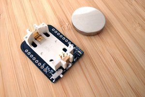
Step 3: Copper Legs
These boards gets really hot so I will be soldering them a bit above the circuit board.
To achieve this I am going to use a hard copper wire to make legs of the circuit board. I will then be sliding the unit on the legs and will solder them all together. I will put 4 copper wires to make 4 legs of this circuit board. You can also use - Male Breakable Pin Headers instead of the copper wire to achieve this.
Step 4: Assembly

The assembly is very simple.
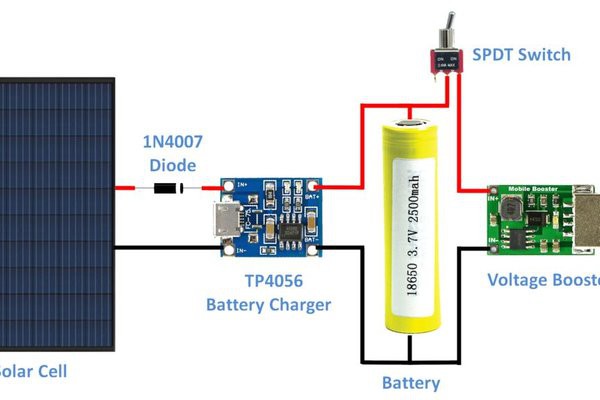
The solar cell is connected to the TP4056 battery charging board's IN+ and IN- respectively. A diode is inserted at the positive end for the reverse voltage protection. Then the BAT+ and BAT- of the board is connected to the +ve and -ve ends of the battery. (That all we need for charging the battery). Now to power an Arduino board we need to boost up the output to 5v. So, we are adding a 5v voltage booster to this circuit. Connect the -ve end of the battery to the IN- of the booster and +ve to IN+ by adding a switch in between. OK, now lets have a look at what I have made. - I have connected the booster board straight to the charger however I will recommend putting a SPDT switch there. So when the device is charging the battery its only charging and not getting used
Solar cells are connected to the input of the lithium battery charger (TP4056), whose output is connected to the 18560 lithium battery. A 5V step-up voltage booster is also connected to the battery and is used to convert from...
 Jasper Sikken
 Brian Gilbert
 deʃhipu