 Hulk
HulkStep 1: Basics

A Relay is a large mechanical switch, which is toggled on or off by energizing a coil.
Depending on the operating principle and structural features relays are of different types, such as:
1. Electromagnetic Relays
2. Solid State Relays
3. Thermal Relays
4. Power Varied Relays
5. Reed Relays
6. Hybrid Relays
7. Multi-dimensional Relays and so on, with varied ratings, sizes and applications.
However, in this tutorial we will only be discussing about an electromagnetic relays.
Guide to Different Types of Relays:
1. https://en.wikipedia.org/wiki/Relay
2. https://www.elprocus.com/different-types-of-relays...
Step 2: My Relay (SRD-05VDC-SL-C)
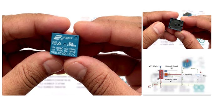
The relay I am looking at is a SRD-05VDC-SL-C. It is very popular relay among Arduino and DIY electronics hobbyists.
This relay has 5 pins. 2 for the coil. Middle one is COM (common) and the rest of the two are called NO (Normally Open) and NC (Normally Close). When current flows through the coil of the relay, a magnetic field is created that causes a ferrous armature to move, either making or breaking an electrical connection. When the electromagnet is energized the NO is the one which is on and NC is the one which is off. When the coil is de-energized the electromagnetic force disappears and the armature moves back to the original position turning on the NC contact. The closing and releasing of the contacts results in powering on and off of the circuits.
Now, if we look at the top of the relay the first thing we see is SONGLE, it is the name of the manufacturer. Then we see the "Current and Voltage Rating": it is the maximum current and/or voltage that can be passed through the switch. It starts from 10A@250VAC and goes down till 10A@28VDC Finally the bottom bit says: SRD-05VDC-SL-C SRD: is the model of relay. 05VDC: Also known as "Nominal Coil Voltage" or "Relay Activation Voltage", it is the voltage necessary for the coil to activate the relay.
S: Stands for "Sealed Type" structure
L: is the "Coil Sensitivity" which is 0.36W
C: tells us about the contact form
I have attached the datasheet of the relay for more information.http://old.ghielectronics.com/downloads/man/20084...
Step 3: Getting Hands on a Relay
Let’s start by determining the relay coil pins.
You can do it either by connecting a multimeter to resistance measuring mode with a scale of 1000 ohm (since the coil resistance normally ranges between 50 ohm and 1000 ohm) or by using a battery. This relay has 'no' polarity marked on it since the internal suppressing diode is not present in it. Hence, the positive output of DC power supply can be connected to any one of the coil pins while negative output of DC power supply will be connected to the other pin of the coil or vice versa. If we connect our battery to the right pins you can actually hear the *clicking* sound when the switch turns on.
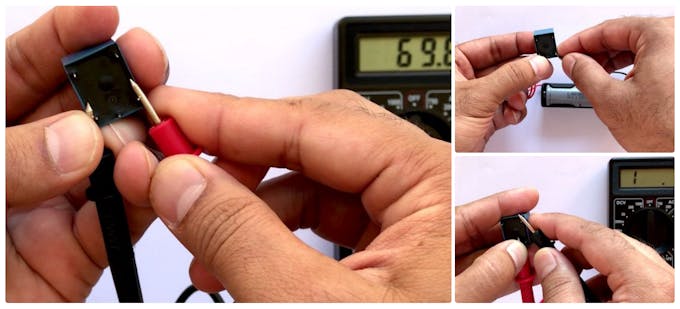
If you ever get confused in figuring out which one is NO and which one is NC pin, follow the steps below to easily determine that:
- Set the multimeter to resistance measuring mode.
- Turn the relay upside-down to see pins located at its bottom part.
- Now connect one on the multimeter's probe to the pin in between the coils (Common Pin)
- Then connect the other probe one by one to the remaining 2 pins.
Only one of the pins will complete the circuit and will show activity on the multimeter.
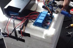
Step 4: Arduino and a Relay

* The question is "Why to use a relay with an Arduino?"
A micro controller's GPIO (general purpose input/output) pins cannot handle higher power devices. A LED is easy enough, but large power items such as light bulbs, motors, pumps or fans required more sneaky circuitry. You can use a 5V relay to switch the 120-240V current and use the Arduino to control the relay.
* A relay basically allows a relatively low voltage to easily control higher power circuits. A relay accomplishes this by using the 5V outputted from an Arduino pin to energize the electromagnet which in turn closes an internal, physical switch to turn on or off a...
 UTSOURCE
 Shreyasvi Natraj