Close
0%
0%

3 Blink Modification for SAAB 9-5

Activates the blinkers 3 times from just a touch on the indicator stalk for 1999 SAAB 9-5

Similar projects worth following
Most modern cars have a function that activates the blinkers 3 times from just a touch on the indicator stalk. My 1999 SAAB 9-5 doesn't have this neat function so I have set out to give it to it.

The 1999 SAAB 9-5 blinkers are controlled by the DICE module  which reads the Indicator switch position and commands the blinkers appropriately.

The plan will be to implement something that will read the blinker indicator switch and if its intermittently operated than keep the blinkers on for 3 seconds.

After some recent discussions with  Lars Rune Bjørnevik

he kindly rewrote the code to enable it to be used as class library which will allow the code to be used in conjunction with other Arduino MEGA  projects in your car.

He has provided 3 files

IndicatorHandler.cpp

IndicatorHandler.h

ReadMe.md

The readme file contains the following usage instructions


Usage:
 // Create a sub-directory called "IndicatiorHandler" where the .ino file resides
 // Copy the .h and .cpp file into a sub-directory called "IndicatiorHandler"  
#include "IndicatiorHandler.h"  

 // Global init:
 IndicatiorHandler indicator;

 // In setup()
 indicator.Enable();

 // In loop()
 indicator.IndicatiorUpdate();

SAABBlinker5.ino

Stand alone file for Arduino Nano.

ino - 5.39 kB - 05/29/2018 at 13:20

Download

IndicatiorHandler.cpp

Class Files for use with Arduino MEGA created by Lars Rune Bjørnevik

cpp - 5.46 kB - 02/24/2022 at 10:20

Download

IndicatiorHandler.h

Class Files for use with Arduino MEGA created by Lars Rune Bjørnevik

h - 1.96 kB - 02/24/2022 at 10:20

Download

ReadMe.md

Usage details for Arduino MEGA class files created by Lars Rune Bjørnevik

markdown - 405.00 bytes - 02/24/2022 at 10:20

Download

  • Installed and working

    Saabman05/31/2018 at 11:50 0 comments

    getting the pro micro installed in the DICE module was rather straight forward with power and signals all coming straight of the multiplexer. The microcontroler board is just stuck to the top of the mux with double sided tape. 

  • DICE connections

    Saabman05/29/2018 at 12:33 0 comments

    I just hooked the DICE up without its case and made some measurements and to confirm I had the right pins.

    Yep it all looks good - Ive updated the image with markings for the pick up points for the blinkers and the power supply.

    Ill hopefully get a chance later today to solder the Arduino in and give it a go.

    The multiplexer (74HC151) second from the left is the chip we need to attach to.

    Pin 1 Left blinker input

    Pin 2 Right blinker input

    Pin 16 +5V

    Pin 8 0V

  • Firtst Attempt

    Saabman05/29/2018 at 12:30 0 comments

    After the blinker has been held on for while when it turns off if there is a bit of contact bounce it will latch the blinker for 3 seconds. its not a show stopper but Id like to rectify it. In reality it may rarely occur as the blinker switch contacts are a bit more robust than my dodgey piece of wire. Ive been playing around with some techniques to debounce it but nothing is really working out.

    It may be that I rewrite without using interrupts and poll the input but ill leave it like it is at the moment if you want to have a play here is what I have so far.

    /* Implementation of 3 second "auto" blinkers for SAAB9-5 by SAABAus Sept 2017 
     * uses pins 2 and 3 as inputs untill required than change to outputs to hold the blinker on.
     */
    
    int Blink_left = 2;                     //  Left Blinker switch on pin 2
    int Blink_right = 3;                    //  Right Blinker Switch on Pin 3
    int debounceTime = 200;                 //  debounce lock out time
    bool Blink_left_status = 0;             //  Store for the current status of the Left blinker
    bool Blink_right_status = 0;            //  Store for the Current Status of the Right Blinker
    unsigned long debounce = 0;             //  
    unsigned long trigger = 0;
    unsigned long Time_start = 0;
    unsigned long OnTime = 3000;             // Time blinkers stay on for in ms 


    void Right_Blink ()
    {
      if (millis()- debounce > debounceTime)
      {
      if (Blink_left_status == 1)           //check to see if the left blinker is on
       {
        Blink_left_status = 0;             // if it is turn it off
        digitalWrite(Blink_left, LOW);
        pinMode (Blink_left, INPUT);
       }   
       else
       {
        Blink_right_status = 1;             // if the left blinker wasnt on turn on the right blinker
        pinMode (Blink_right, OUTPUT);      // set the right pin to an output
        digitalWrite (Blink_right, HIGH);   // turn on the right blinker
        Time_start = millis();              // Starts the 3 second timer
       }
       debounce = millis();
      }
    }
    
    void Left_Blink ()
    {
      
      if (millis() - debounce > debounceTime)
      {
        
          if (Blink_right_status == 1)           //check to see if the right blinker is on
          {
           Blink_right_status = 0;             // if it is turn it off
           digitalWrite(Blink_right, LOW);
           pinMode(Blink_right, INPUT);
          }   
          else
          {
            Blink_left_status = 1;             // if the right blinker wasnt on turn on the left blinker
            pinMode (Blink_left, OUTPUT);      // set the left pin to an output
            digitalWrite (Blink_left, HIGH);   // turn on the left blinker
            Time_start = millis();             // Starts the 3 second timer
          }
        
       debounce = millis();
      }
    } 
    
    void Blinker_reset()                      // checks to see which blinker is on and turns it off
    {  
       if (Blink_right_status != 0)
       {
        Blink_right_status = 0;              // Sets status to off
        digitalWrite (Blink_right, LOW);     // Turns off blinker
        pinMode (Blink_right, INPUT);        // Returns to listening to blinker switch
       }
      if (Blink_left_status !=0)
       {
        Blink_left_status = 0;              // Sets status to off
        digitalWrite (Blink_left, LOW);     // Turns off blinker
        pinMode (Blink_left, INPUT);        // Returns to listening to blinker switch
       }
    }
    
    void setup() {
      // put your setup code here, to run once:
    
    pinMode (13, OUTPUT);
    attachInterrupt (digitalPinToInterrupt (Blink_left), Left_Blink, RISING); //when the left blinker switch goes high call the left blinker ISR
    attachInterrupt (digitalPinToInterrupt (Blink_right), Right_Blink, RISING); //when the right blinker switch goes high call the right blinker ISR
    }
    
    void loop()
    {
        if (Blink_left_status == 1)           //this little section is for working out how to deal with the bouncing switch on release after the blinker has been on for a while
        {
        digitalWrite(13, HIGH);               // built in LED dipsplays the what the arduino thinks is the status the left hand blinker
        }
        else
        {
          digitalWrite(13, LOW);
        }
      
      if (millis() > (Time_start + OnTime)) { // if more than the alloted time has elapsed check to to see which blinke ris on and turn it off
          Blinker_reset();
          
          
      }
    }

  • Basic parameters

    Saabman05/29/2018 at 12:27 0 comments

    The basic parameters Im going to work on (additional functions can be added later) are.

    A tap on the blinker stalk will latch the blinker input for 3 seconds.

    subsequent taps on the same direction during the 3 second period will have no effect.

    A tap from the other direction during the 3 second period will cancel the blinking.

  • oops

    Saabman05/29/2018 at 12:26 0 comments

    oops its not the fat 1Ks that need soldering too but the little 47Ks but there is a bit of space there

  • Repeatability

    Saabman05/29/2018 at 12:25 0 comments

    When I was writing that I was thinking about that very possibility of others wanting to duplicate it - so I will do the Arduino version.

    An arduino version would connect to exactly the same points in the DICE, the coating scrapes off pretty easy with a knife or even a screwdriver. and you could solder onto the 1k resistor terminals pretty easy, just need to find a suitable point to pick up power.

    the 1K resistors are the big fat ones near the top of the image Im on the road for work this week and dont have all my notes with me but ill post exactly where to connect when I get back home.

  • How do the blinkers work?

    Saabman05/29/2018 at 12:23 0 comments

    I traced out the blinker inputs to the DICE my premise was that the 12v signal from the blinker switch had to be down converted to 5V for the microprocessor and I intend on using a 5v micro to implement the mod.

    The 12V Blinker Activation signal from the stalk comes into the DICE on pins 20 and 44. When 12V is applied to pin 20 the left blinker activates and 12V on pin 44 activates the right blinker.

    Inside the DICE pin 44 connects to ground via a 1K resistor. This makes sure the input is off when the blinker is not activated.

    Pins 20 and 44 also connect via a 47K resistor to a couple of pins of an 8 input Multiplexer chip (74HC151). This 47K resistor basically handles the level shifting from 12 to 5V it just limits the current sufficiently to prevent any damage to the multiplexer and this provides the ideal spot to detect the blinker activation and inject the 3 second latching signal.

    As I dont need to worry about level shifting, current limiting or input protection as its already been done in the DICE i can go for a minimum component count solution. This is still early days in the development but I believe I can do it with one component.

    I could use an Arduino board or similar, there is tons of room in the DICE but I can do better than that. For no other reason than I can and its cheap Im planing to use a PIC10F200T E/OT this is only a 6 pin package and has built in oscillator so 2 pins for power and ground 2 pins for left and right and i have spare pins, hmm what else can I do ??

    These things are freakin tiny 3.1mm x 1.8mm thats like the size of a grain of rice. Drop it on the floor and its gone .....

    Ill glue it to the top of the multiplexer and solder wires directly from the legs of the micro down to the corresponding legs of the multiplexer.

    I expect to be able to set the pin as an input which "listens" for the blinker activation. If the blinker activation is only brief say 100ms then the pin will switch from and input to an output and go high for 3 seconds then revert back to an input.

    If the other pin detects a signal during the 3 second period that will cancel the timer and revert it all back to listening again.

View all 7 project logs

Enjoy this project?

Share

Discussions

eric.palmborg wrote 03/02/2024 at 13:52 point

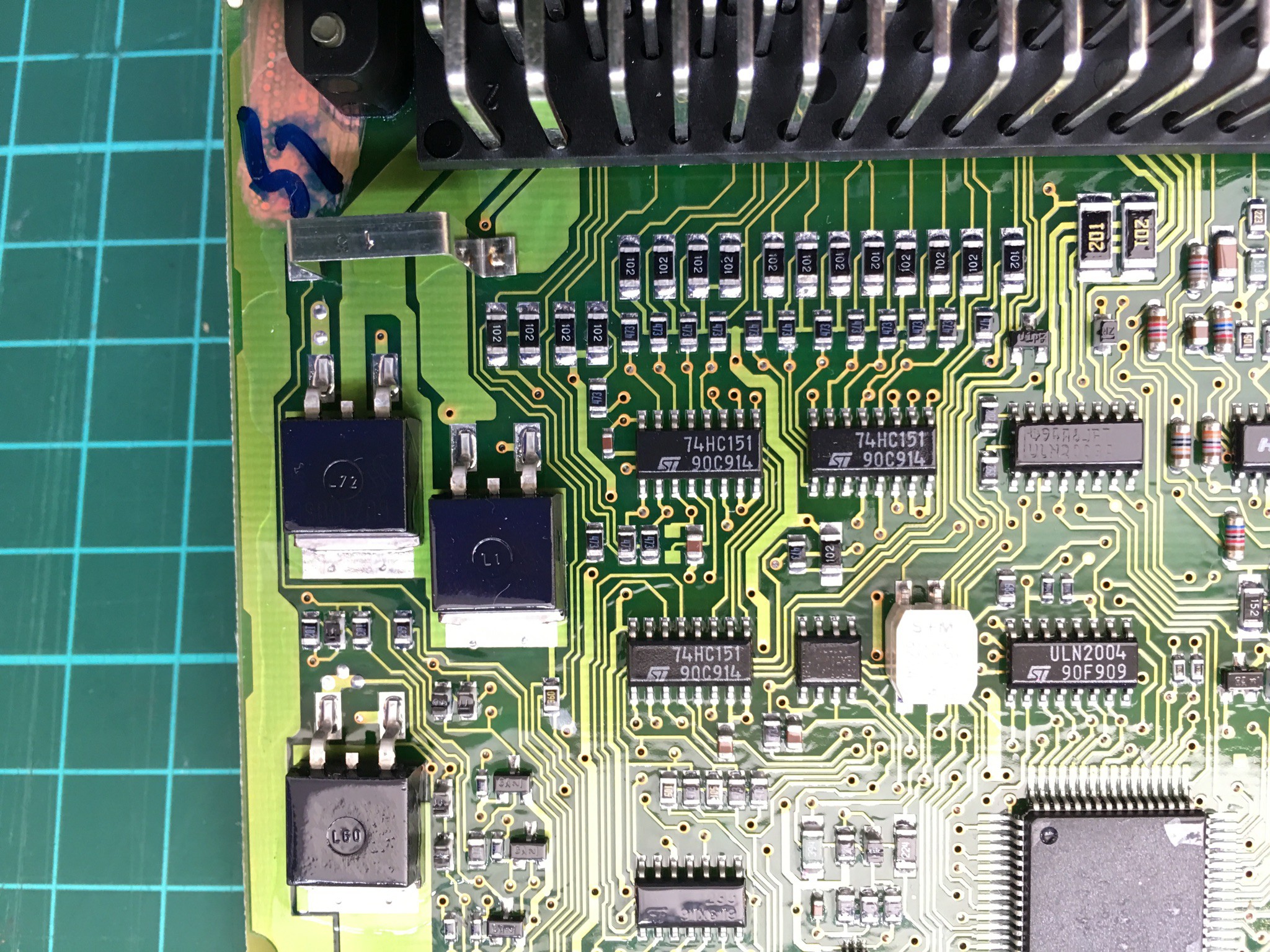
I wanted to do this on my 2005 9-5 and disassembled the instrument panel to access the instrument cluster.

Unfortunately the PCB does not look the same as the pictures of this project.

Anyone who have made 3-blink in a newer 9-5? (2002 - 2005) (or 2006-2010).

I also have a 2001 9-3 coupé and it would be nice to have 3-blink there too but I guess that PCB is more similar to 1999 9-5?

  Are you sure? yes | no

Lars Rune Bjørnevik wrote 06/24/2022 at 10:01 point

I have an updated code file for ItsyBitcy ;)

  Are you sure? yes | no

czabel wrote 04/04/2020 at 04:53 point

While we're all stuck inside, I thought I'd poke you and see if you'd made any progress on those other features you'd mentioned? 

The thing that I'd try to add would be auto up/down windows on long presses. I'm pretty sure the windows are also controlled via the DICE. 

  Are you sure? yes | no

Saabman wrote 04/04/2020 at 06:42 point

I wish LOL, I work in healthcare we are looking at cutting ADOs to keep up with the increasing workload given the current health crisis..

So unfortunately I haven't had a chance to look into any extra features. Though to add the window control from the keyfob may need a fair bit extra work as the window switches at least are disabled when the ignition is off. I suspect the main power for the windows is cut via a relay.

  Are you sure? yes | no

czabel wrote 04/04/2020 at 16:23 point

Ah, fair enough. Thanks for continuing to work, it's appreciated. 

As for the windows, you're talking about what Mercedes do, where if you hold the lock button on the fob, the windows all roll up? That sounds like quite the task. 

Well, if I get to this project, I'll keep ya updated. Stay safe out there! 

  Are you sure? yes | no

Saabman wrote 04/04/2020 at 20:12 point

Ahh your just talking about pressing the normal up down buttons - that would be good. Yeah that should be possible in the same way. Ill try and have a look at that. 

  Are you sure? yes | no

Saabman wrote 04/04/2020 at 20:42 point

I just had a quick look in the WIS (Workshop Information System) the windows are all controlled by a window control module. Its where the switches are in the center console. There is a connection to the DICE but it is only for the switch illumination.

Ill have to pull one apart and have a look.

Id like to implement a system where if the windows are open and you lock the door it automatically winds the window up leaving it open about 5 cm. From what I can glean from the WIS it appears the switches themselves carry the full current of the window motors so it will take a fair addition to the module to make it work. Maybe when all the COVID stuff has settled my boss will let me have a some of (LOL)

  Are you sure? yes | no

czabel wrote 04/06/2020 at 06:03 point

Wow, yeah you're right - it's surprisingly complicated inside the window switch pack! I just emailed ALPS to see if they'd be willing to share the schematic for a long-dead car part... Fingers crossed I suppose. 

If that's the case that everything goes through the switches, a relay or two would need to be added. Not impossible, but maybe not quite the slam dunk that the blinkers were. 

  Are you sure? yes | no

Saabman wrote 04/06/2020 at 12:13 point

to save mudling up the blinker project ive created a new project for the windows https://hackaday.io/project/170784-saab-9-5-window-control-module-modifications

  Are you sure? yes | no

Saabman wrote 02/06/2021 at 04:41 point

I had a bit of a look at the window system and it is totally controlled by the switches so to get it interface from the key fob would entail a fair bit of work - intercept the lock/unlock signal and then build drivers (could just use relays) . Its not impossible just a fair way down my priority list at  this stage. All my SAABs are currently unregistered and parked up as well so no chance of it rising up in priority in the near future.


Bluetooth in my Chrysler is my priority project at the moment...

  Are you sure? yes | no

czabel wrote 07/15/2019 at 16:54 point

Nice work! I just got a 9-5 and miss this feature from my previous car. Now that you've been using it for a while, have any issues shown up? Any improvements to report? I'm ordering a Pro Micro now to do this mod either way... 

  Are you sure? yes | no

Saabman wrote 04/04/2020 at 06:48 point

Awesome - I absolutely love my 9-5. Its a bit worn around the edges  and isnt the greatest color but its just a pleasure to drive.
The operation of the module has been great the only thing I would think of altering is the length of time. Its currently 3 blinks but that is a bit short in Australia it should be 3 seconds which is probably about 5 blinks.

  Are you sure? yes | no

Jeff Verive wrote 08/11/2018 at 22:44 point

Nice work! BTW - you probably don’t need debouncing if you mask off the interrupt in the beginning of the interrupt service routine and then unmask it after the blinking is complete. 

  Are you sure? yes | no

Saabman wrote 08/12/2018 at 03:17 point

I would like to do some more work with interrupts to learn more about them and effective implementation so I might rewrite the firmware and have another go using intterups and try masking as you’ve suggested and see if I can make that work - though by not using interrupts it can be built by a greater variety of boards 

  Are you sure? yes | no

Max wrote 08/11/2018 at 19:43 point

Very nice!

  Are you sure? yes | no

Saabman wrote 05/30/2018 at 00:38 point

thanks guys.

As all the controlled is handled by the DICE module there’s no separate blinker relay as such. So needed an internal solution and I’ve implemented it in such a way that there is no modification to the wireing harness and it can be removed easily and normal function restored. 

I’ve got a few other things I want to implement - like auto up windows when the doors are locked. 

I’ll check that group chat.

Bernie

  Are you sure? yes | no

AVR wrote 05/29/2018 at 17:37 point

very cool!! I'm assuming that one of those programmable relays was not available for your car so you rolled your own solution, very nice!!!! I did an LED conversion mod for my signals but just bought a special relay to handle it. 

If you want to chat about car modding and car anything I made a group chat that needs more car hackers and enthusiasts. 

https://hackaday.io/project/157813-automotive-enthusiast-chat

We'd be happy to have you!

  Are you sure? yes | no

Mike Szczys wrote 05/29/2018 at 17:34 point

This is incredibly awesome. You're backporting features on your car! Nice.

  Are you sure? yes | no

Similar Projects

Does this project spark your interest?

Become a member to follow this project and never miss any updates