0%
0%
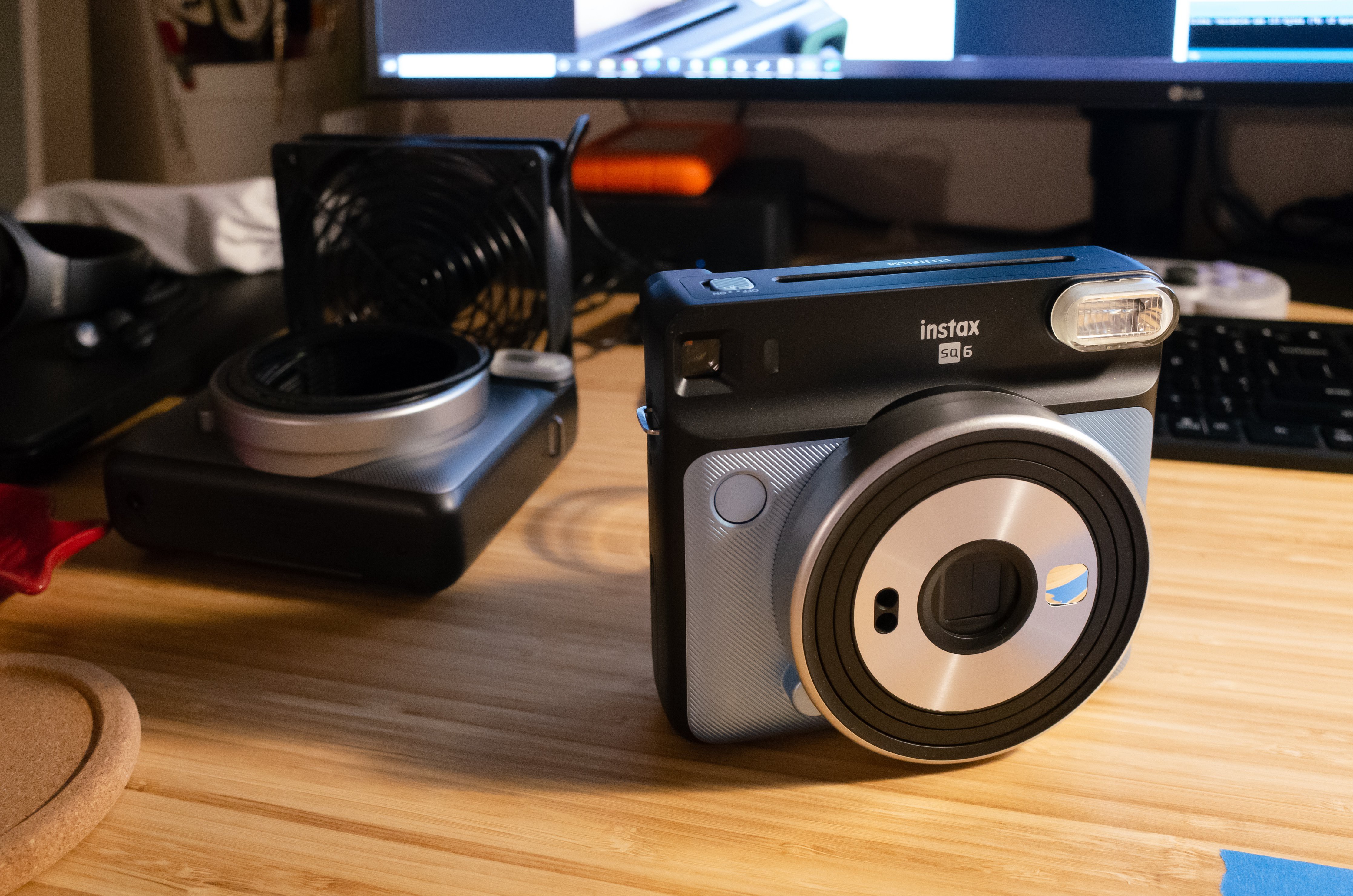
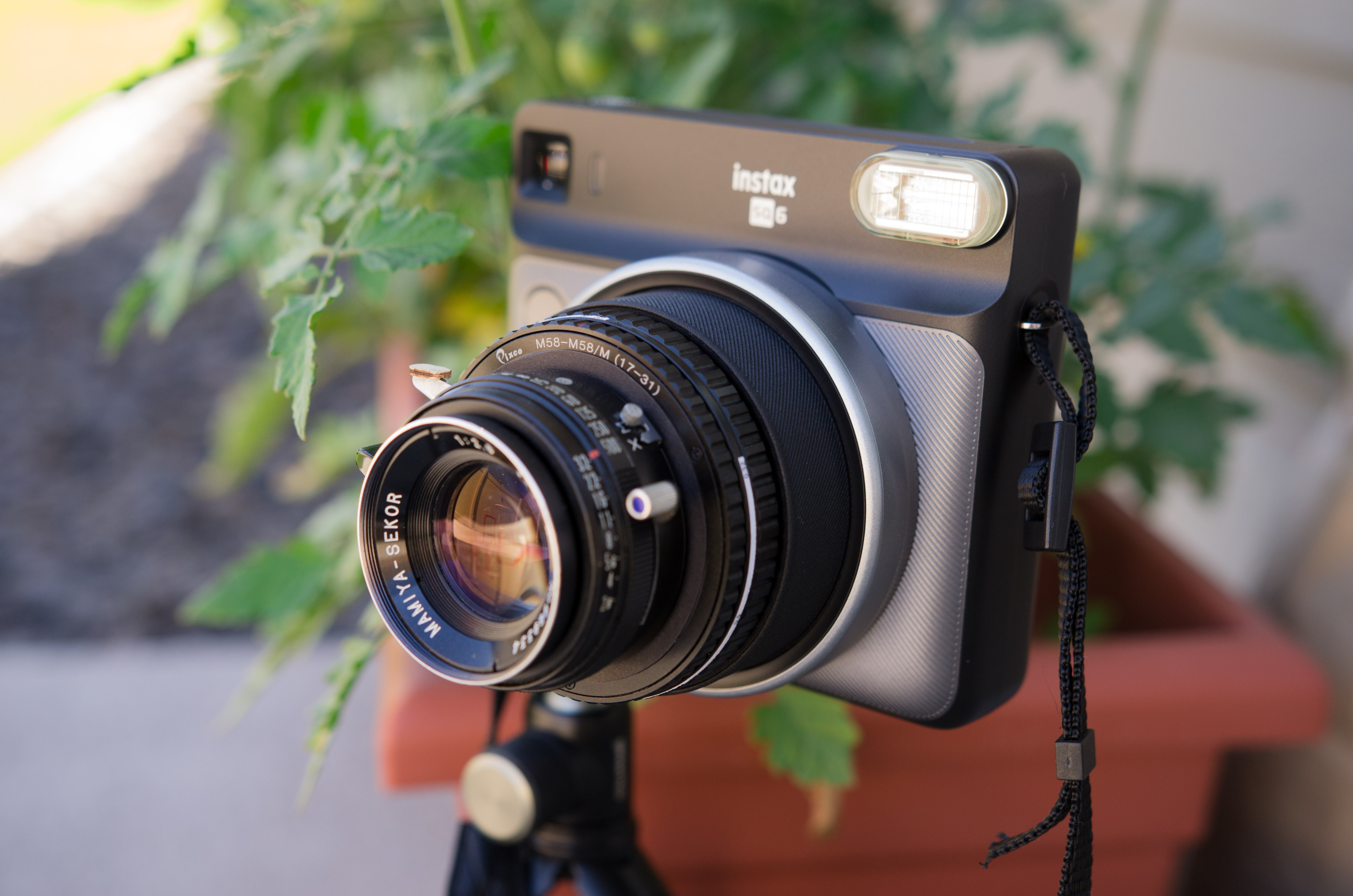
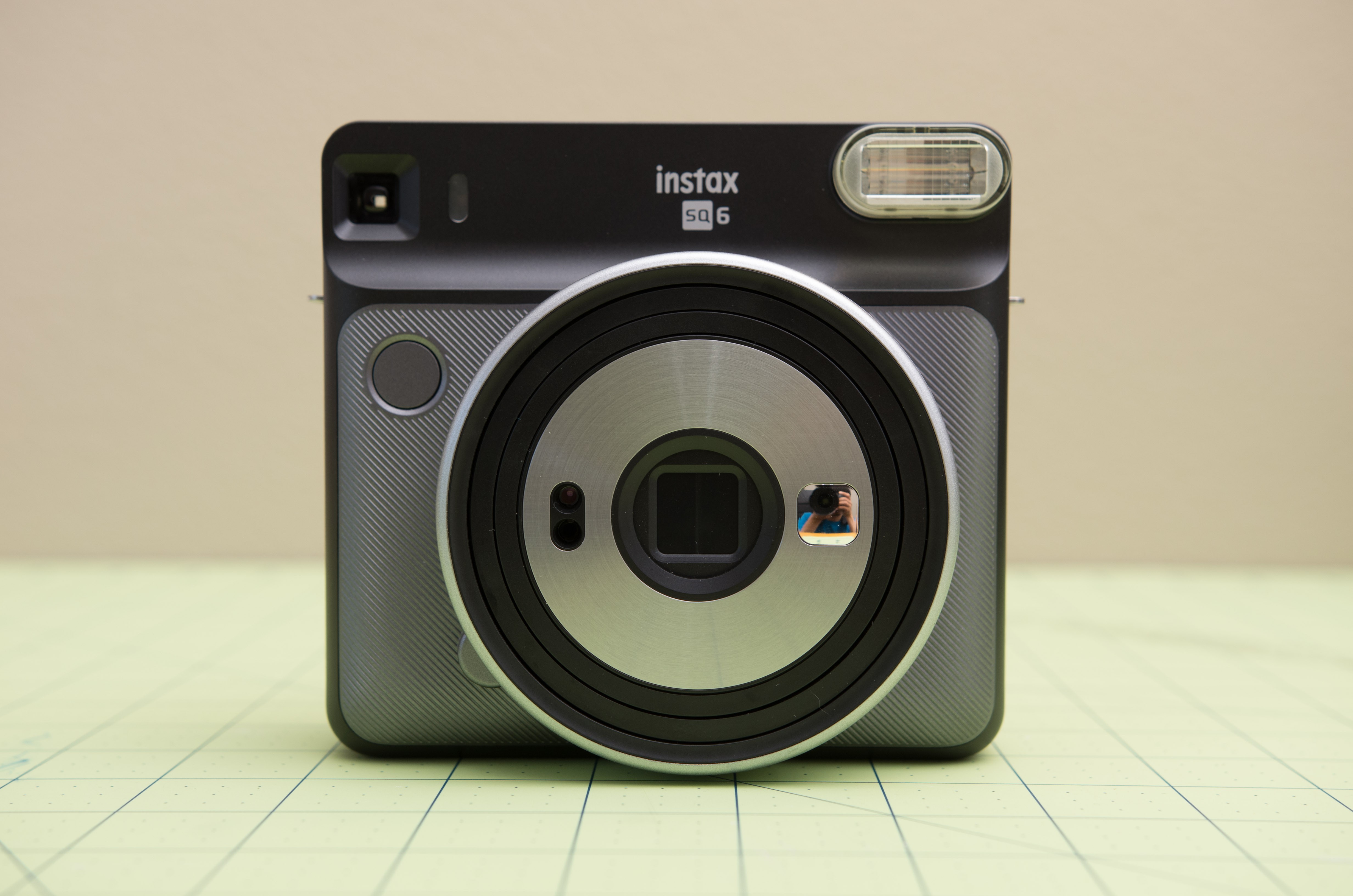
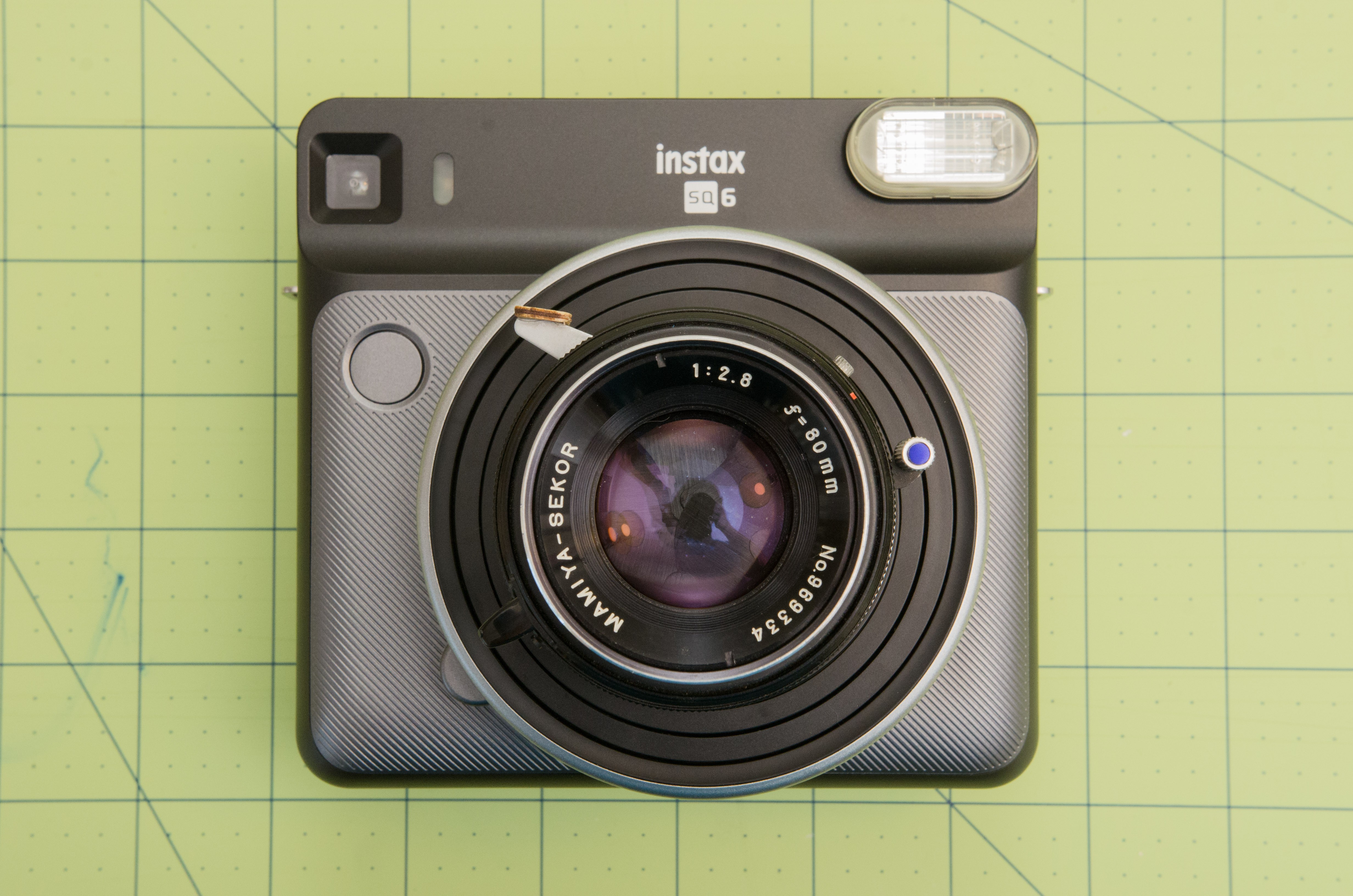
Instax SQ6 Lens Transplant
Adding a "real" lens to Fujifilm's first (and only) analog square format instant camera.
 Kevin Kadooka
Become a Hackaday.io member
Already have an account? Log in.
Just one more thing
To make the experience fit your profile, pick a username and tell us what interests you.
Pick an awesome username
hackaday.io/
Your profile's URL: hackaday.io/username. Max 25 alphanumeric characters.
Pick a few interests
Projects that share your interests
People that share your interests

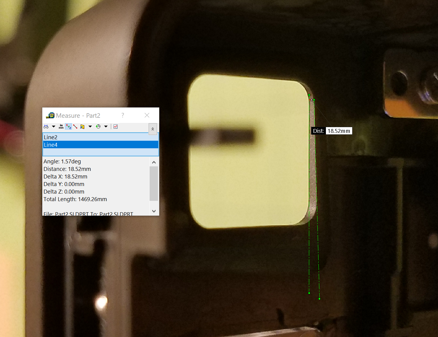 For some object at a distance b, we can calculate the error da in positioning of the viewfinder center:
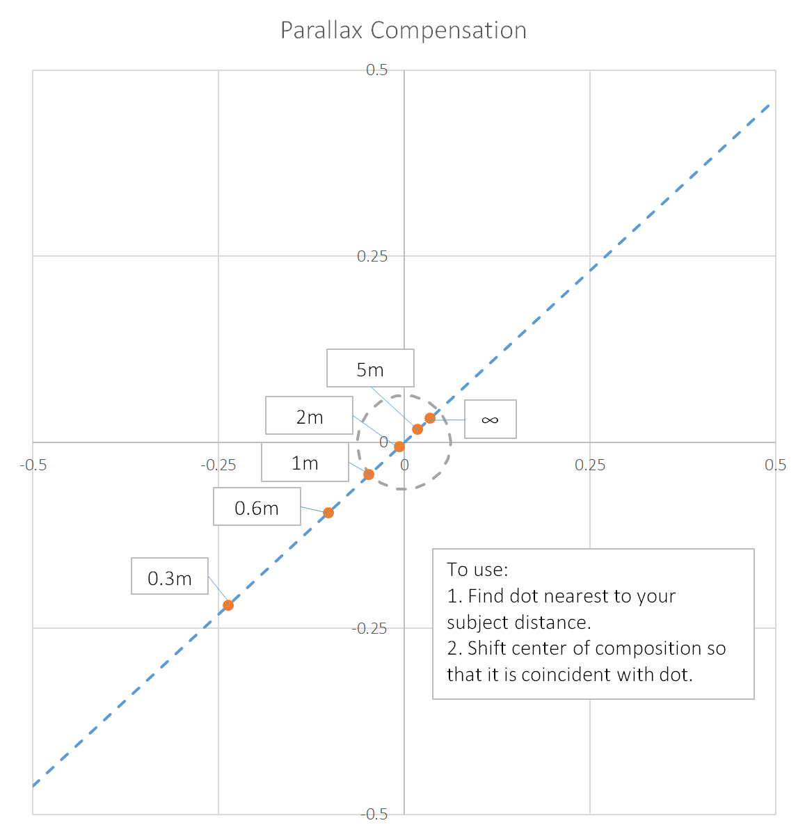

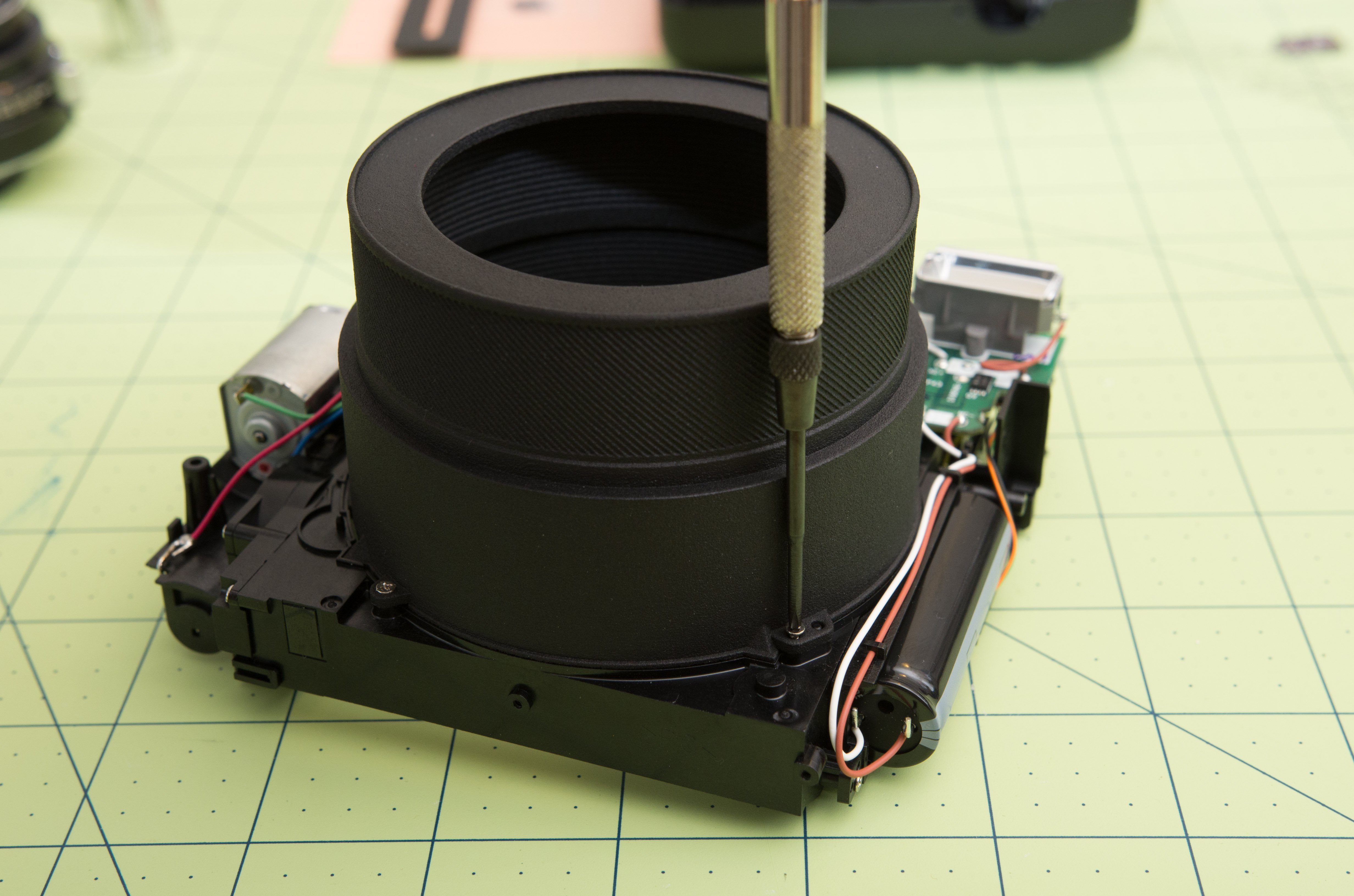
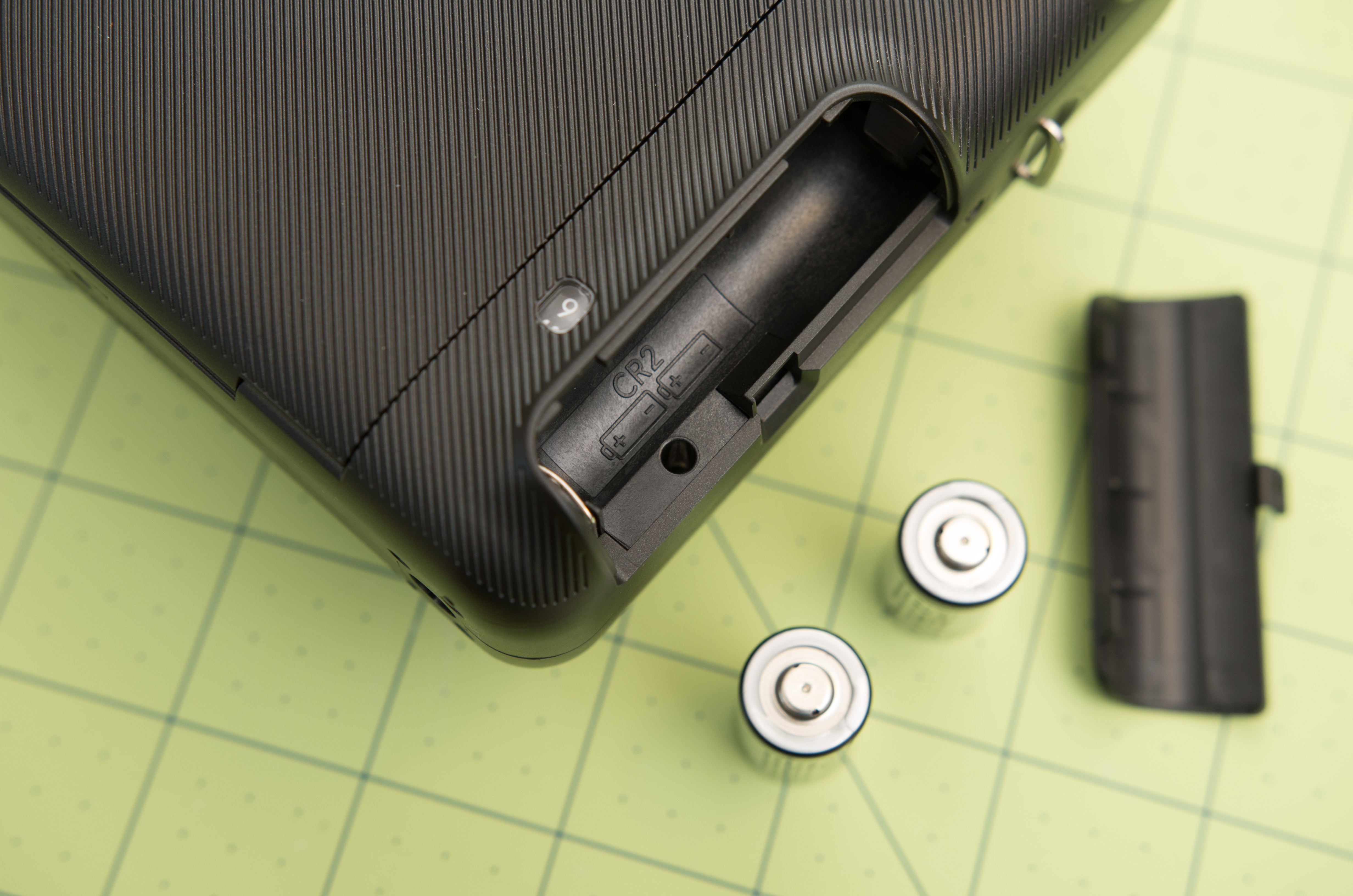
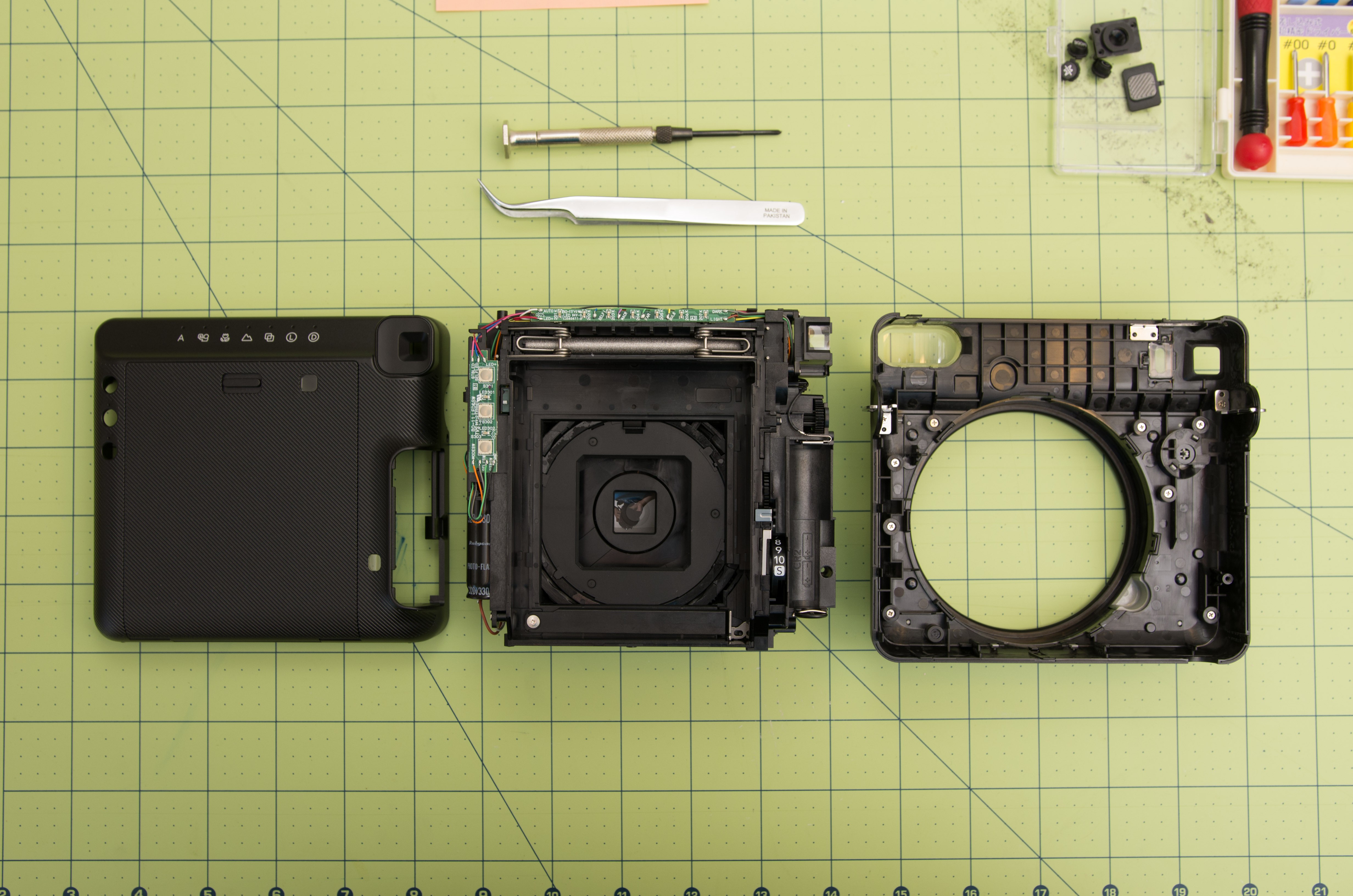
 Five more screws on the bottom of the camera:
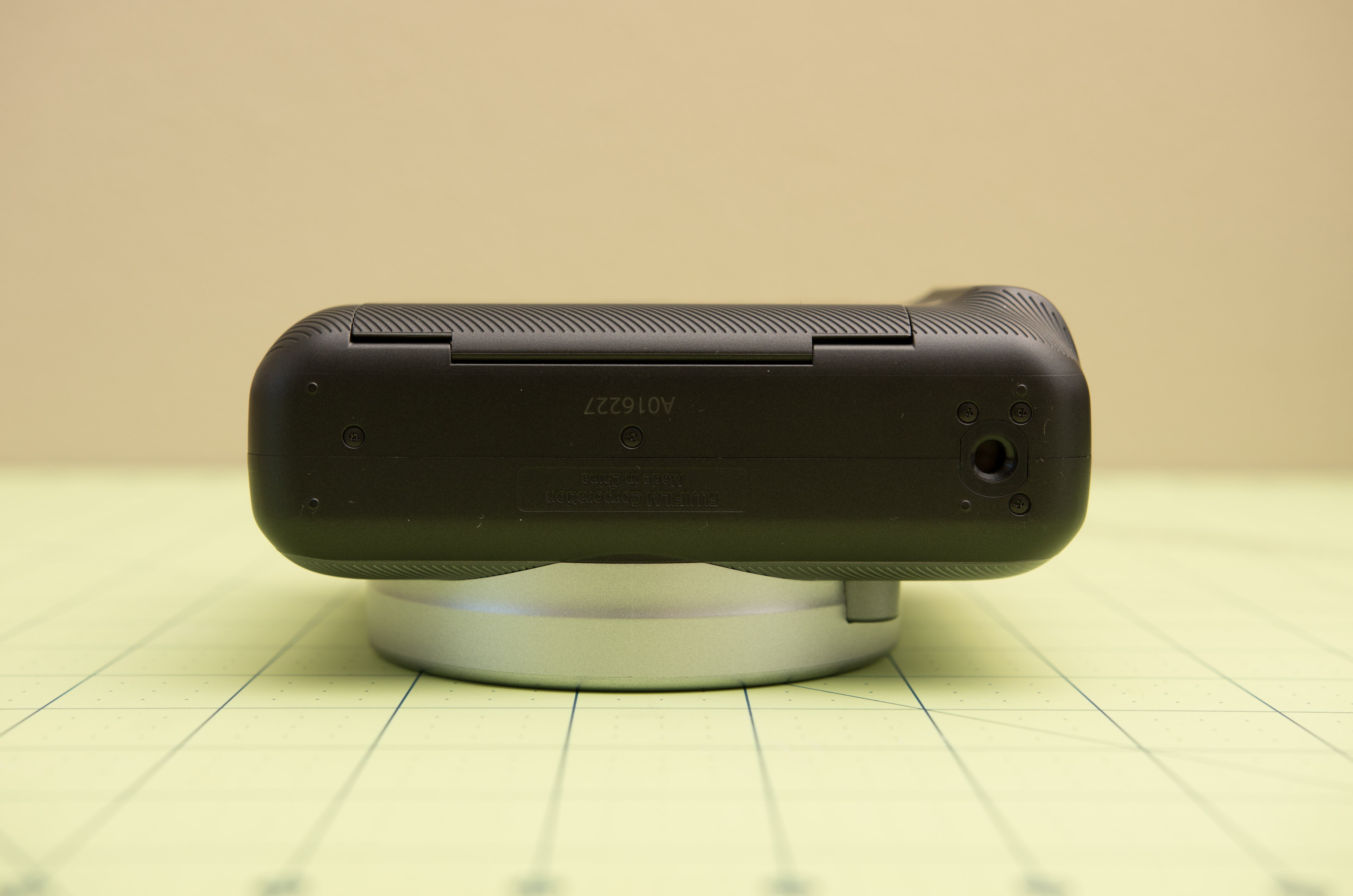


 Quinn
Quinn
 Chris
Chris
Hi, I've just followed up this project. It's really amazing. Thanks for sharing all the process and design files to us.
I still have a couple of questions.
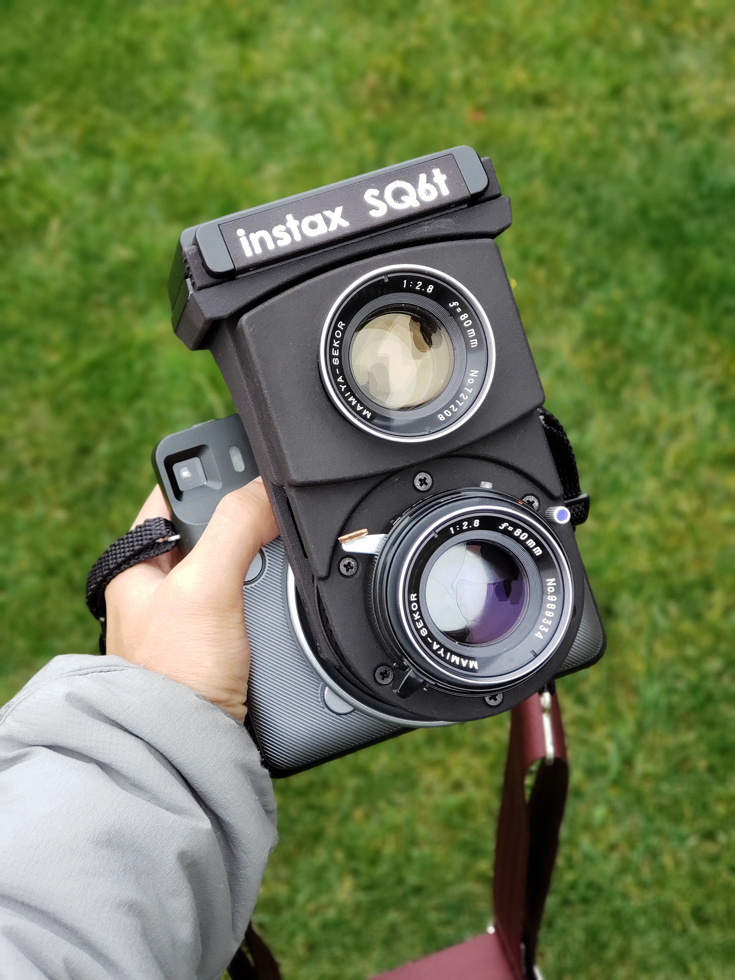
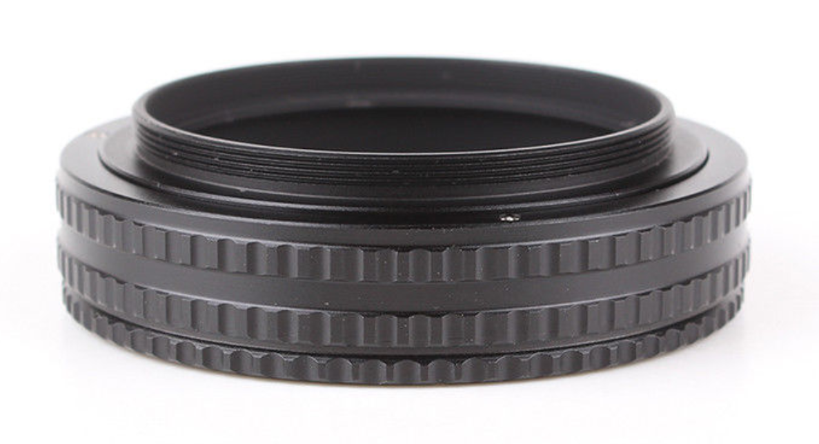
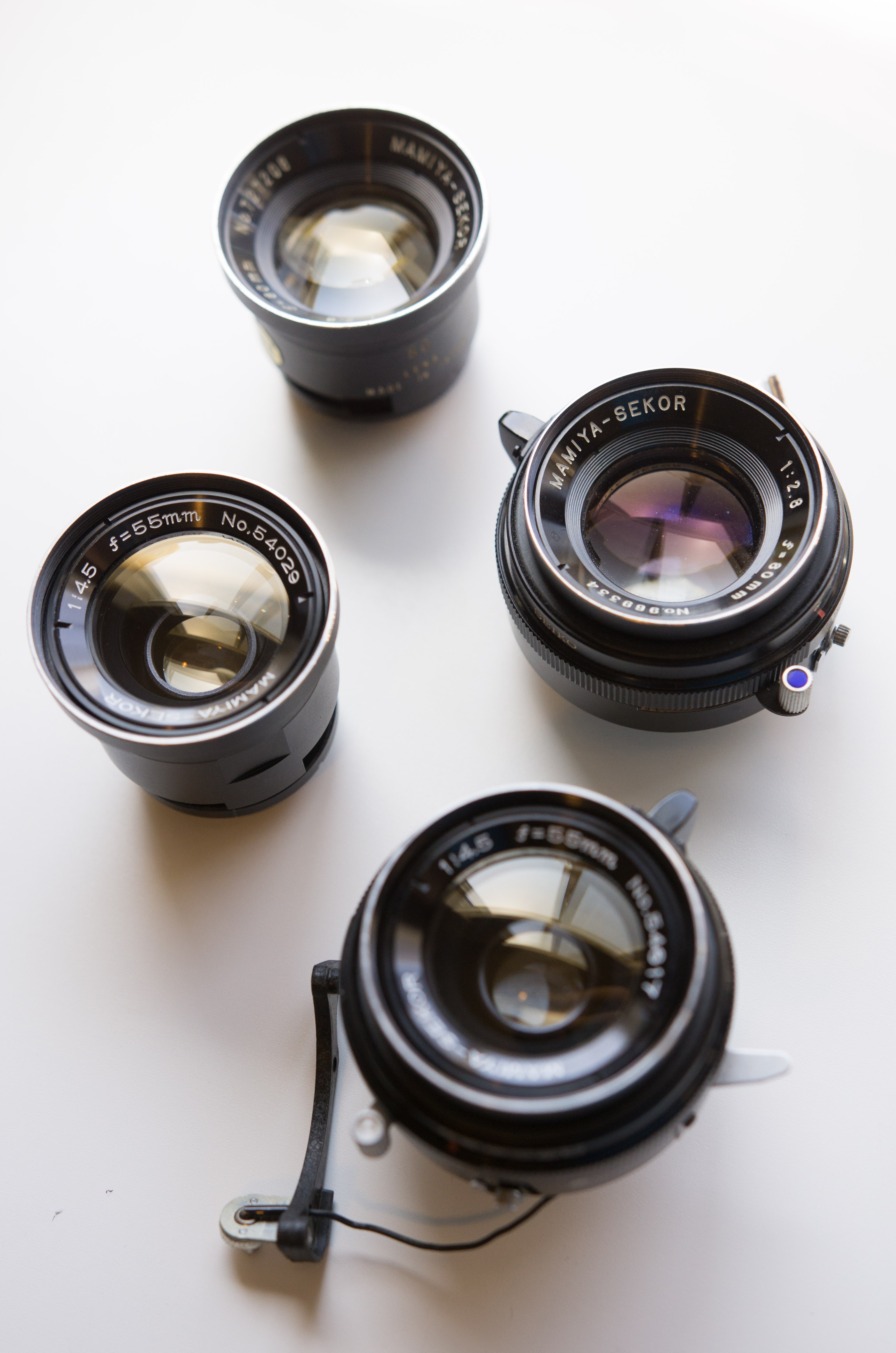
1. Could other Mamiya TLR lens (such as 55/4.5 & 65/3.5) work on this camera?
2. Since the two lens (photo lens and viewing lens) are separated, there would be an effort to tune the focusing system, which make both of the lens focus on the same plane, right?
Thanks again for sharing generously!