 Kevin Kadooka
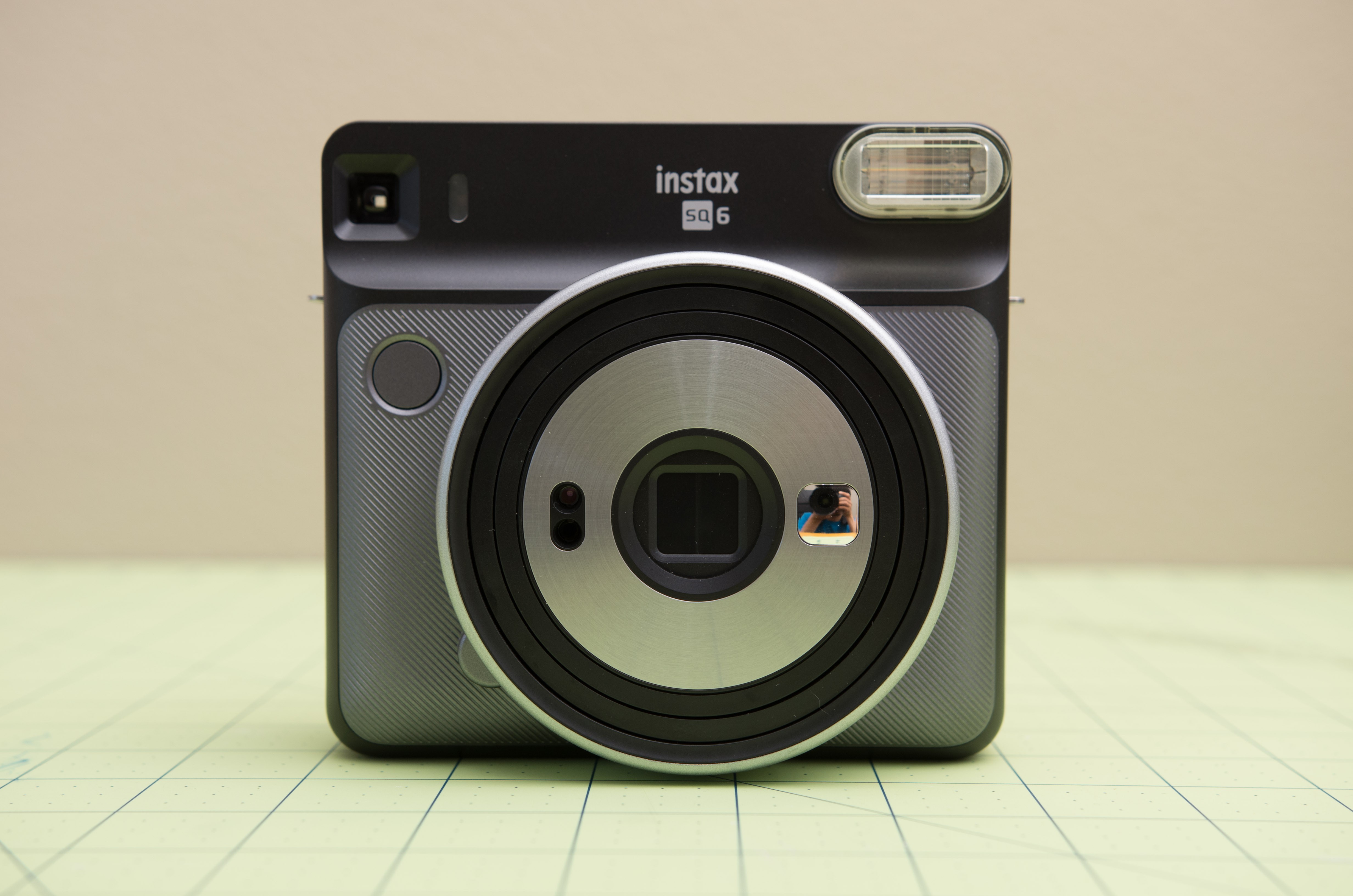
Take this:
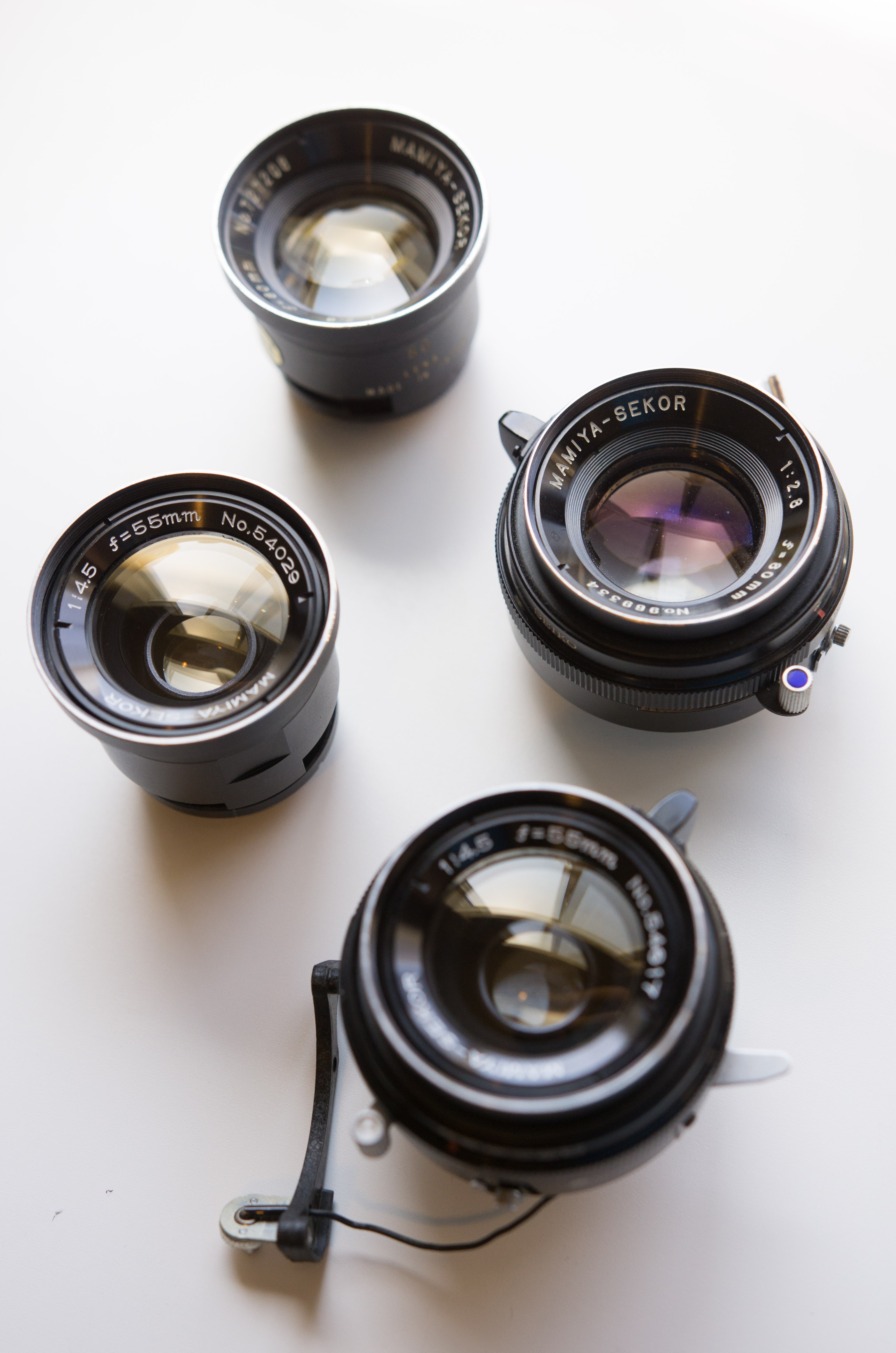
And add one of these:
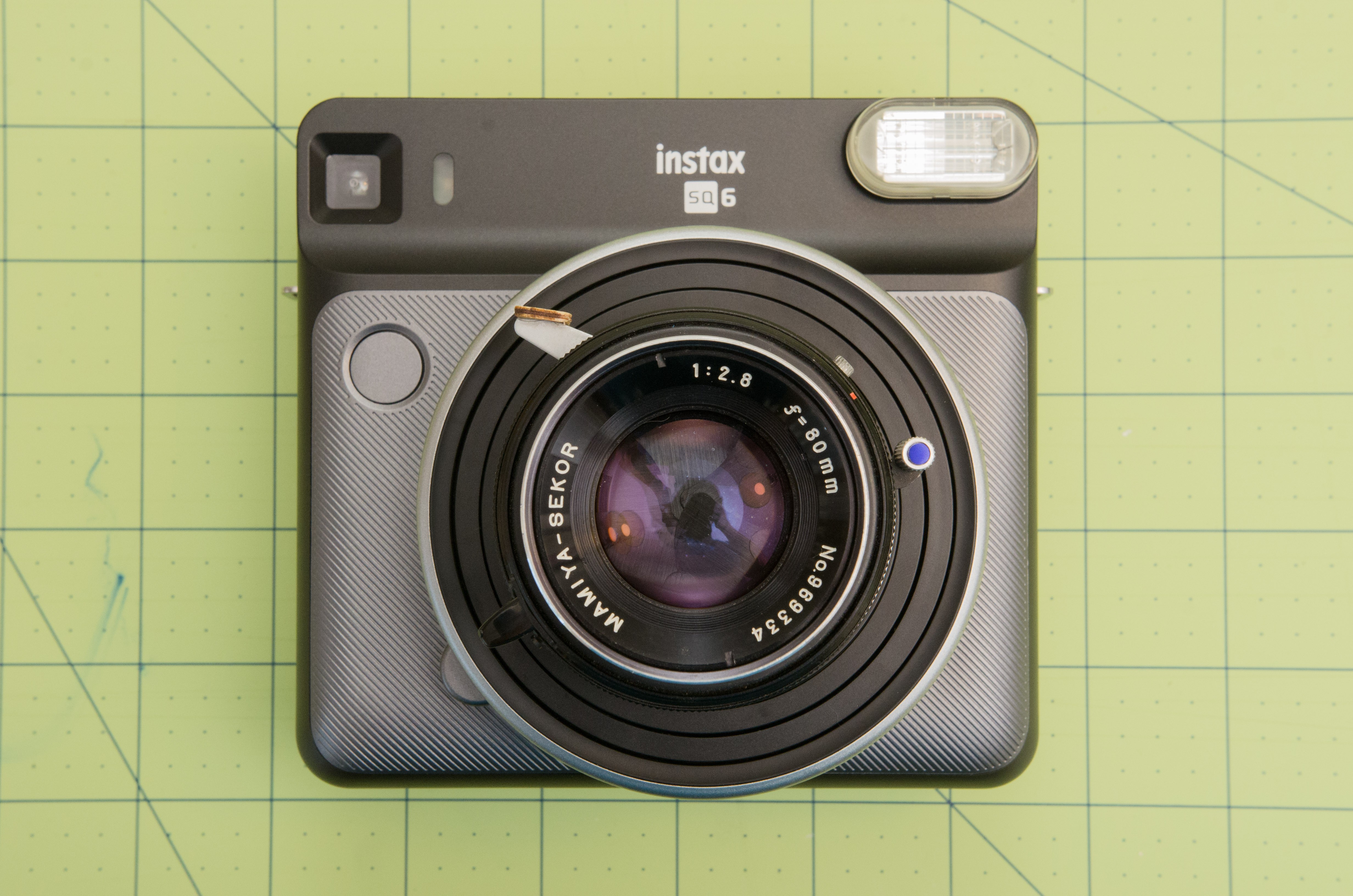
To form this:
The SQ6 is a fun camera, but I think it lacks the image quality that it would make it great. The two-element 65mm f/12 lens is pretty limiting; the images aren't as sharp as the Instax film can resolve, and the defocused areas look hazy and smudged instead of smooth. The lack of manual controls can be frustrating; exposure controls are automatic only, and even with the relatively small aperture and three focus zones, parts of images are often out of focus.
I already have a couple of Mamiya TLR lenses from other projects, and I thought they'd be a natural fit for this project. The 80mm f/2.8, in particular, seems like a good choice. Previous use of this lens on FP-100C (RIP) shows that the image circle is quite a bit larger than the 56 x 56mm frame it was designed for:

The bottom line is, the 80mm lens will cover the 62 x 62mm Instax Square film nicely, be 4 stops faster, and offer manual exposure control. Upon making this realization - scarcely 48 hours after buying the camera - I pulled it apart to see how I might complete this lens transplant.
The first step is to remove all of the exterior screws. Typical for a Japanese camera, the screws are not Philips-type - they are JIS (Japanese Industrial Standard). Using an appropriately sized Philips head screwdriver won't hurt anything, but the job is made easier with the right tools. Moody Tools makes a nice and affordable set of JIS screwdrivers, which I highly recommend for this type of work.
Before I delve into things, please remember that high voltage is present inside the camera, so conduct your disassembly accordingly. Even with the batteries removed for an hour or two, charge is held in the flash circuitry and will give you an unpleasant shock if you unwittingly touch the wrong terminals. You have been warned.
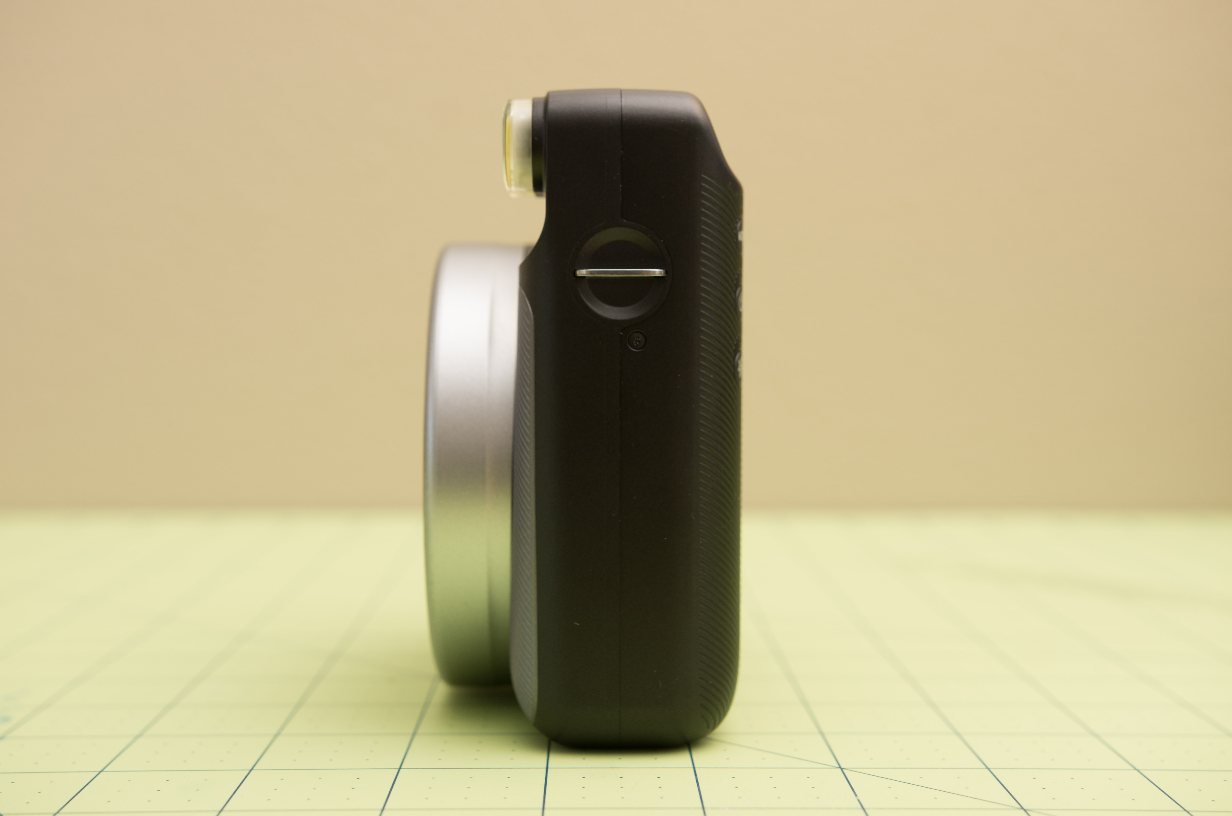
There's one screw on the viewfinder side:
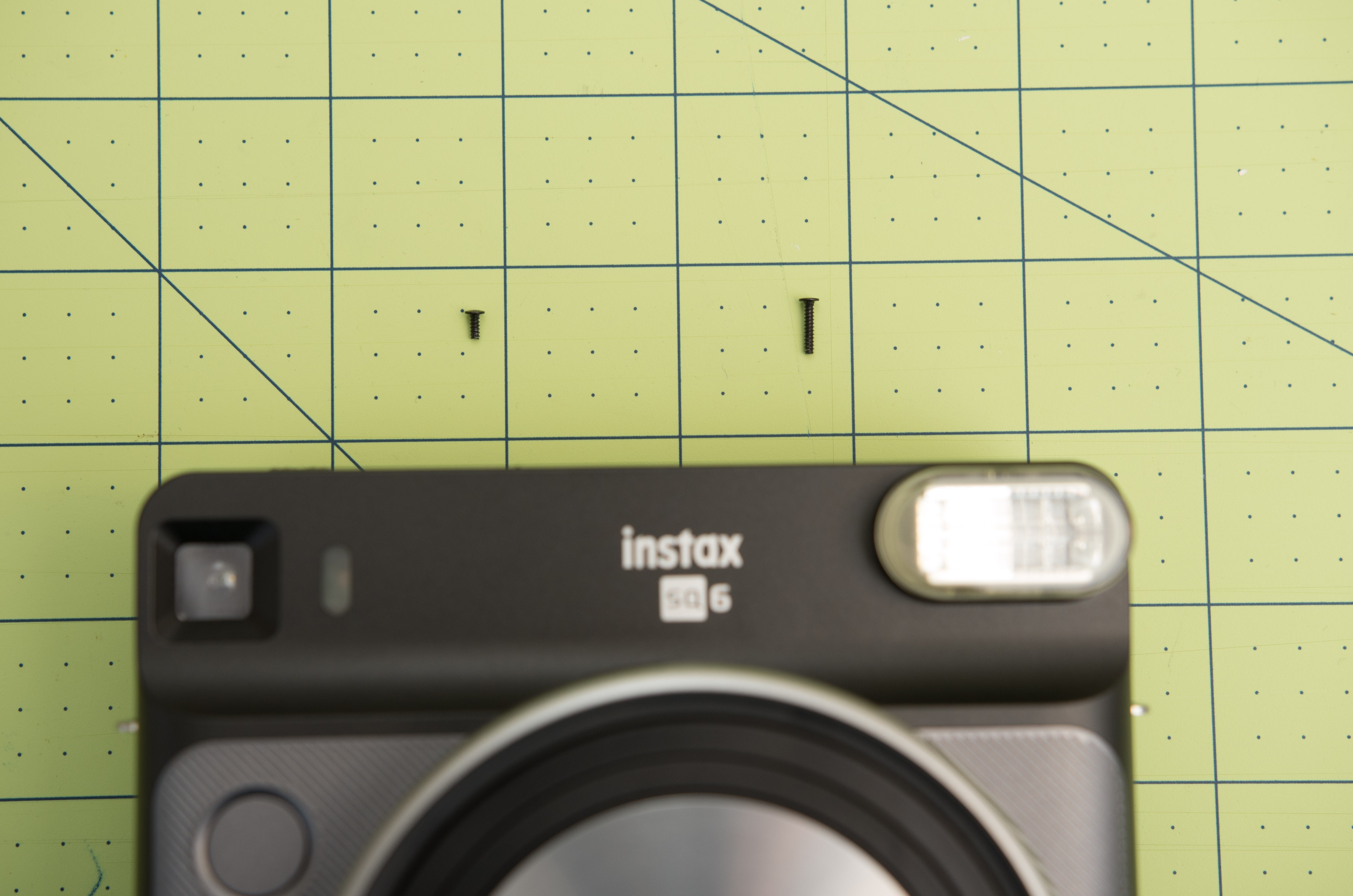
One more screw on the flash side:
Note that the screw on the flash side is longer than the viewfinder side. Keep that in mind for reassembly.
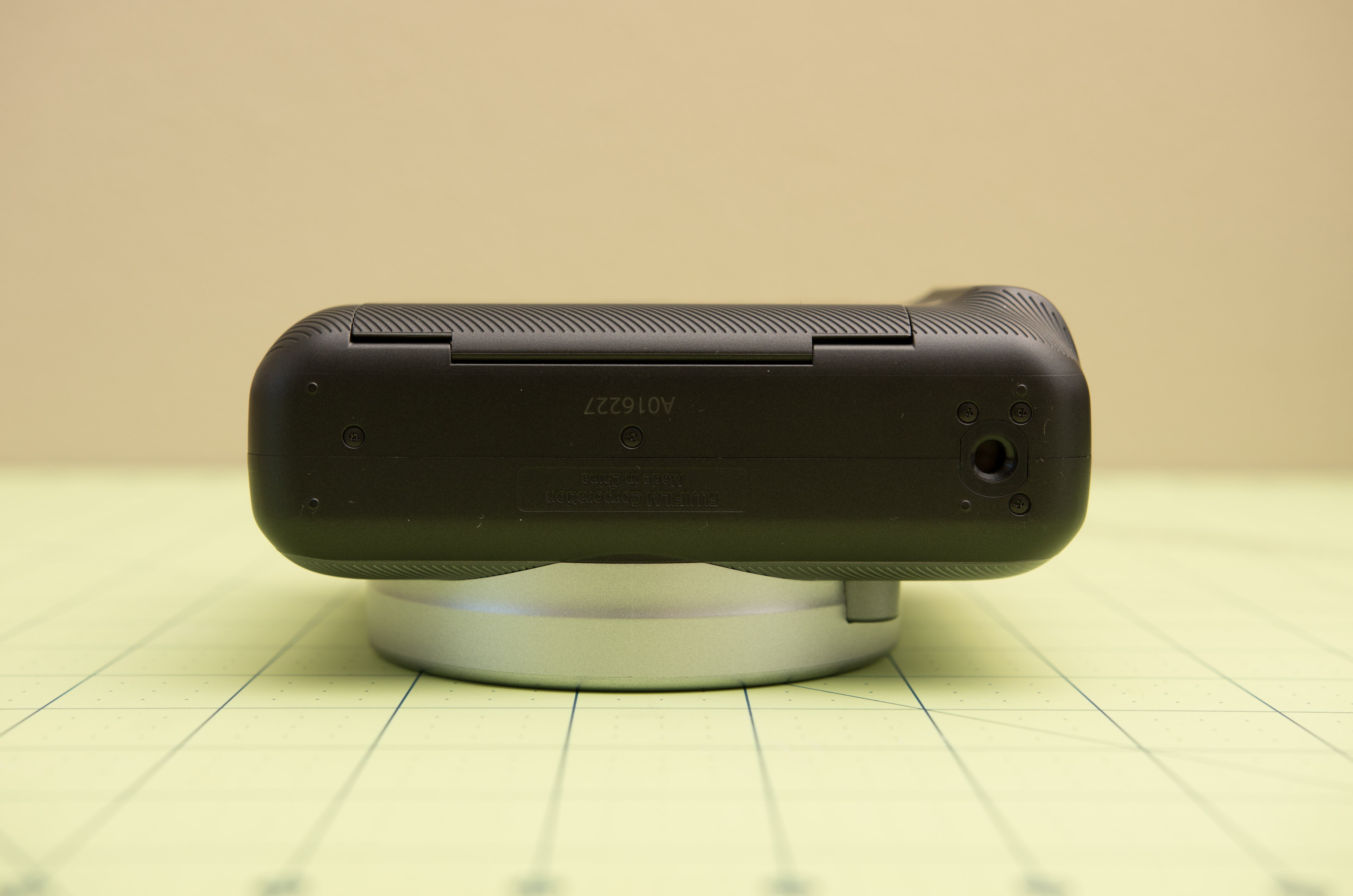
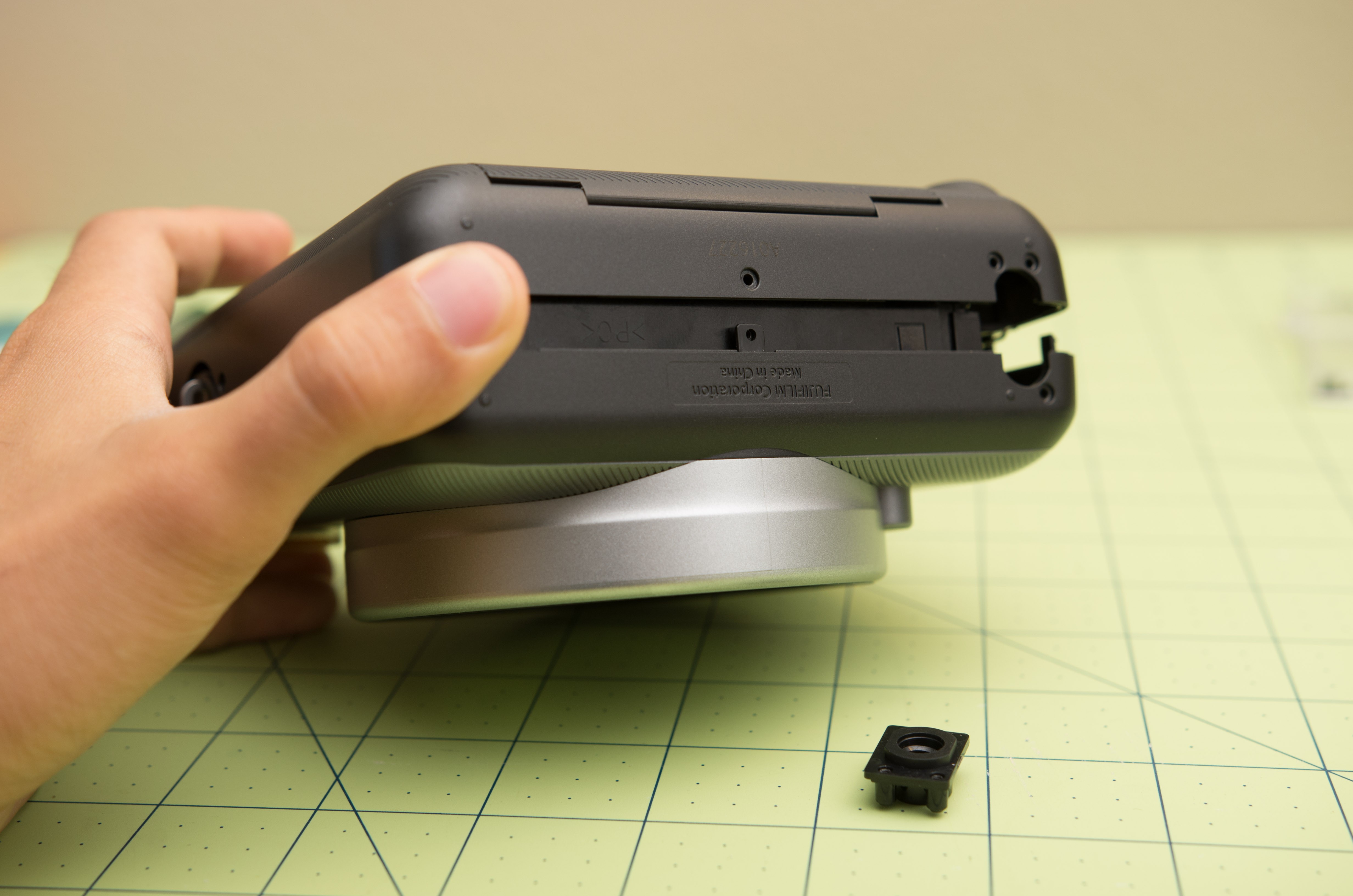
 Five more screws on the bottom of the camera:
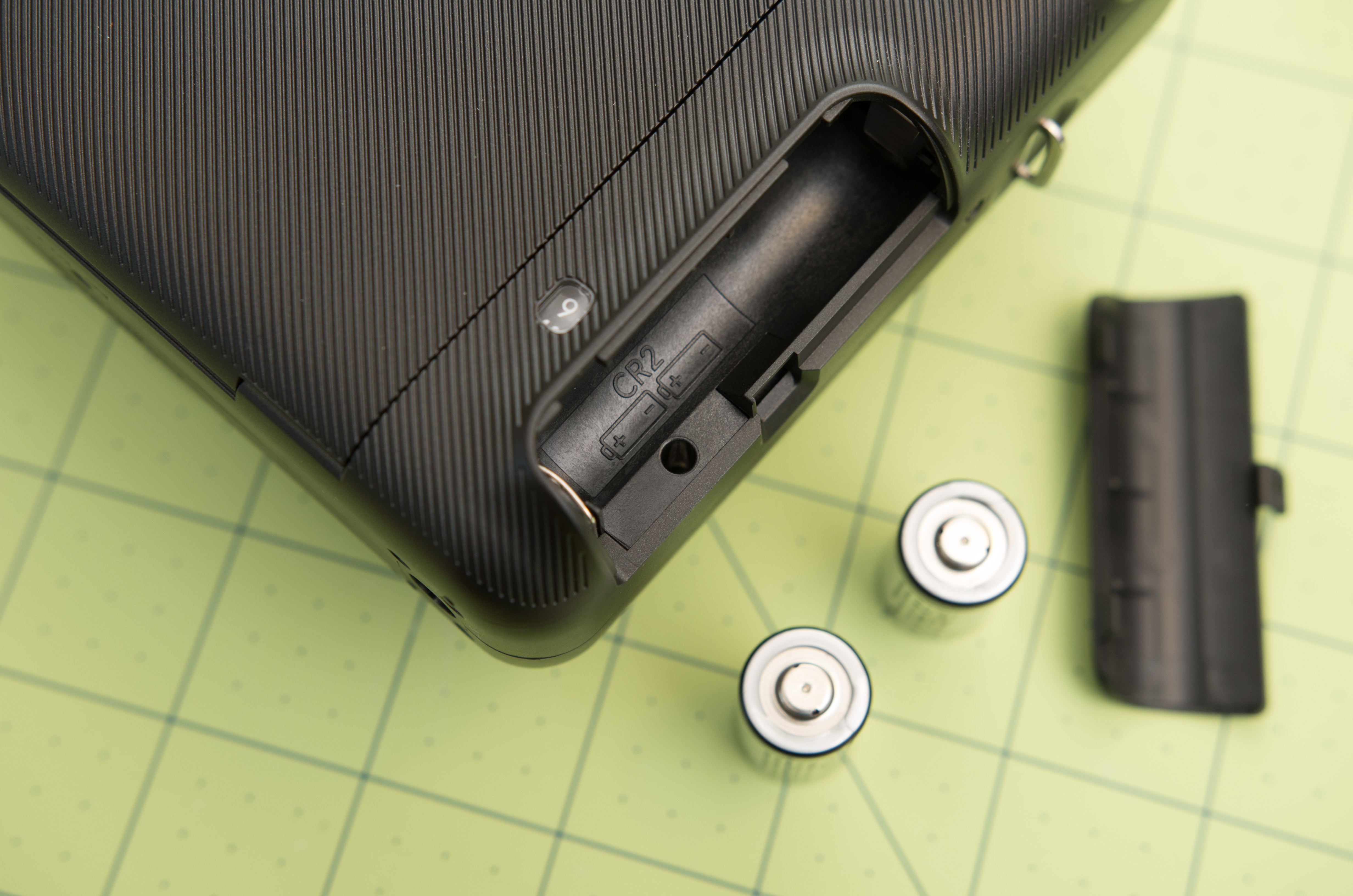
One screw in the camera compartment:
Now, you should be able to wiggle the two halves of the camera shell apart. Right now, the top will not separate because there are still some screws to remove. At this point, the tripod mount will probably fall out, make sure you save this.
The halves are kept together with a myriad of tiny clips:
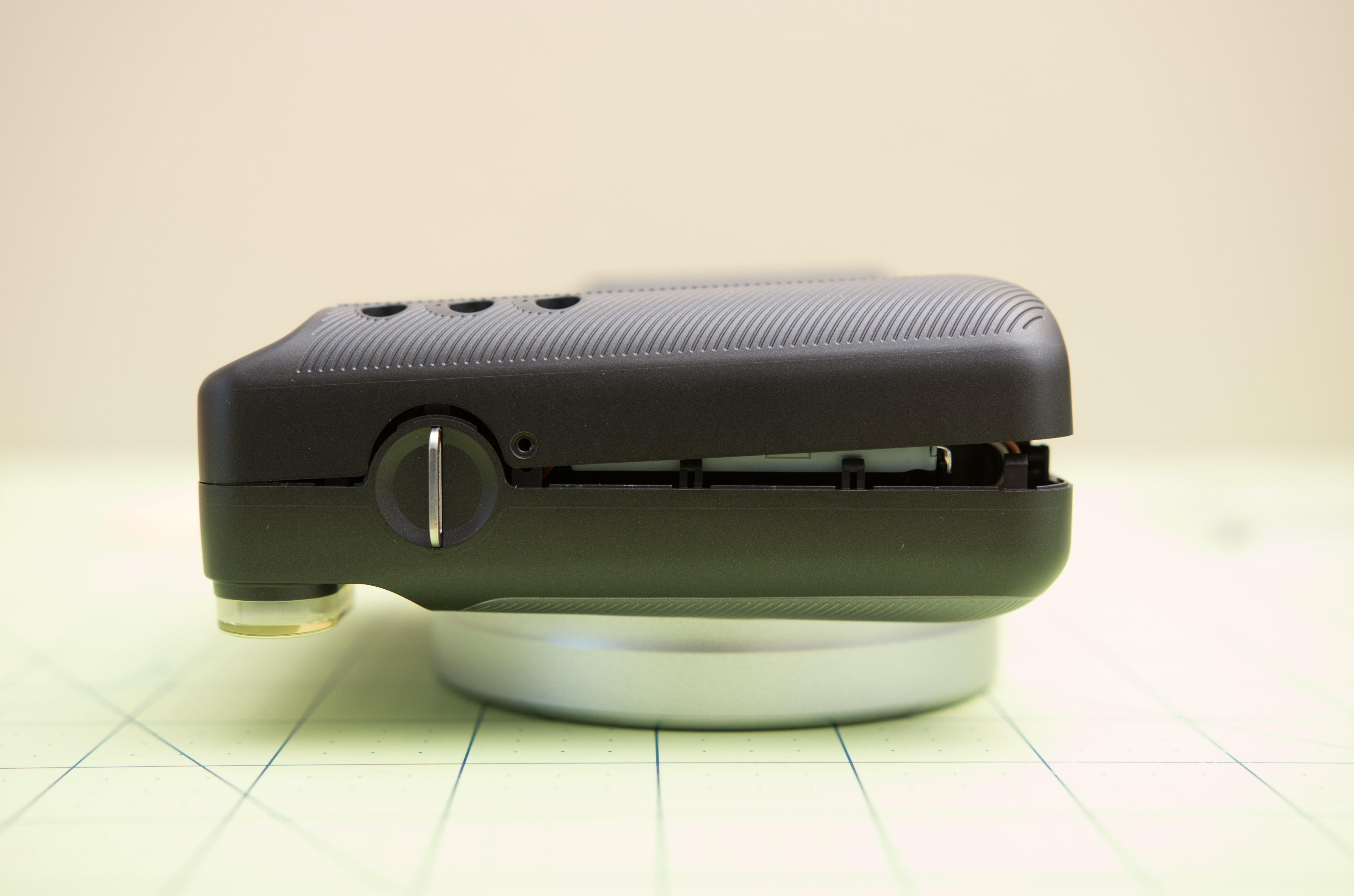
The top fascia must be removed. You could do this with a plastic spudger, or as I have done, a thin strip of metal.

The top fascia is held on with a combination of clips and double-sided tape. Keep peeling away at it until it pops off. The power switch will also probably fall out somewhere in this process, keep that one safe too. From here you can see the two screws on top of the camera which must be removed.

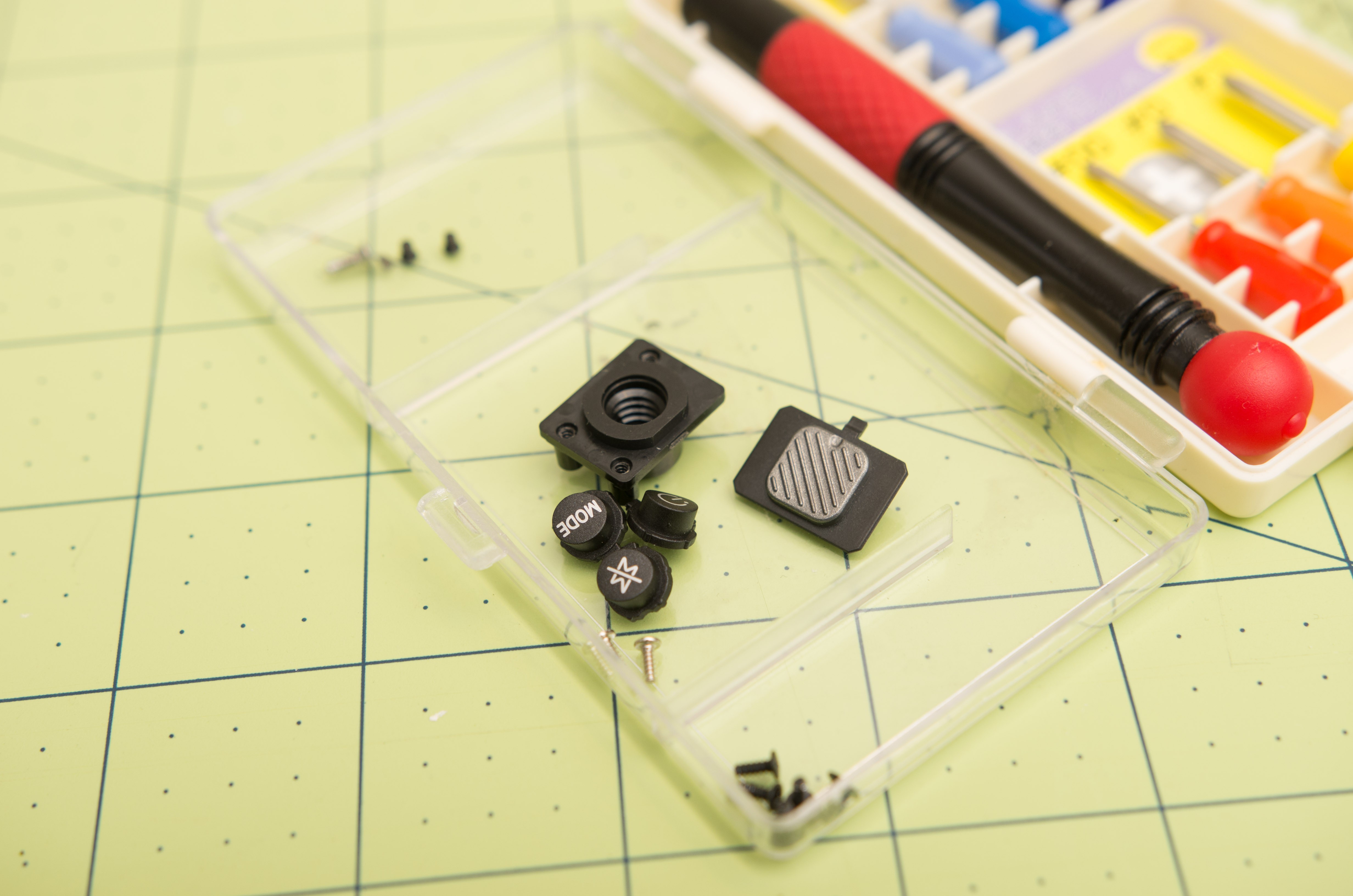
By now, you probably have an assortment of orphaned parts: the power switch, tripod mount, and 3 control buttons.
With the last of the screws removed, the two halves of the camera can be separated:
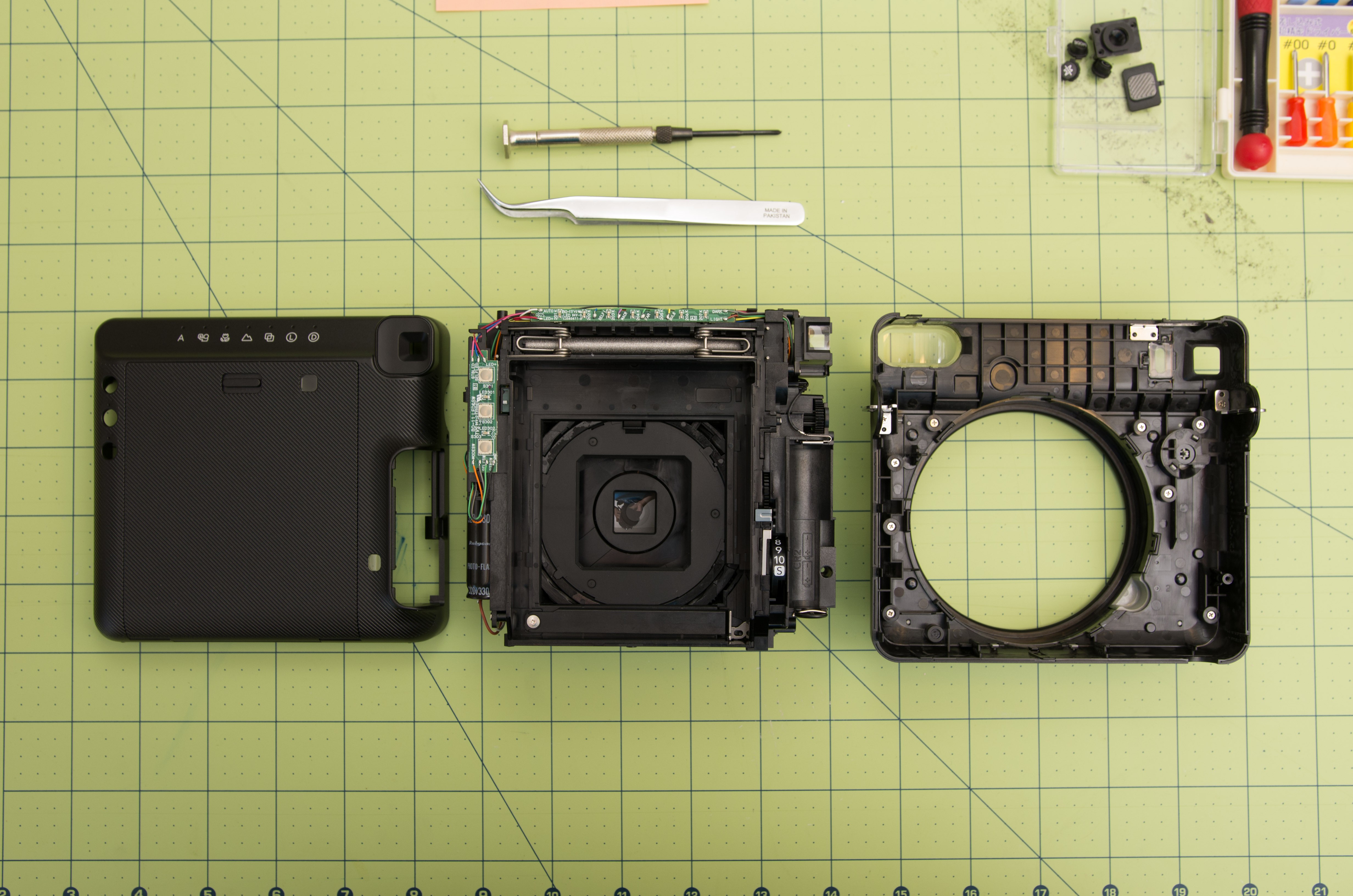
A thin plastic ring will fall out when you separate the front shell and the main camera unit. I think this is a light sealing gasket.
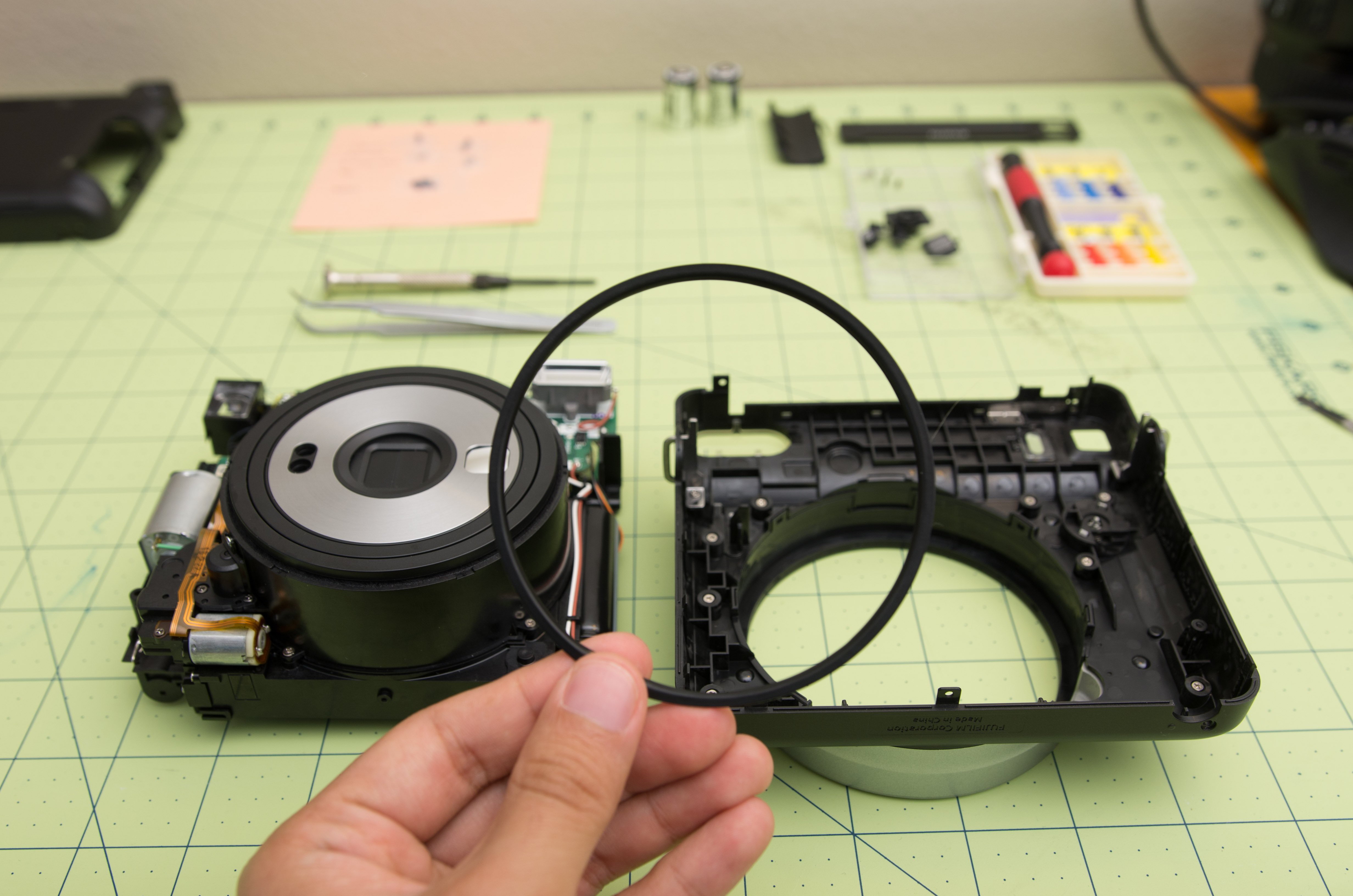
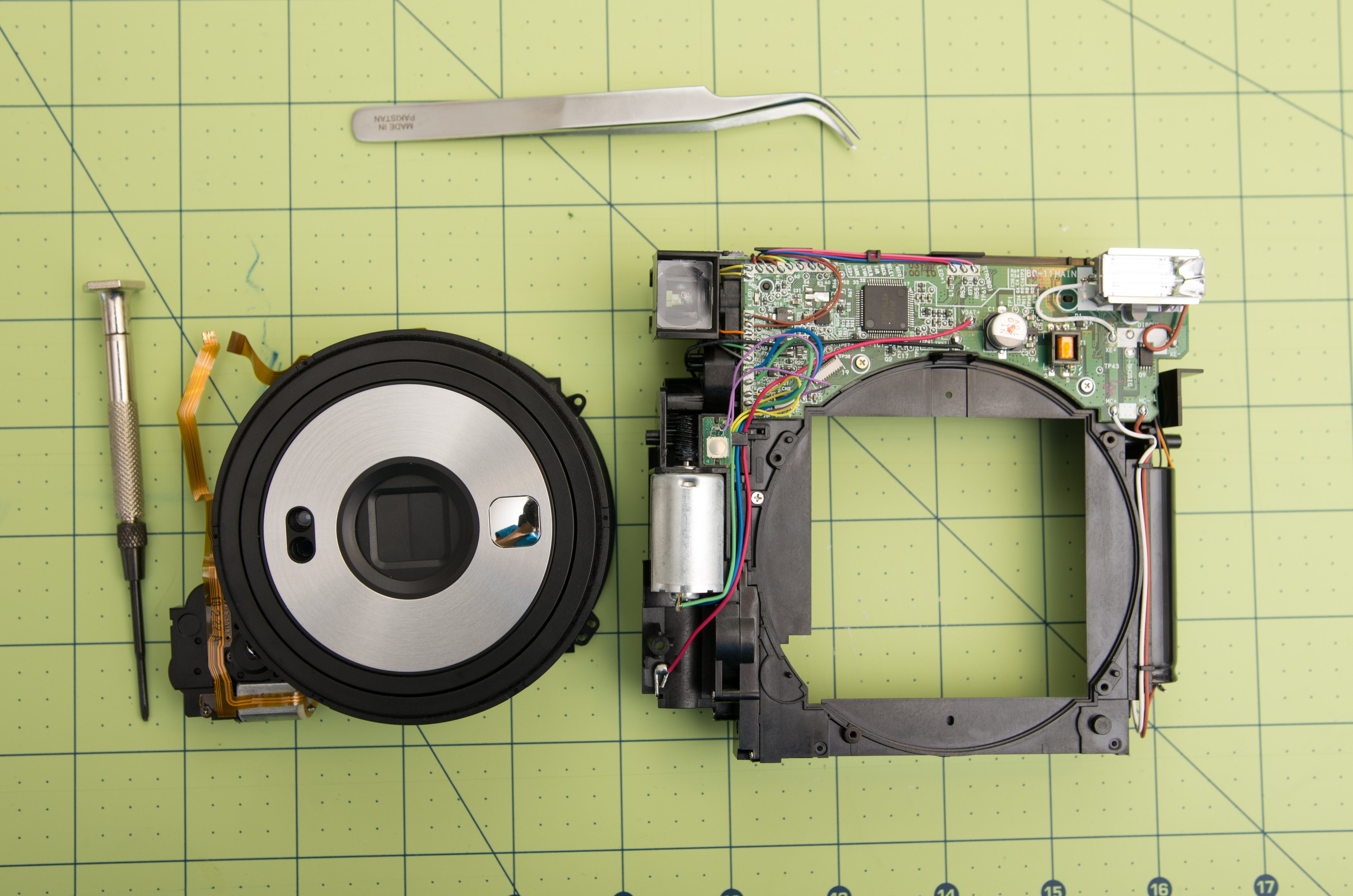
Here's what the main camera unit looks like, from the front:

...and the back:

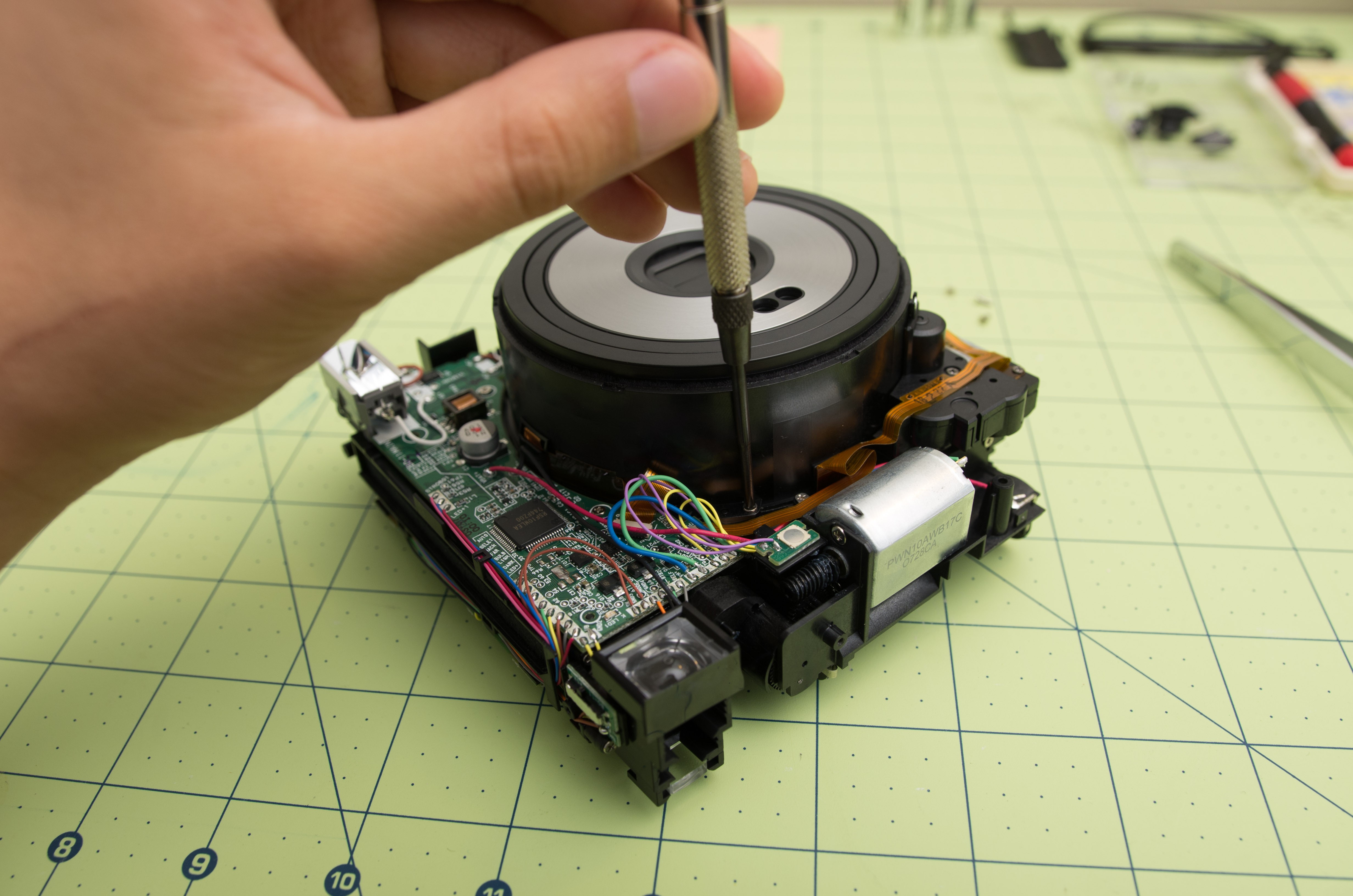
To remove the lens unit, remove the four screws around the periphery of the lens unit:
With that done, you must disconnect the lens unit ribbon cables from the main control board. There are two ribbon cables:
Take a pair of tweezers and gently undo the latches of the ribbon connectors, which are the black features opposite the female end of the connector. Then, you can remove the ribbon cables. Very very little force is required for both of these operations. Don't force anything. A little wiggling here and there will do it.
Separated! At this point, the camera will not turn on. If you try, the main camera unit will flash a pattern of warning lights until you turn it off. It must be expecting some signals from the lens unit (probably the light sensor, flash sensor, and possibly position sensors in the focusing and shutter units).
Now we could slap on our new lens, put it back together, and call it a day, right? Not so fast. As I just mentioned, without the lens unit, the main camera doesn't know what to do with itself. That means no film ejection! Either we'll have to spoof whatever signals are coming from the lens unit, or hijack control of the film eject mechanism. I chose to do the latter.
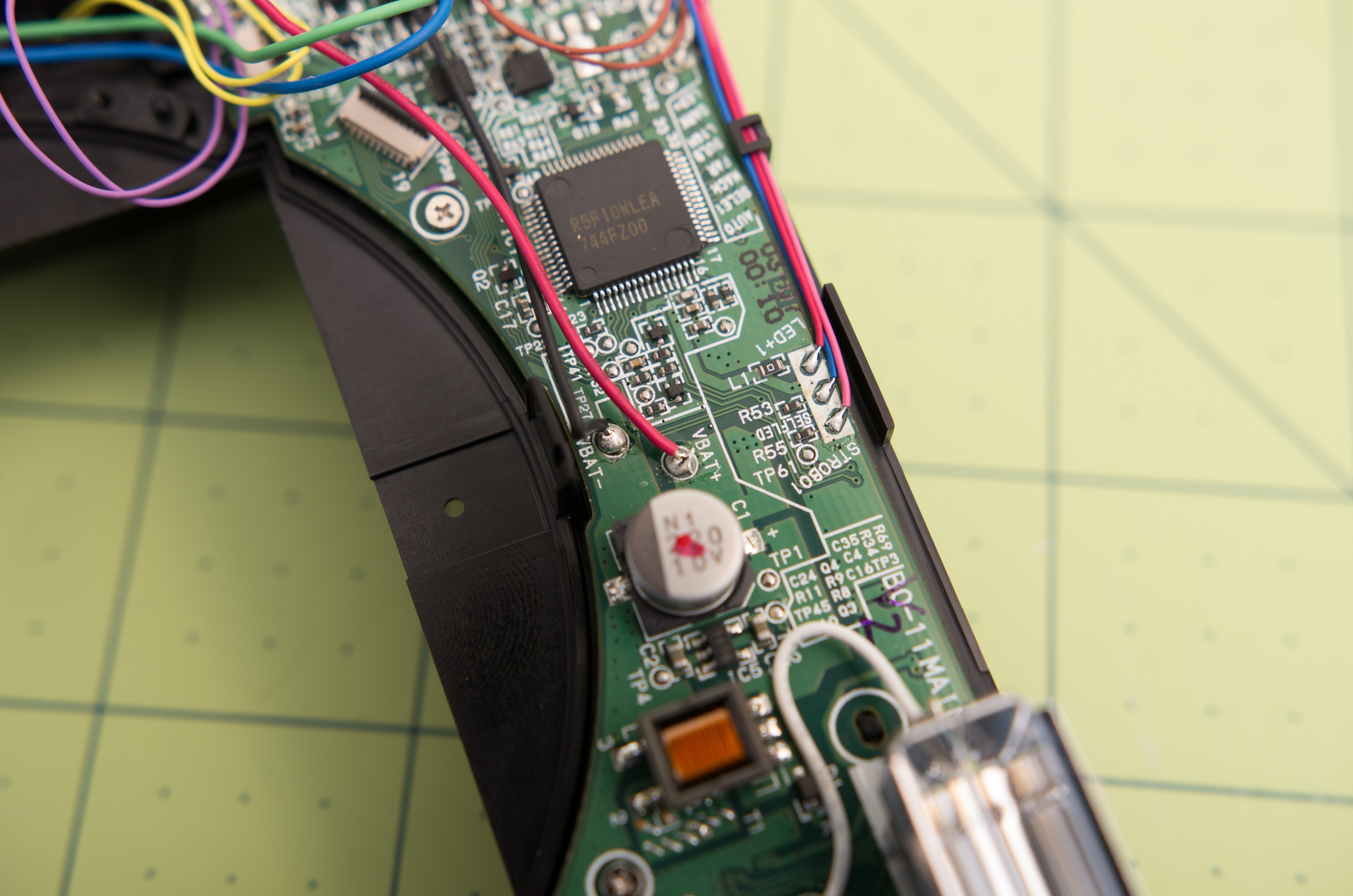
First things first is to identify where the battery power is coming from and going to. The source is pretty obvious, there are leaf spring connections in the battery compartment. These lead to the following two points on the main board, conveniently named VBAT+ and VBAT-;
Next is to identify how the eject mechanism actually works. The whole ejection mechanism is kind of byzantine and I won't try to explain the ins and outs of it here (nor could I do it justice). The gist is:
- The image is captured on the photographic media.
- The ejection motor spins, turning the developing rollers, and also actuating a pick arm, which pushes the piece of film into the rollers and out of the camera.
- As the ejection motor spins, the progress of the film eject maneuver is tracked using a position sensor (a simple momentary switch). When the mechanism is in anything but the rest position, the switch is closed. When it cycles back around to the rest position (pick arm fully retracted), the switch opens. Thus the camera knows when the film eject cycle has completed.
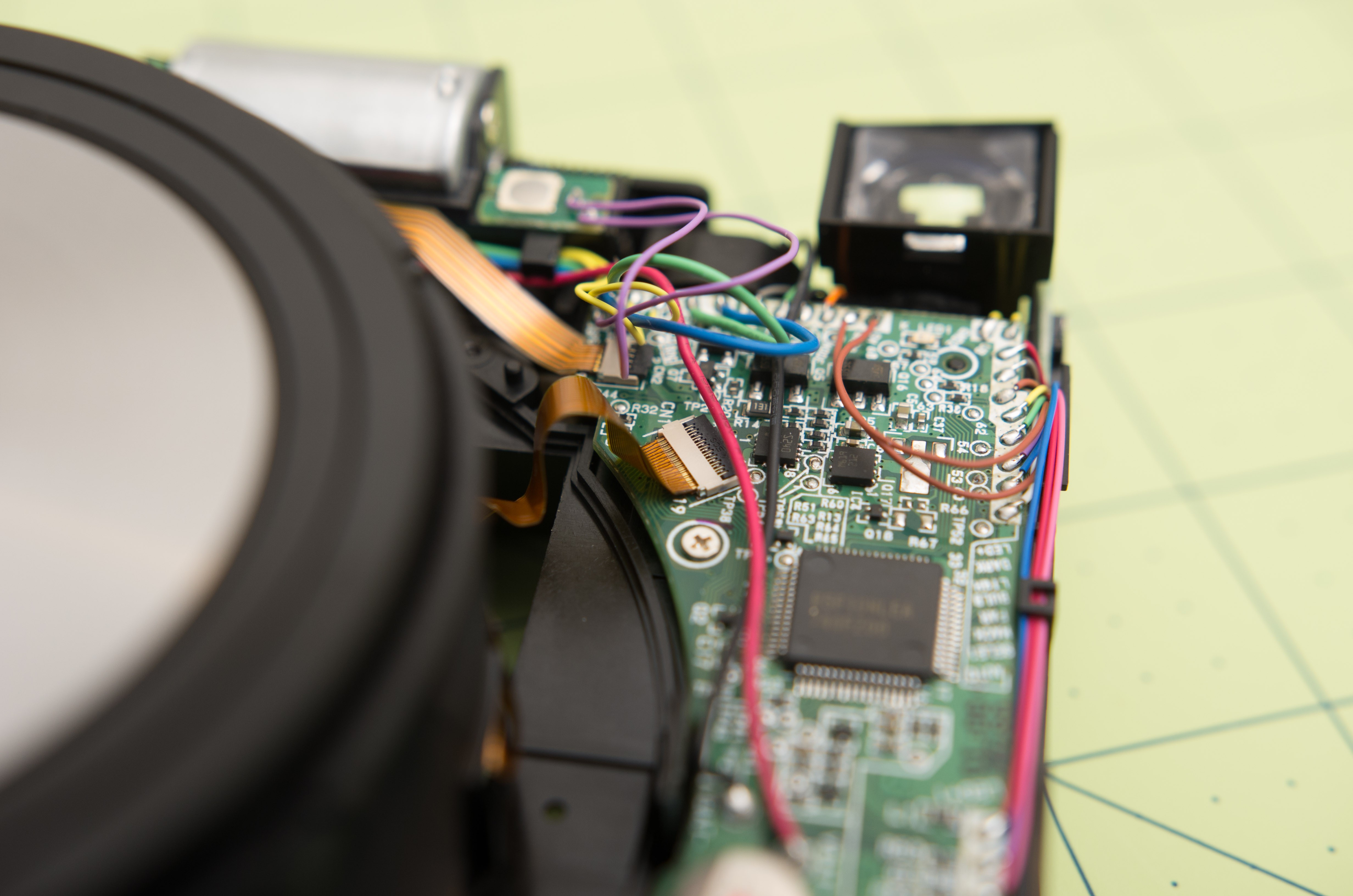
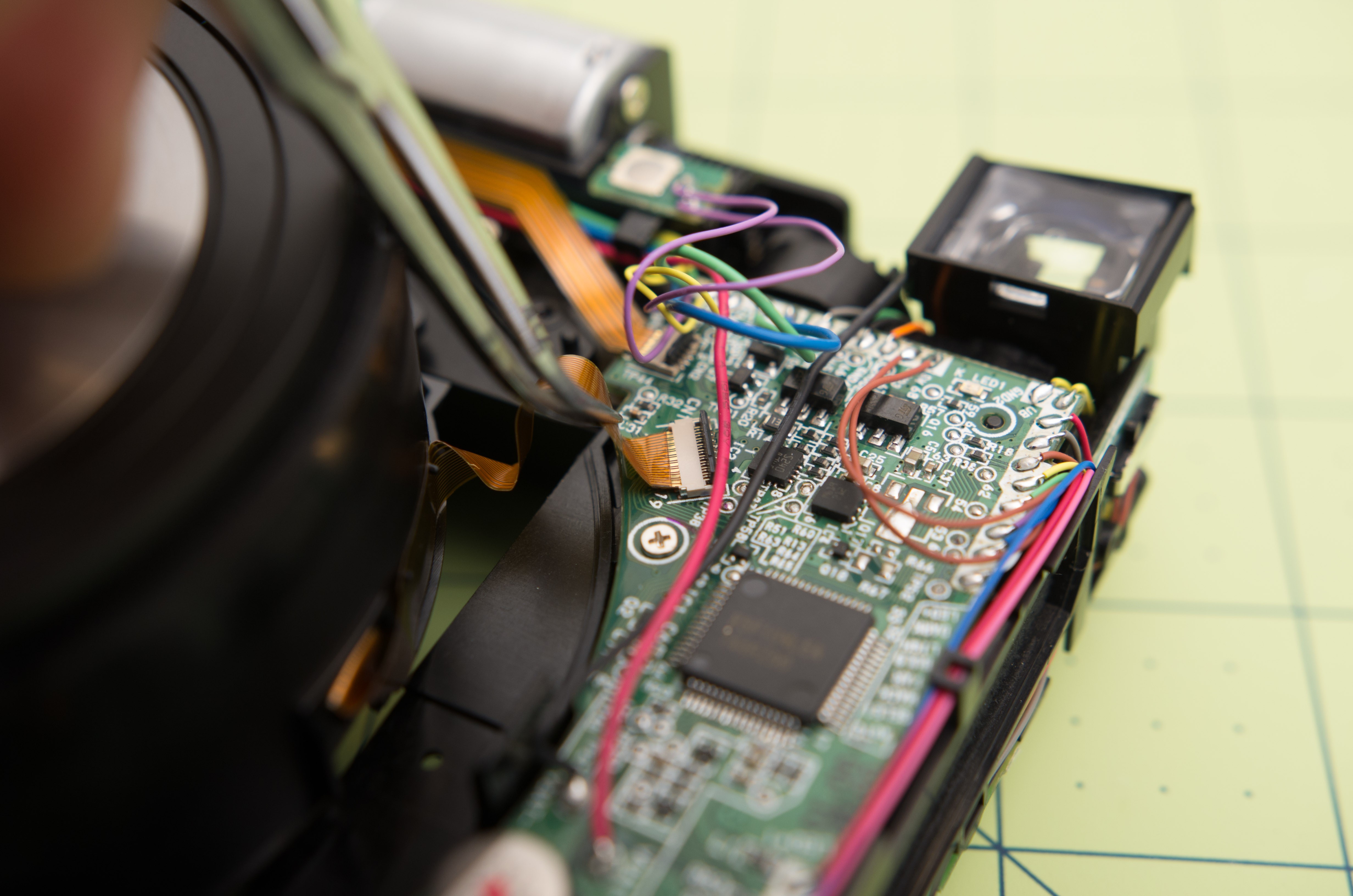
Now I'll turn your attention to the six soldered wire connections at the bottom left of the main board, in the photo below. These are:
- Blue: Motor (+) terminal
- Green: Motor, (-) terminal
- Yellow (2x): Eject mechanism position switch
- Purple (2x): Shutter button

I believe that these are all of the connections needed to control the eject mechanism. My plan is to wire these up to a MOSFET to control the eject mechanism. The flow of the new eject mechanism will be as follows:
- The shutter button (S1) is pressed, turning on the MOSFET (Q1) and allowing current to flow through the eject motor (M1).
- As the eject motor turns, the position switch (S2) is closed, which keeps the MOSFET on even when the shutter button is released.
- The eject motor continues to turn until the position switch opens (when the mechanism returns to its rest position), which turns off the MOSFET and the motor.
That's it! If it works, it will be very simple. I plan to spin up a very simple PCB to facilitate the connections between the MOSFET and the camera wiring.
From here, there are some action items:
- Guesstimate the power requirements of the motor and select an appropriate MOSFET.
- Design and have fabricated (by OSHpark or other) a control board for the eject mechanism.
- Design and have fabricated (by Shapeways, probably) a shroud between the front camera shell and the image plane. This prevents internal reflections and light leaks.
- Measure the flange focal distance of the 80mm f/2.8 lens.
- Order an appropriate helicoid to focus the lens. Should have about ~15mm of travel to accommodate focus down to about 0.5m.
- Design and have fabricated (by Shapeways, again) a piece to connect the camera body and lens + helicoid.
Discussions
Become a Hackaday.io Member
Create an account to leave a comment. Already have an account? Log In.
I am having trouble with the mechanism that turns on the camera. once disassembled lights are on when I insert batteries but the on/off switch does not work. Do you have any ideas on what might be going on?
Are you sure? yes | no
hello, do you know where can I get spare parts? of my dropped my SQ6 and the flash light window cover is broken.
Are you sure? yes | no
Nice work, I look forward to seeing the end result!
Are you sure? yes | no