 Kevin Kadooka
As was mentioned in the last project log, we need to somehow tell the ejection mechanism when to turn the motor on and off - because this is really the only part of the SQ6 that we're interested in using. The camera's main PCB (which normally handles the motor control) does a lot more stuff than that and is pretty complicated - I don't want to mess around with that. Instead I will make a simple surrogate PCB that handles the film ejection.
I also noted in the last update that there's a position sensing switch in the mechanism that opens whenever it has completed a cycle. We can use that, along with the original shutter button, to create what I'm calling the film eject circuit:
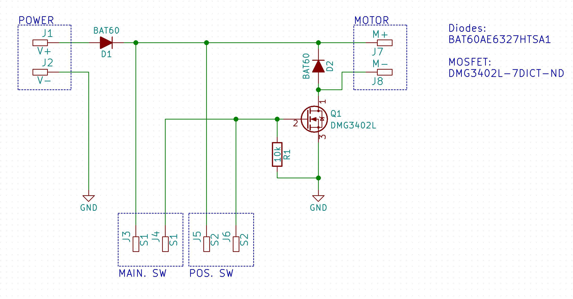
The user presses the shutter button (MAIN. SW), which applies +6V (from the camera batteries) to the N-channel MOSFET's gate pin. This switches on the motor, and as the mechanism moves from the rest position, the position sensor switch (POS. SW) is closed, which keeps the MOSFET gate high and the motor turning. Eventually the mechanism finishes its cycle and the position sensor switch opens, and the MOSFET goes low, turning off the motor (as long as the user has released the shutter button).
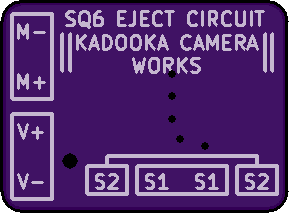
Two Schottky diodes are added for reverse polarity protection and as a flyback diode, for good measure. By choosing some modestly-sized SMD components, the resulting board measures only 10 mm x 14 mm and will slot in easily inside of the camera body:

The best part is, 3 PCB's only cost $2.40 from OSHpark (even with their Super Swift Service)!
Discussions
Become a Hackaday.io Member
Create an account to leave a comment. Already have an account? Log In.