 blinkingthing
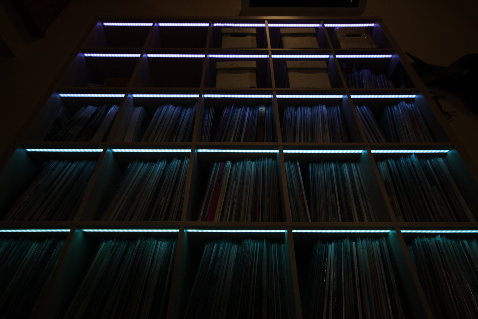
I recently moved house and wanted to upgrade my recordShelf as part of the transition. This update will focusly mainly on hardware and IKEA furniture modification.
In my previous google searches looking for IKEA Expedit or Kallax shelves with lighting set-ups I found this page with a beautifully modified shelf with recessed LED strips in each shelf. It looked so much cleaner than my set up and I wanted to emulate it the best I could. The woodworking challenges presented to me were the pretty difficult for me as I've never used a router and I needed to do a lot of routing for this project.
3 weekends back, IKEA had a sale on the particular shelf I was after and I decided it was time to begin this project. I got the shelf, brought it home, opened up the packaging and started to get a plan together.
Routing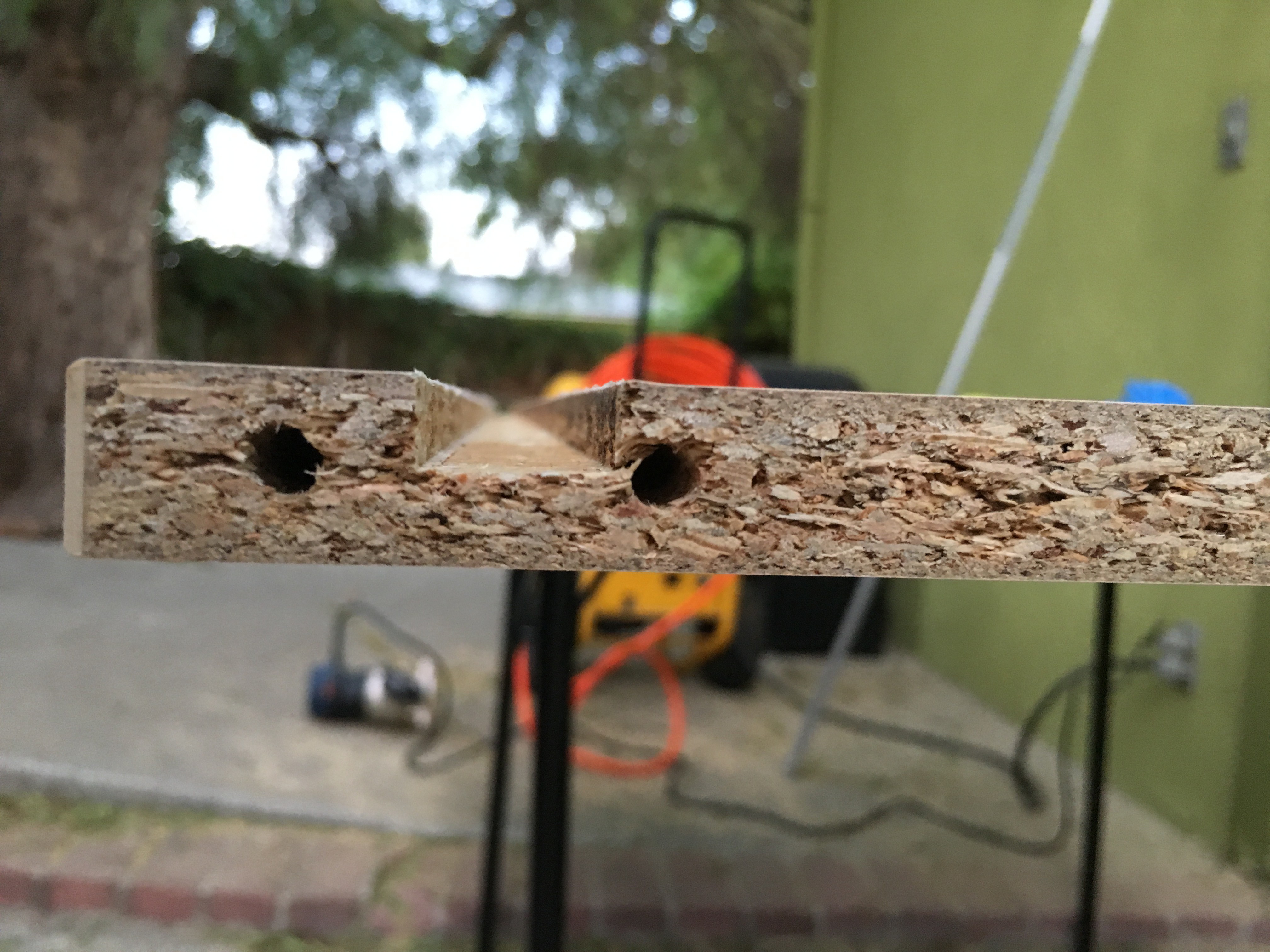
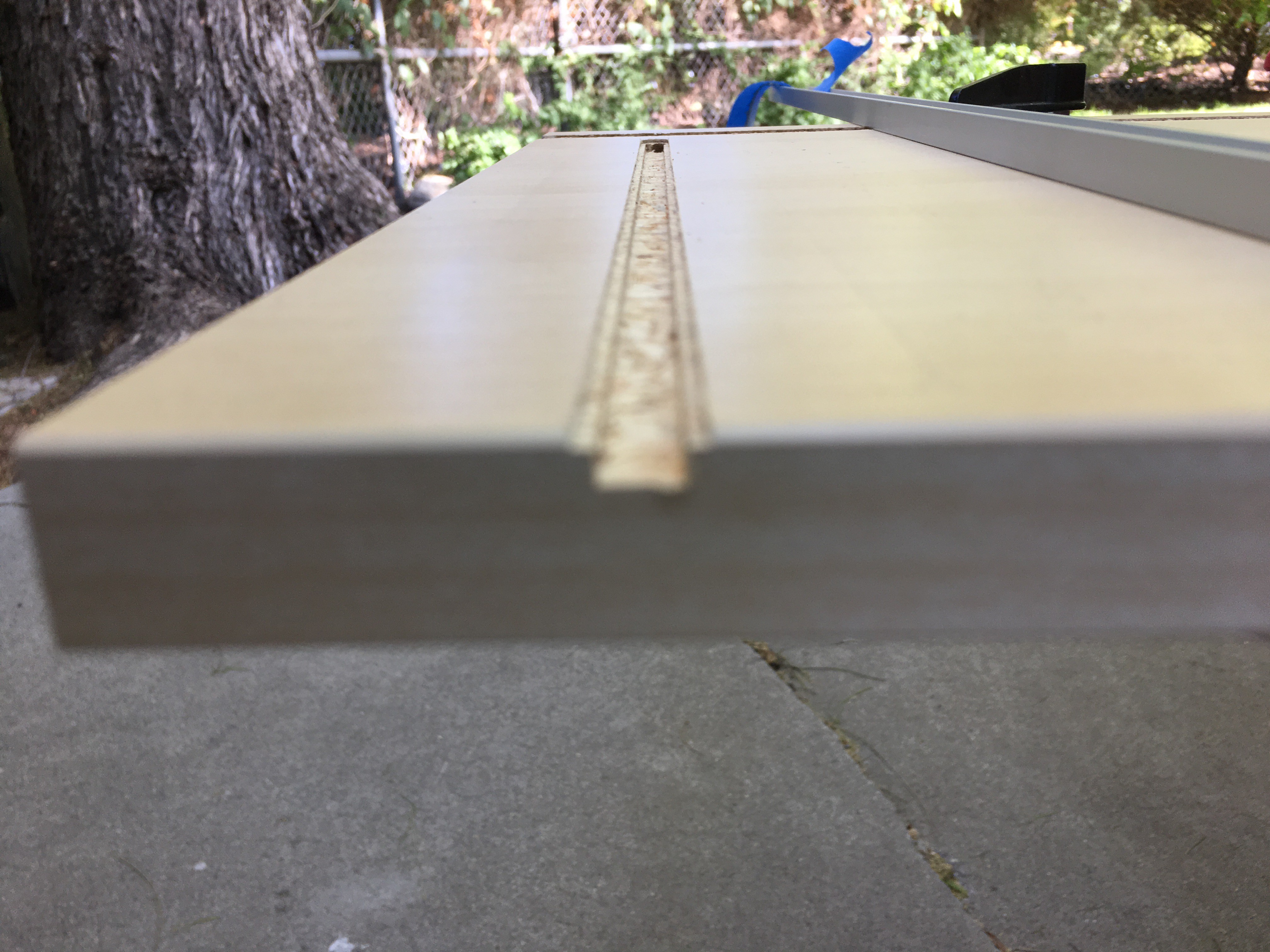
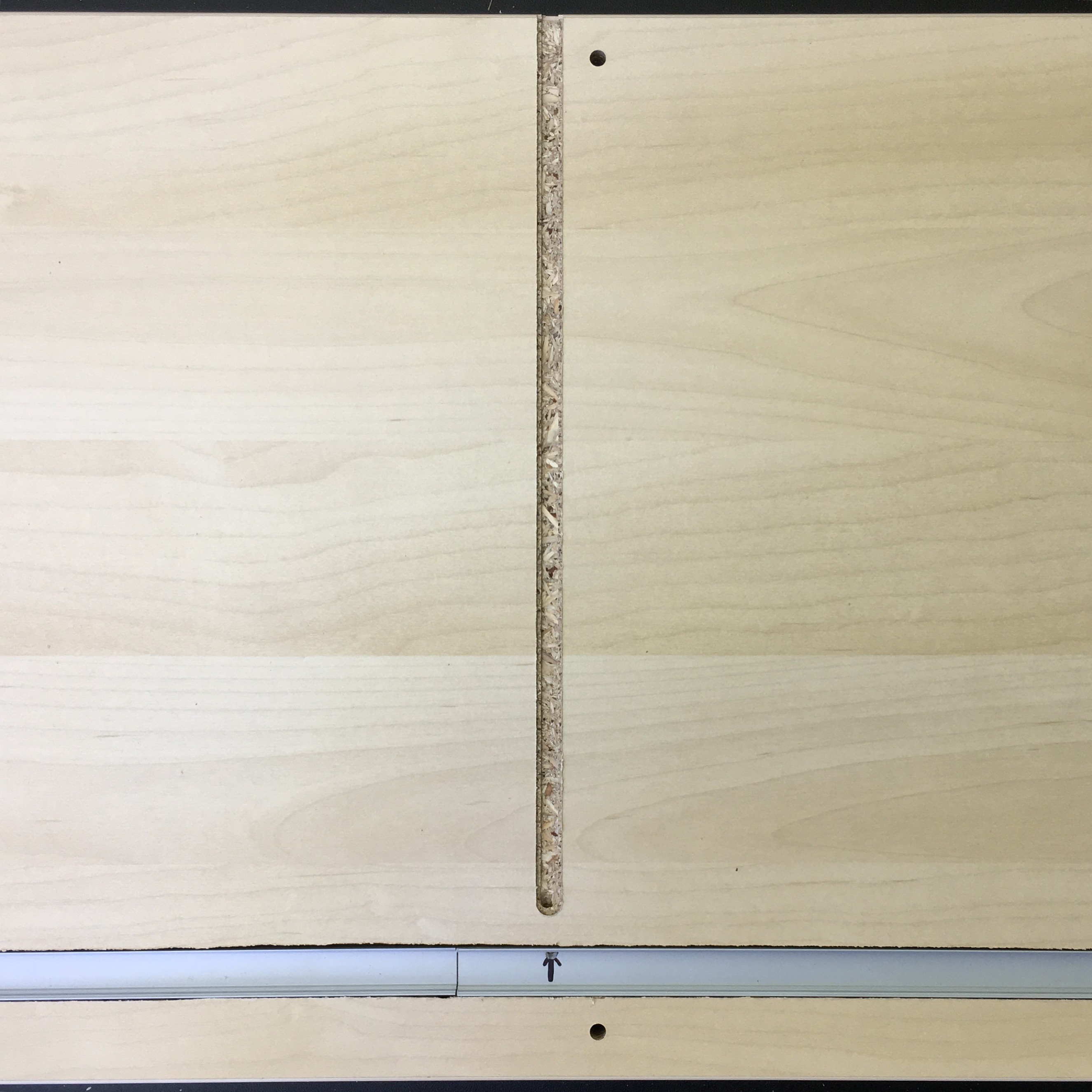
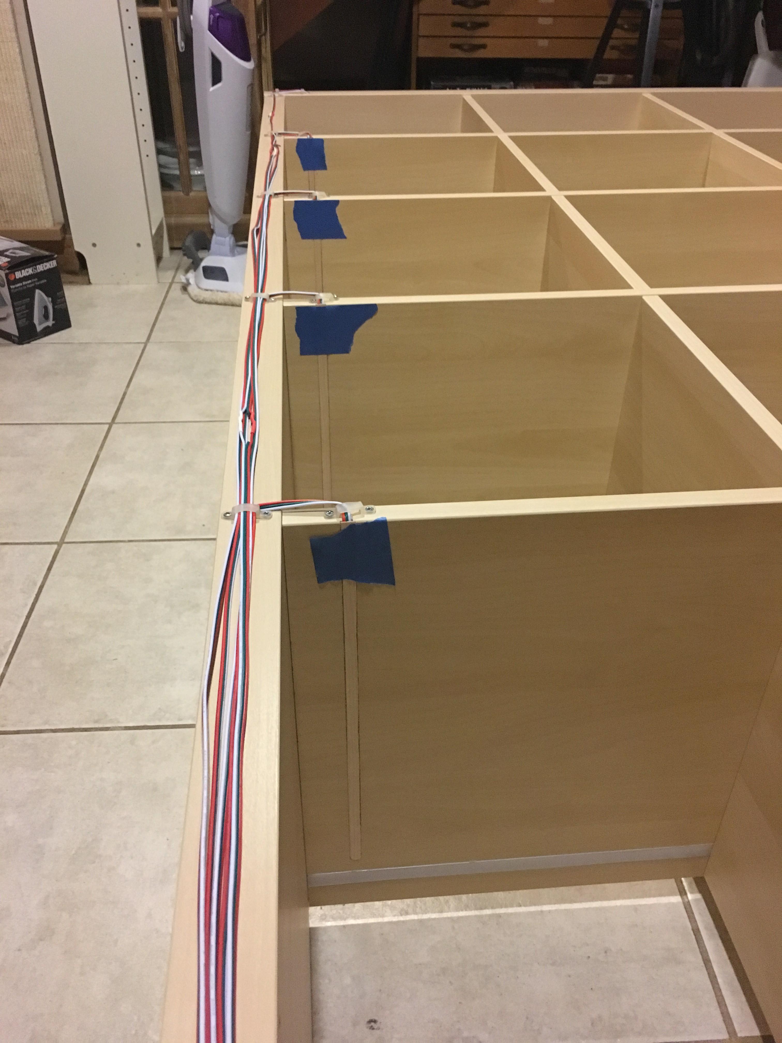
To decide on where to put the channel for the LED strip I looked at my old lighting setup and measured how far back I had mounted them. The distance ended up landing between the two holes that receive pegs as part of the shelfs assembly. I covered the line I'd be routing out with blue painters tape to help reduce the amount of chipping of the laminate/veneer.
I then needed to drill holes at an angle from the inside of the LED channel towards the back of the shelf where the wires would run. There were three locations on each shelf/LED strip where wires would attach and run back so I needed three of these holes on each shelf. I only punched through the wrong side by drilling too far on one of the fifteen holes I had to make.
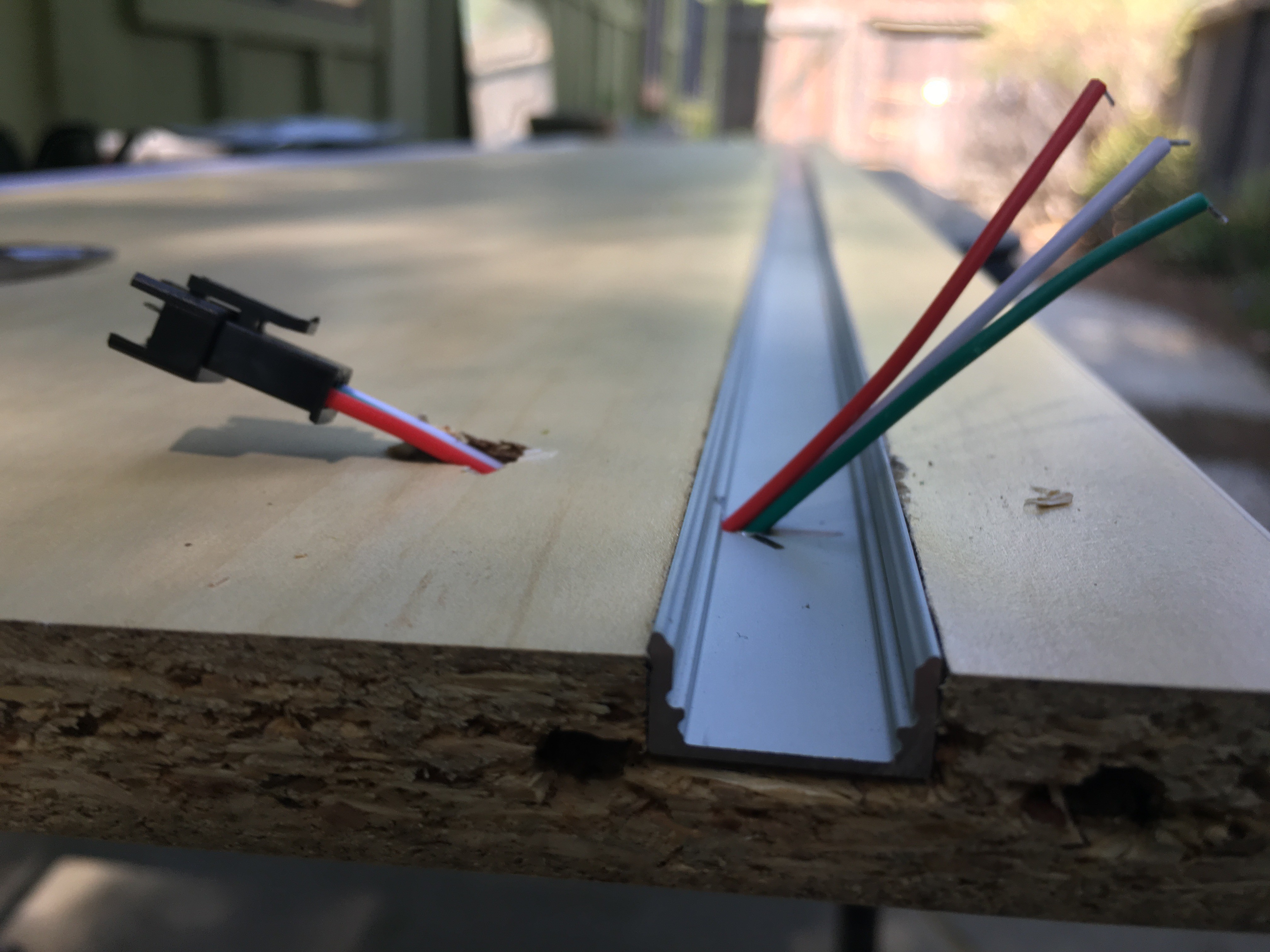
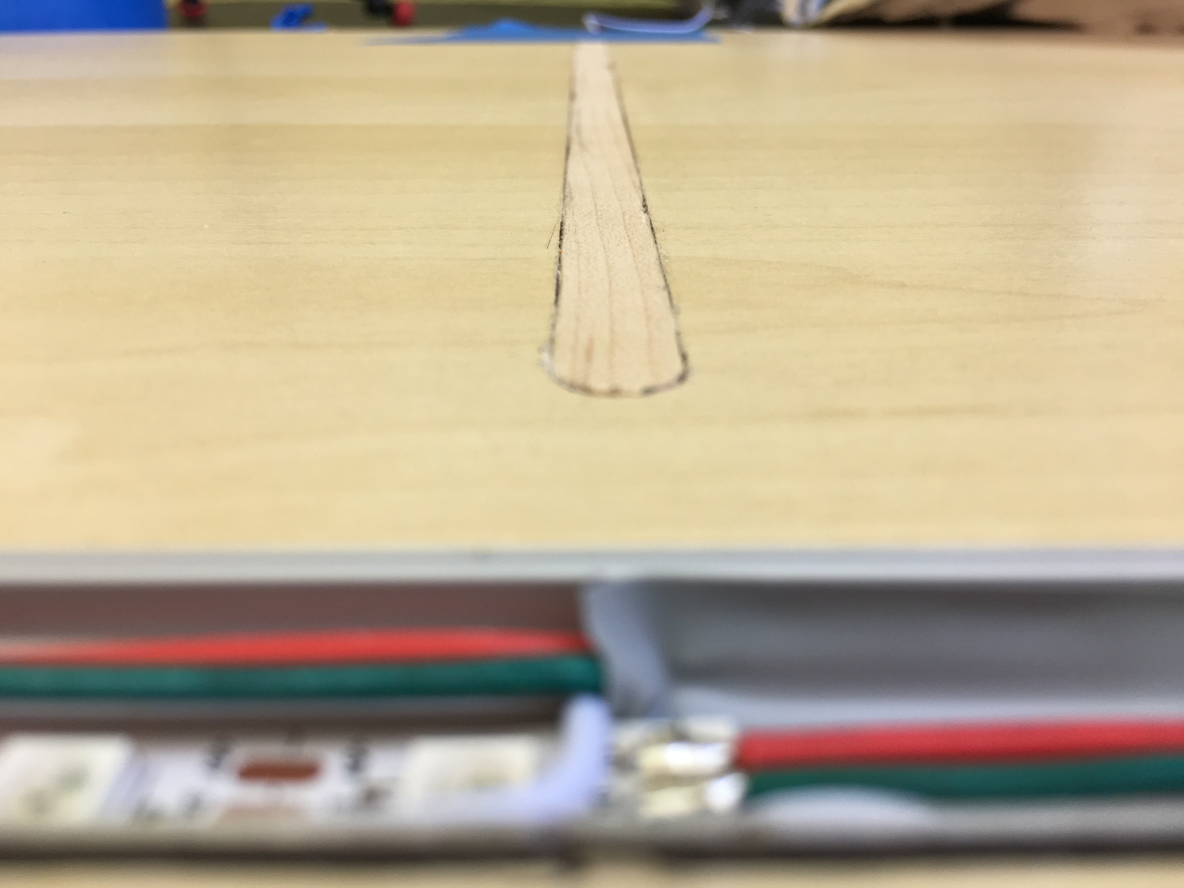
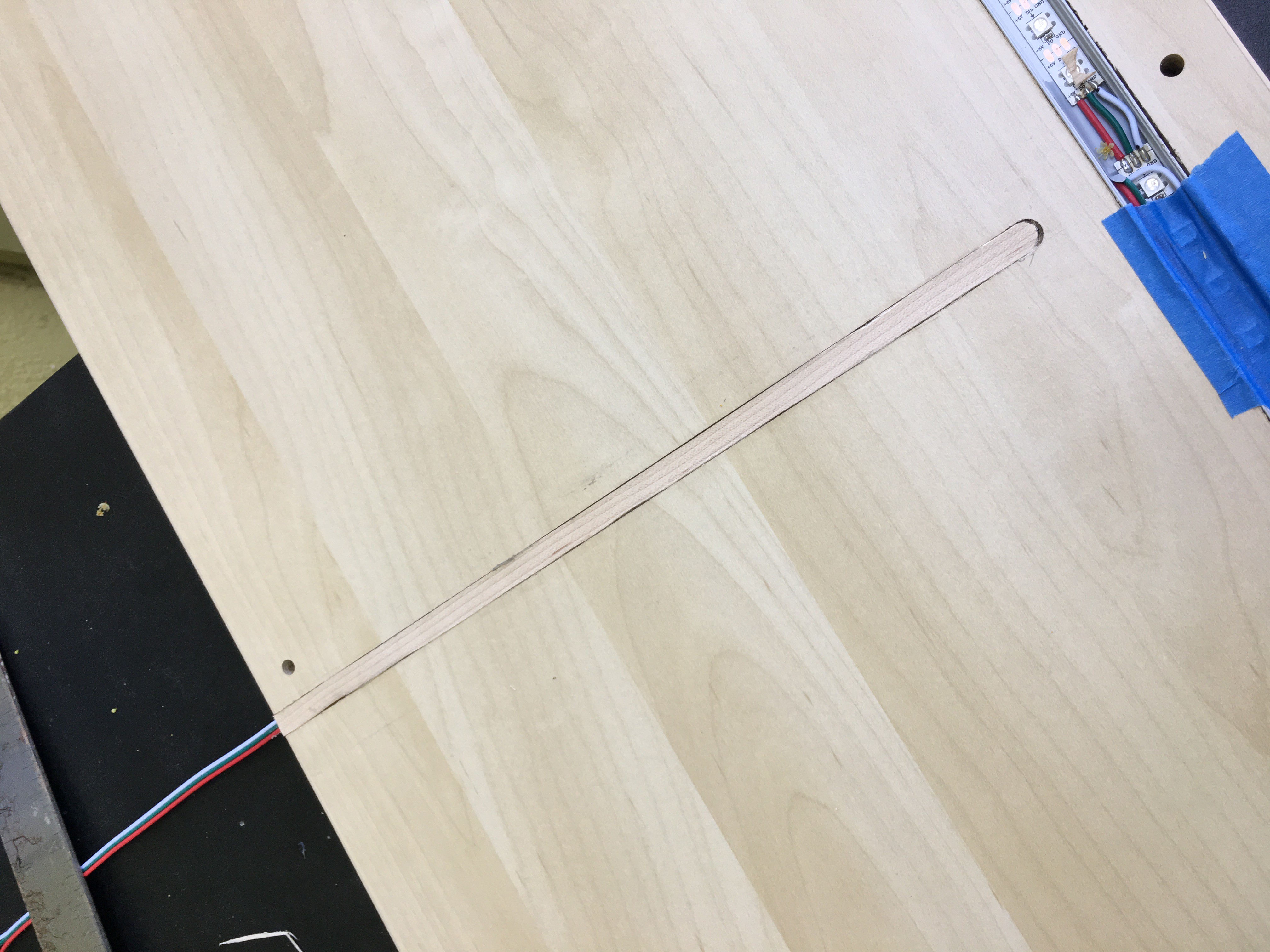
To keep a clean look, I wanted to also route out channels for the wires to run back towards the back of the shelf. This channel would require two passes with the router as I wanted to create a little shoulder or ledge that I could attach a finishing piece to, to hide the wiring. This turned out quite well with the inner channel being just wide enough to accept the 3-wire cable I'm using.
Prepping LED Strips
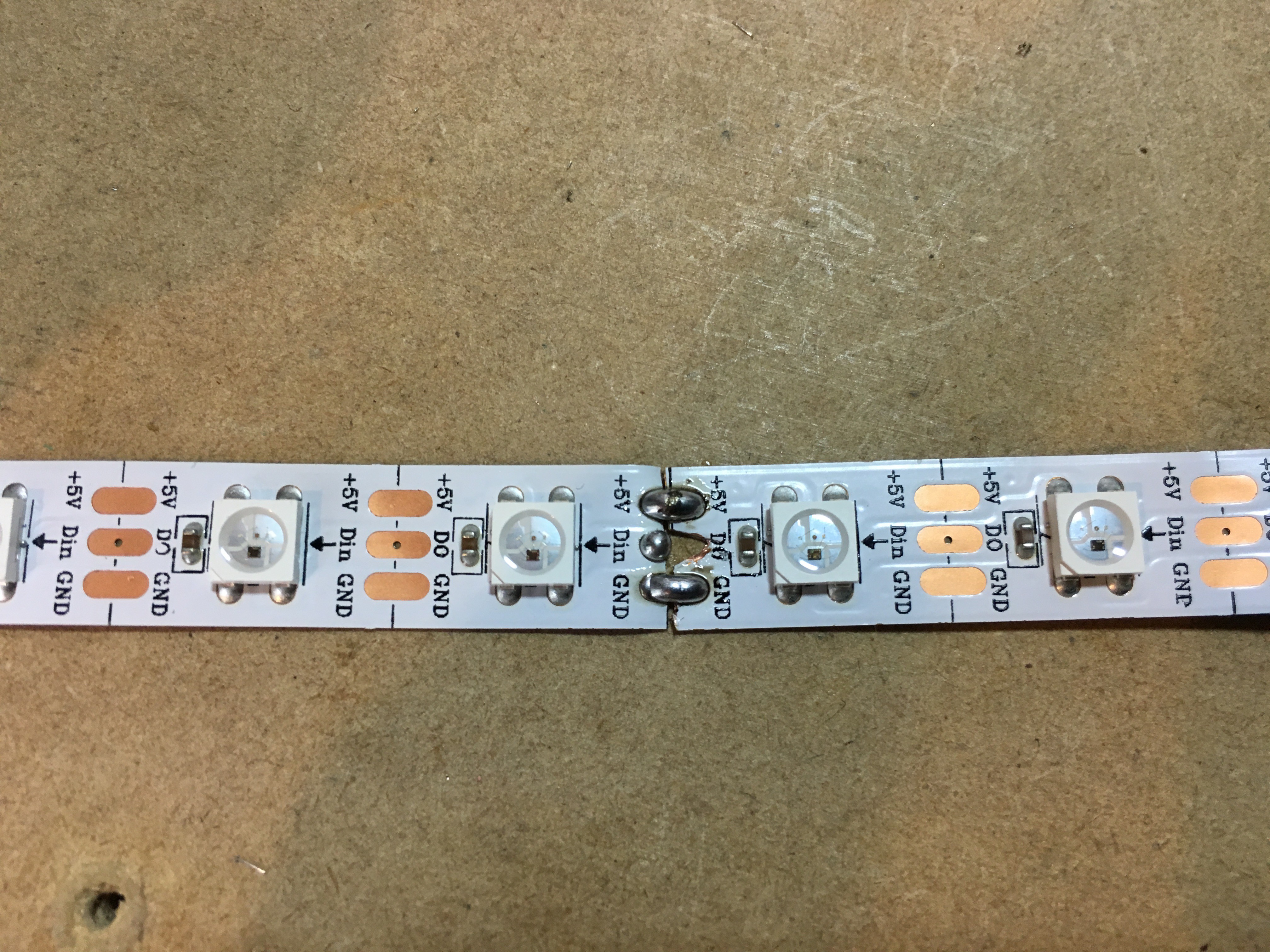
The LED's I chose are the same that I've been using in past versions of the shelf. WS2812b's with a resolution of 60 pixels per meter. This breaks down to 20 pixels fitting nicely in each individual box of the shelf. I could've just left the strip as one long continuous piece for each shelf but I opted to space out strips of 20 evenly with small jumpers inbetween so that the LED's would fall perfectly between the vertical supports on each horizontal shelf.
Another caveat with the wiring and prepping of the LED strips was that I had to consider the data limitations of the Fadecandy board that I was planning on using. The fadecandy can power up to 512 pixels, 64 per output, 8 outputs. This meant that while one single fadecandy could run all 500 pixels on my shelf, it would cause some really odd runs and daisy chaning together of led strip in order to get the data topology seperated into 8 sections that were less than 64 each. Instead, I opted to add a 2nd fadecandy, and to use 10 seperate data runs that each handled 50 pixels. This meant a more simple wiring scheme with one data line running to the first pixel on each shelf as well as the 51st pixel, exactly in the middle each shelf. To insert a data line into the center of each strip, I cut the full assembled strip in half, and then remade the + and - power connections but didn't bridge the data, instead running a new data line to be inserted at that point.
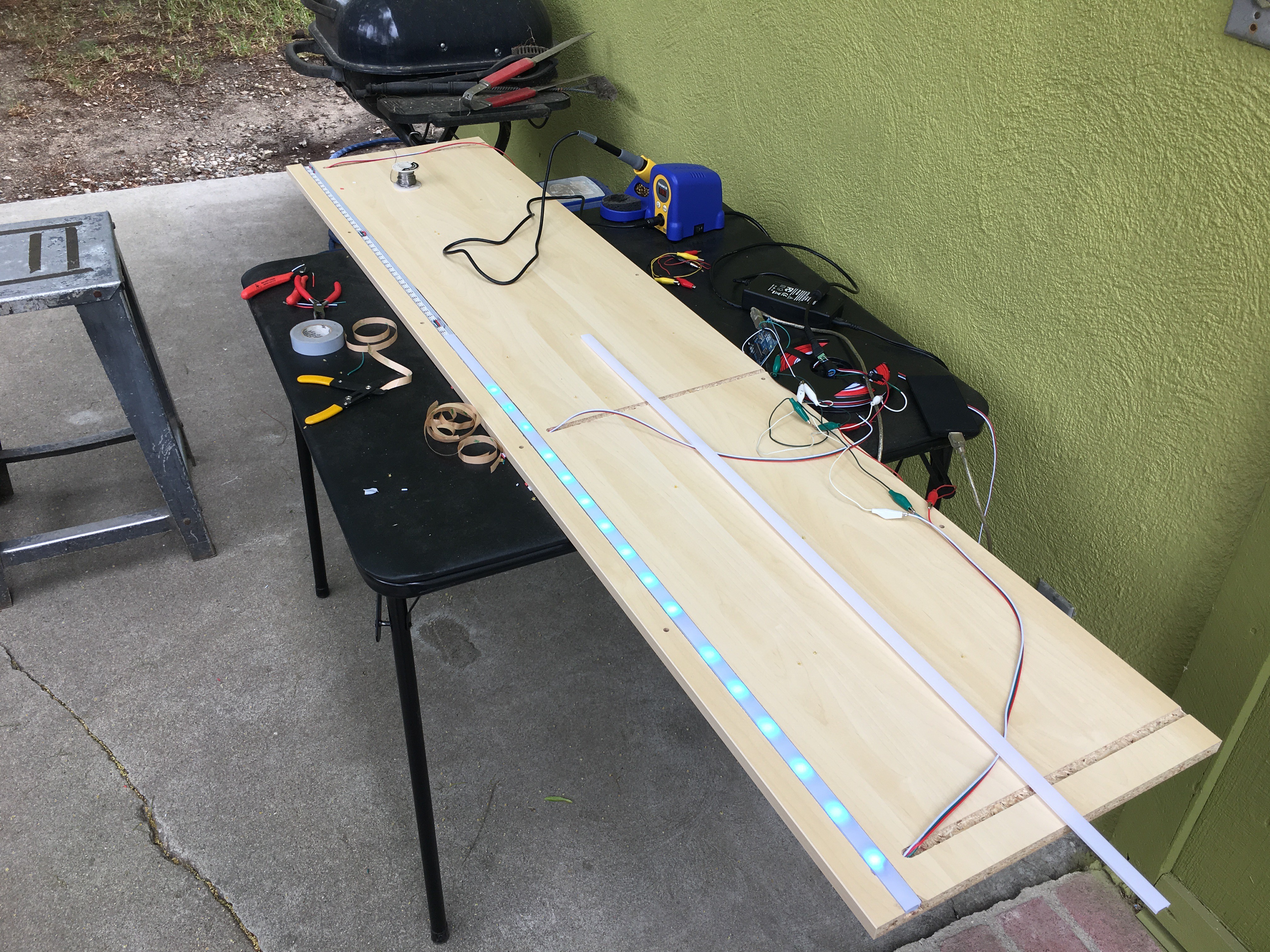
At this point I needed to test the LED strips using the hidden wiring running through each shelf before moving too much further with assembly. Keep in mind I tested the fresh rolls when they were shipped and they all checked out then, but I checked the strips at many points throughout this build to ensure that all the soldering/wiring I was doing was good.
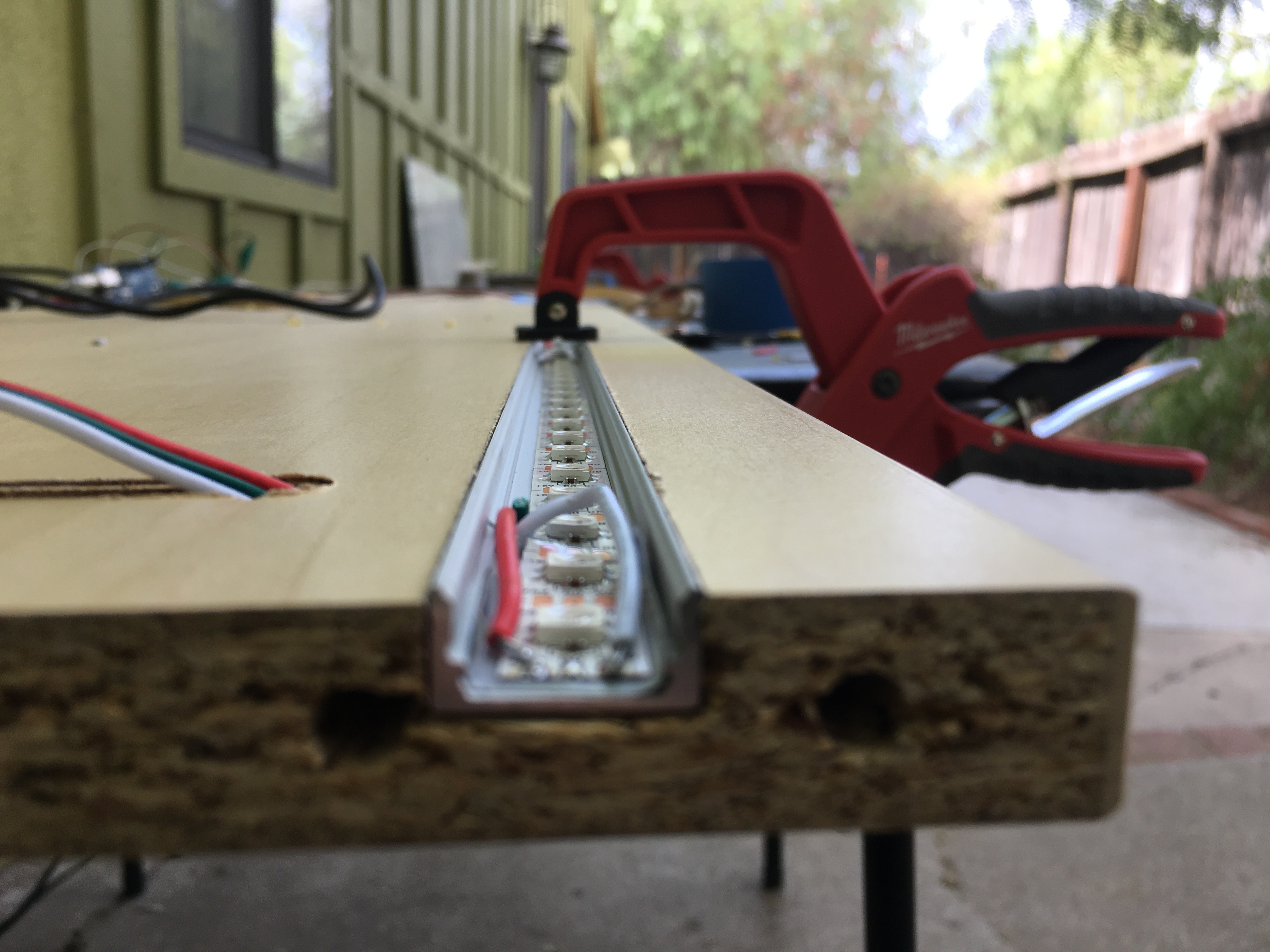
Silicon Adhesive
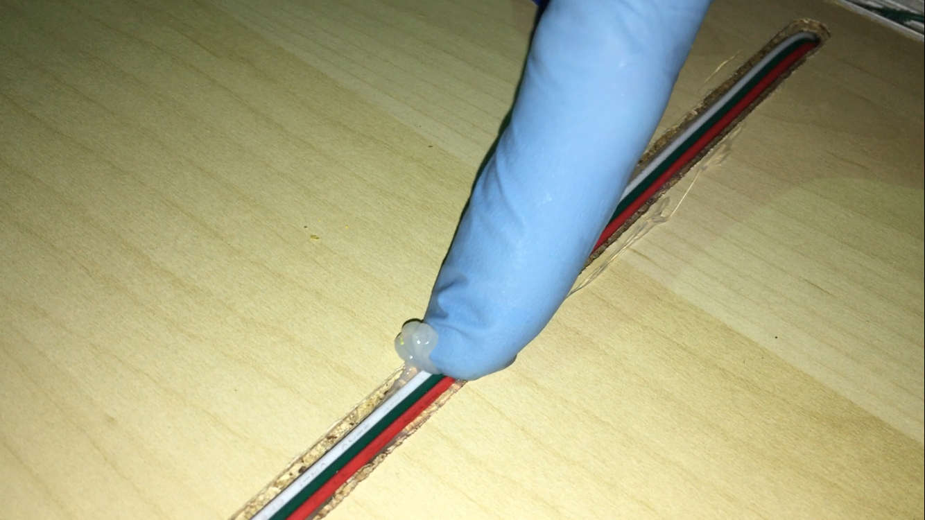
With the LED's all checked out, the next step was to permanently adhere the LED strips to the aluminum channel, the aluminum channel to the shelf and all wiring to the shelf. The LED strip was delivered with 3M tape on the back so that was relatively easy to peel off and stick to the inside of the channel. For the aluminum channel I laid down a line of adhesive in the routed out wood, pressed the channel inside, clamped the channel in lightly and cleaned up any excess adhesive that squeezed out the sides. For the wires that run to the back of the shelf I put a bead of adhesive down and then pushed the wiring down into the adhesive covered channel with a glove covered finger to smooth it all out. This worked out extremely well.
Veneer Tape
Next I used yet another new process to help cover the wiring on the shelf. I discovered a product called veneer tape that is a thin roll of wood with pre-glued backing that is meant to finish the raw edges of cabinetry. I cut a strip to fit the channel I had routed out and used a clothes iron with a sheet of aluminum foil between it and the work to warm up the veneer tape's glue. It took a little figuring out but the end result was quite nice.
Lens Cap
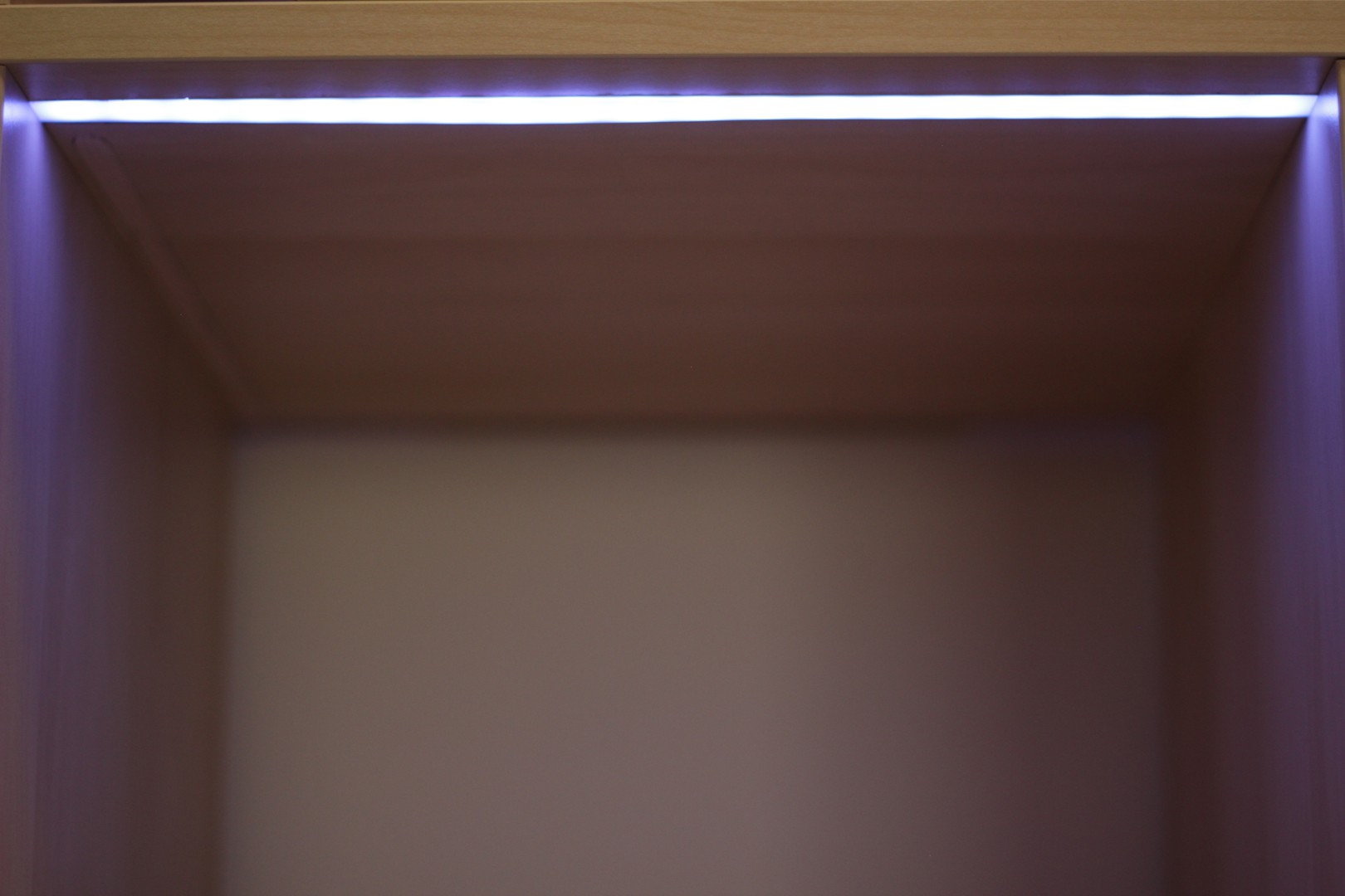
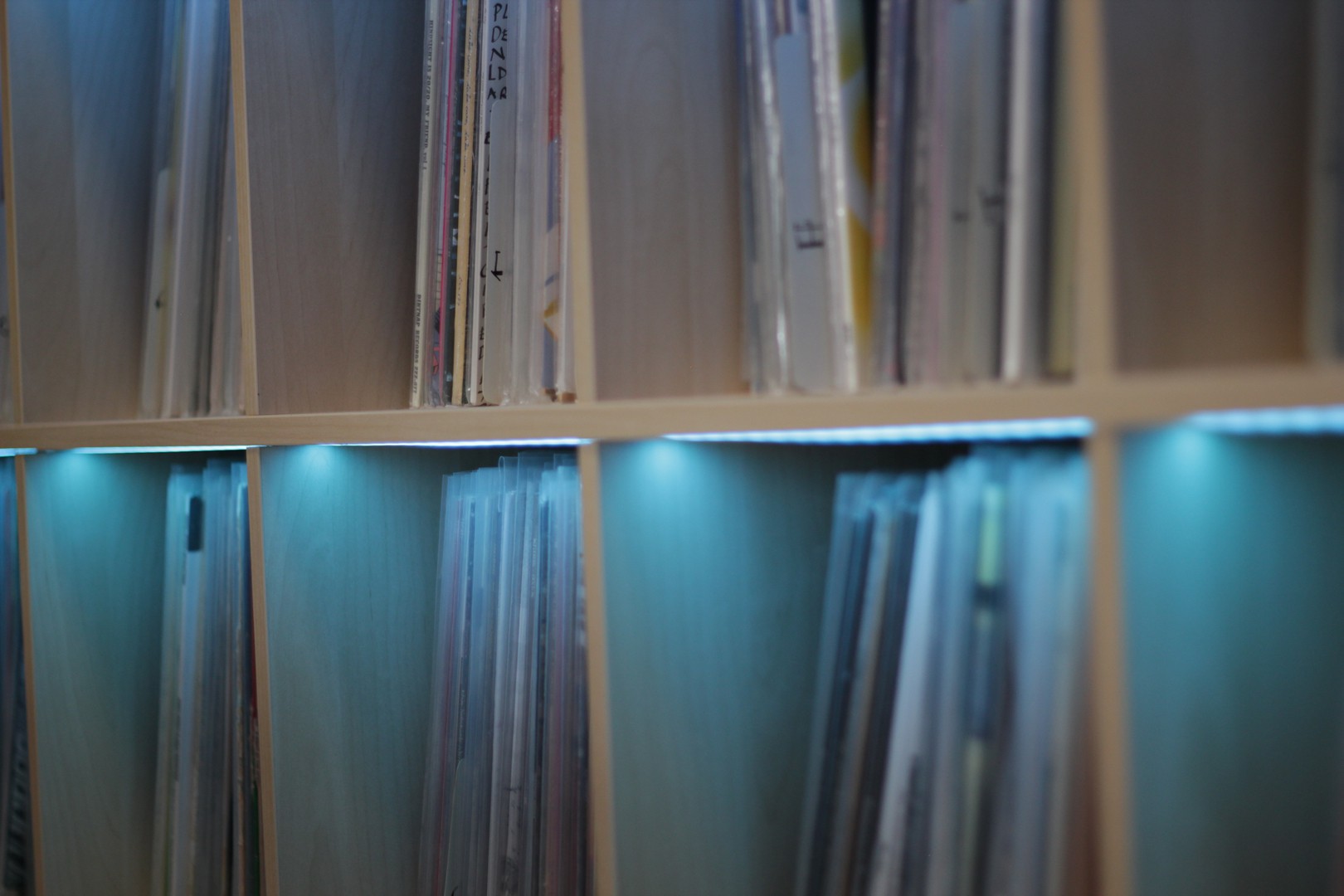
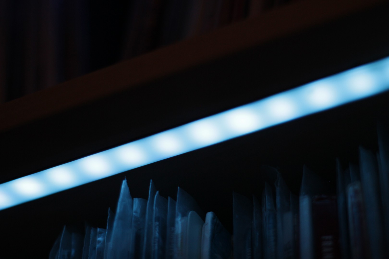
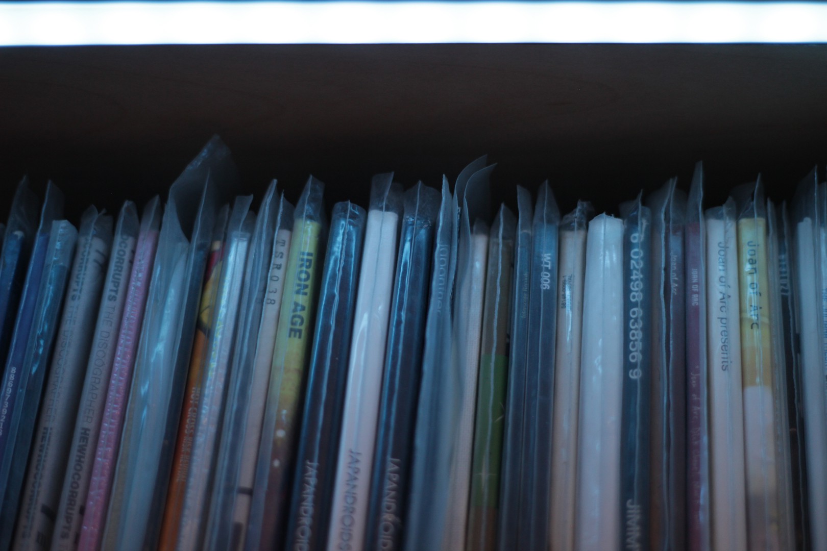
The last step of prepping the shelves was to install all the frosted lens caps that will mask the source of the light. When I installed them and turned the lights on, I realized that you could see some of the wiring that was running inside the channel with the LED strip and decided to use some silicon adhesive to clean it up. The end result was definitely as clean as I was hoping it would be.

Power
I then shifted to working out a safe power supply solution. The max DC draw of the 500 pixels at 5v was 30A. I This is what fueled my initial decision to use (2) 20A supplies. These two supplies are wired parallel to AC mains. Each supply has (2) 5v out's. I wired each of the 5v outs through a 10A glass fuse to a terminal block where I will attach the power leads coming off the LED strips. I distributed the LED's as evenly as I could across the (4) 5v 10A outputs I had to work with. All the power equipment was wired together and mounted on a separate piece of wood so I could do this work on my workbench then attach it to the underside of the shelf later.

Shelf Assembly / Wiring
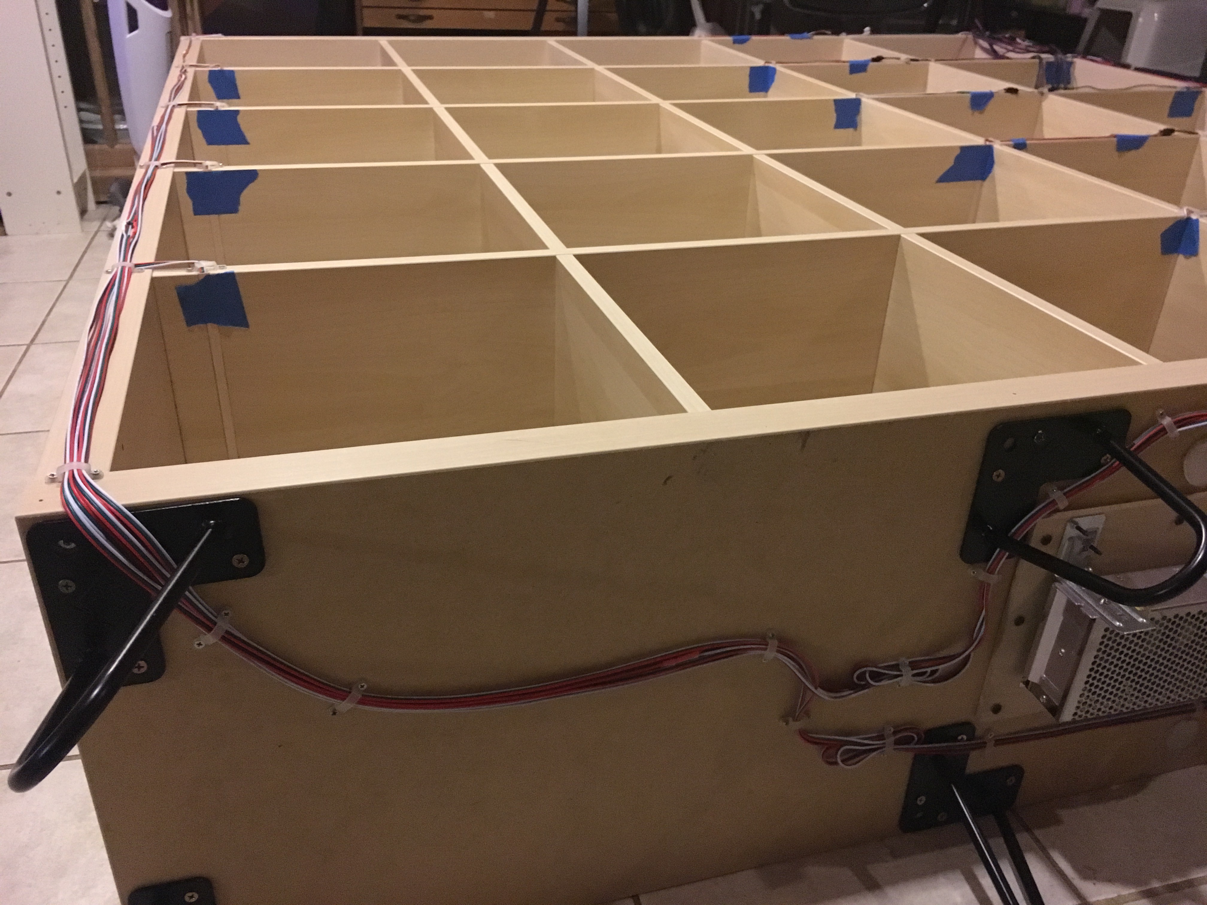
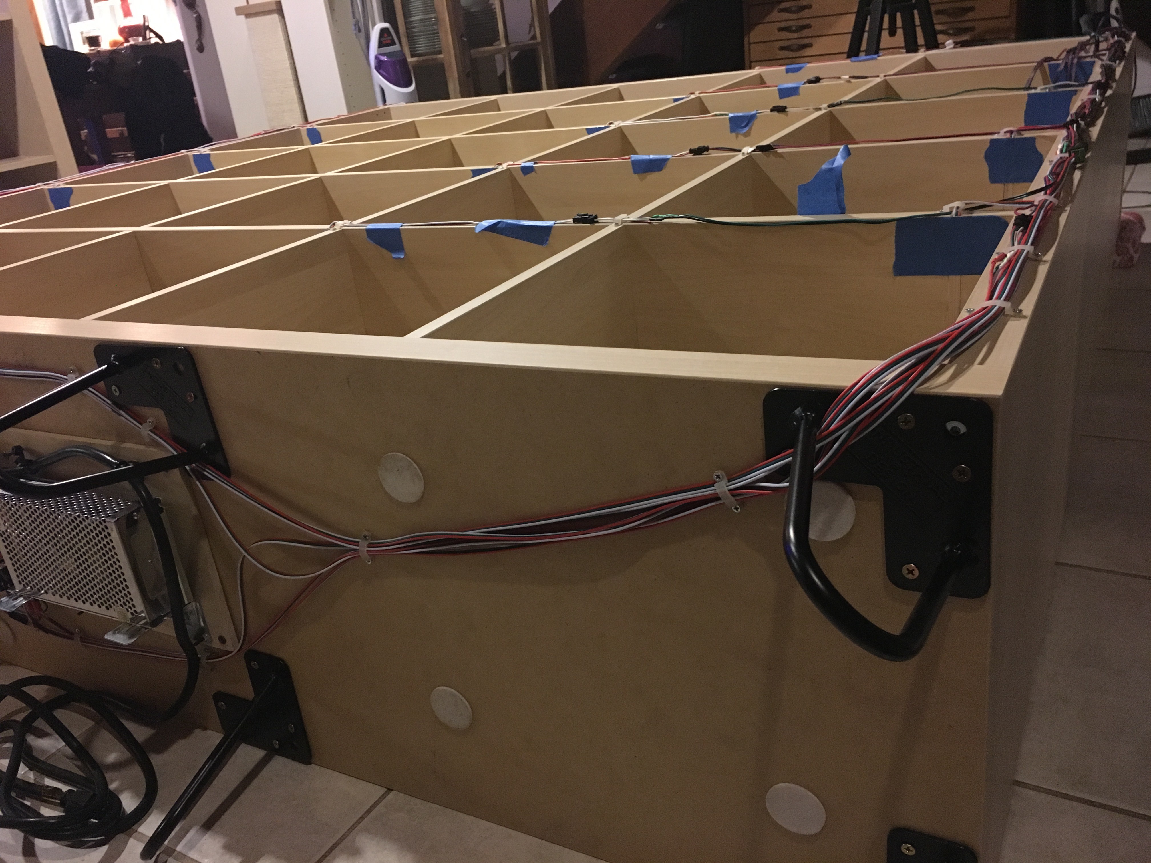
I didn't take any pictures of the normal steps that anyone has seen if they've built IKEA furniture before. Nothing exciting happened then. I just built the shelf face down so I had the side with the wiring facing up for easy access. I routed the wiring out the back of the shelf and out to the sides, keeping it clean with silicon U-brackets I have for mounting LED strip but I think they work well for tidying up the wiring.
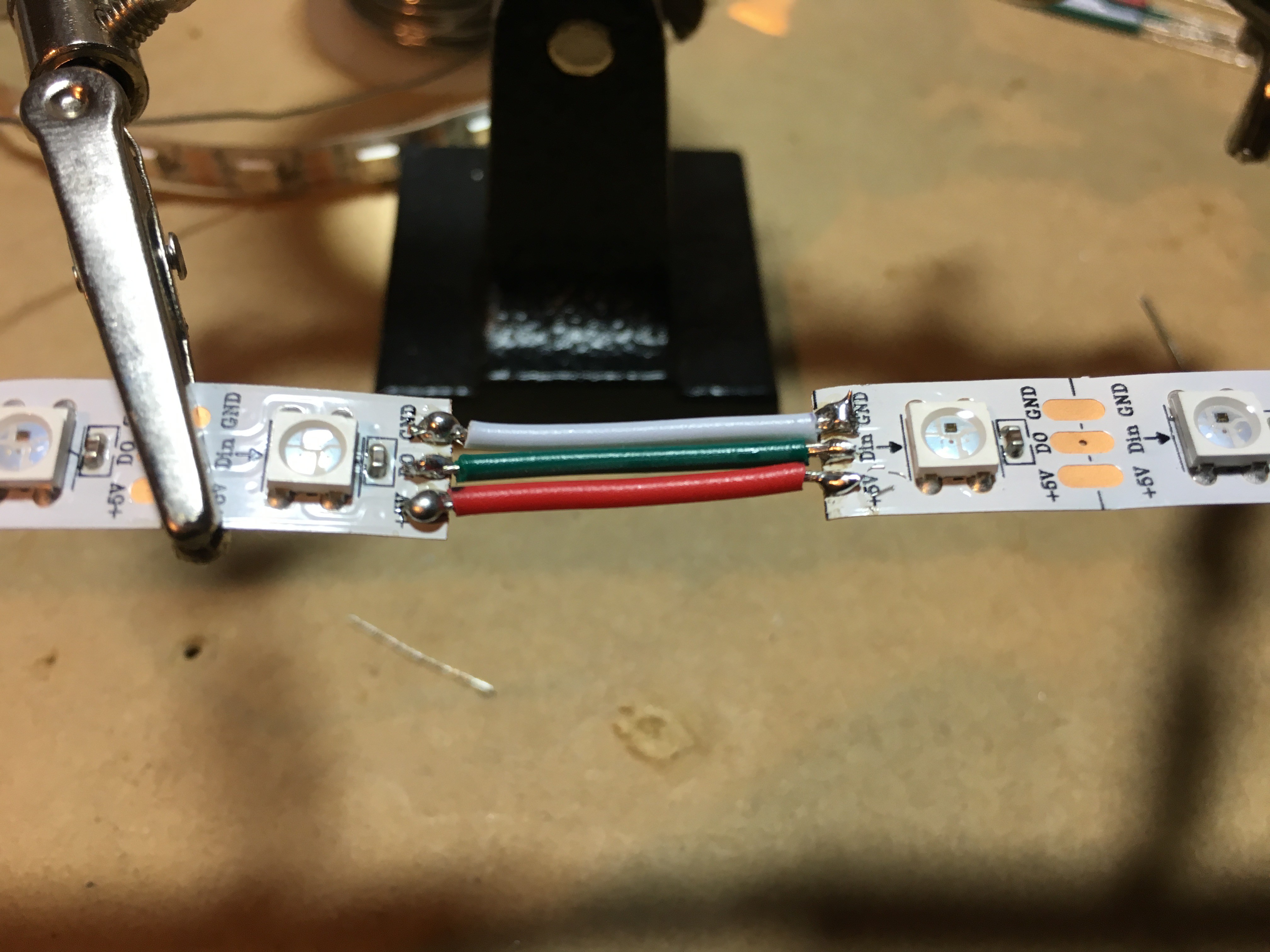
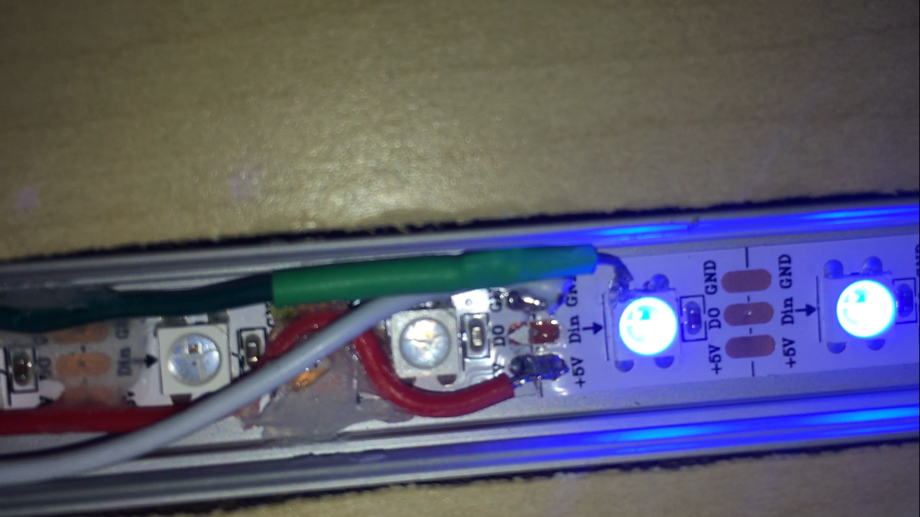
At this point, I stood the shelf up and wanted to test the wiring in its current state before wiring and mounting the power supply in its final position. I ended up having a bad data connection! Luckily it was in the center of a strip that was accessible by peeling off the frosted lens cover. I had to do some upside-down soldering, moving a data lead that had ripped off the copper pad from which it was attached directly to one of the leads on the LED's. Here's the best picture I could get of my handy-work. The green cable had to be extended/heat shrunk/attached to the LED (it had been attached to "Din" previously). This is also a good illustration of the silicon adhesive cable management I had done earlier.
Final Power Wiring / Assembly
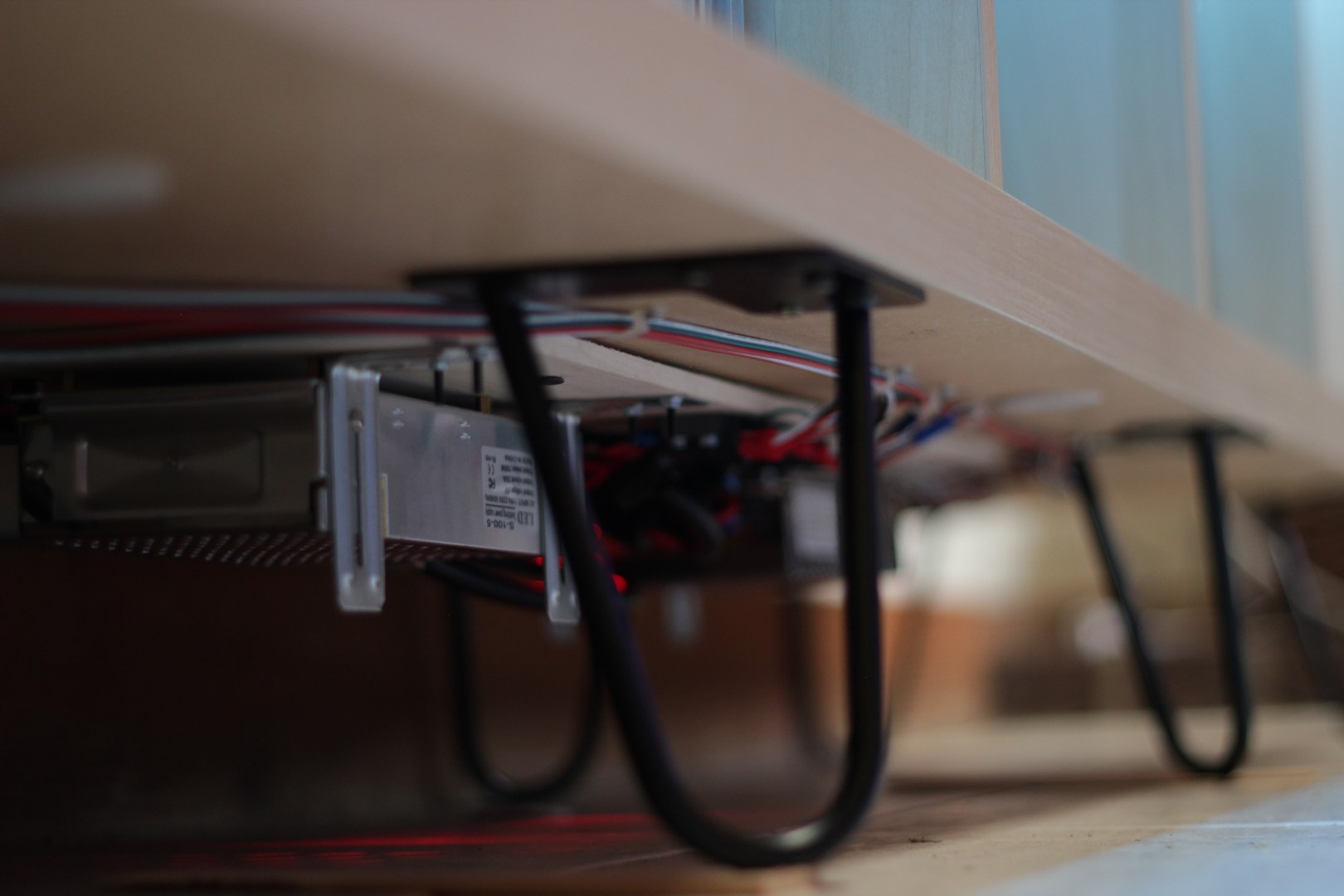
With everything checked out, I laid the shelf back on it's face and attached the power panel as well as some trendy hairpin legs to the bottom of the shelf and got all the final wiring cleaned up using silicon U clips.

First Full Power Up / Delving into Software
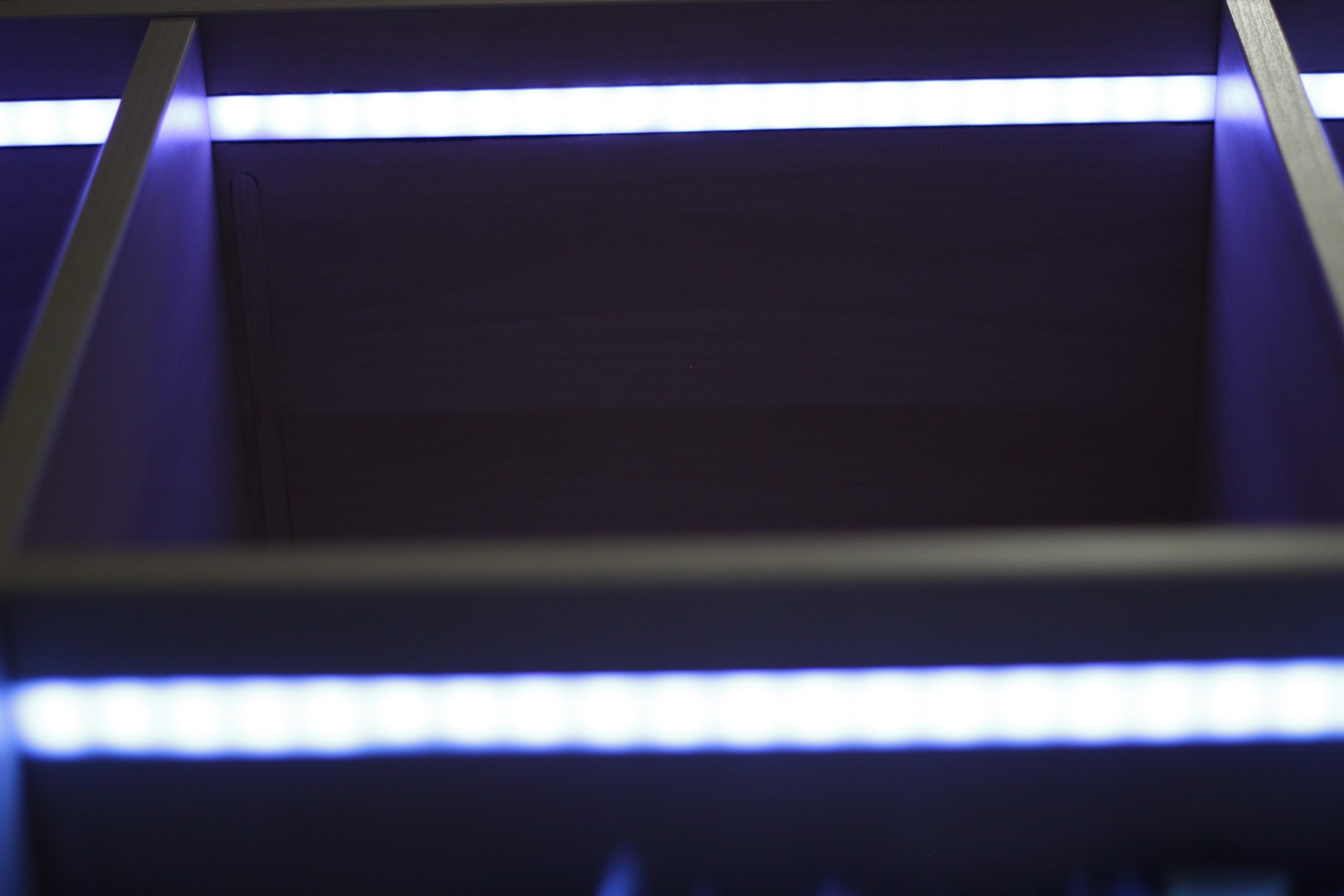
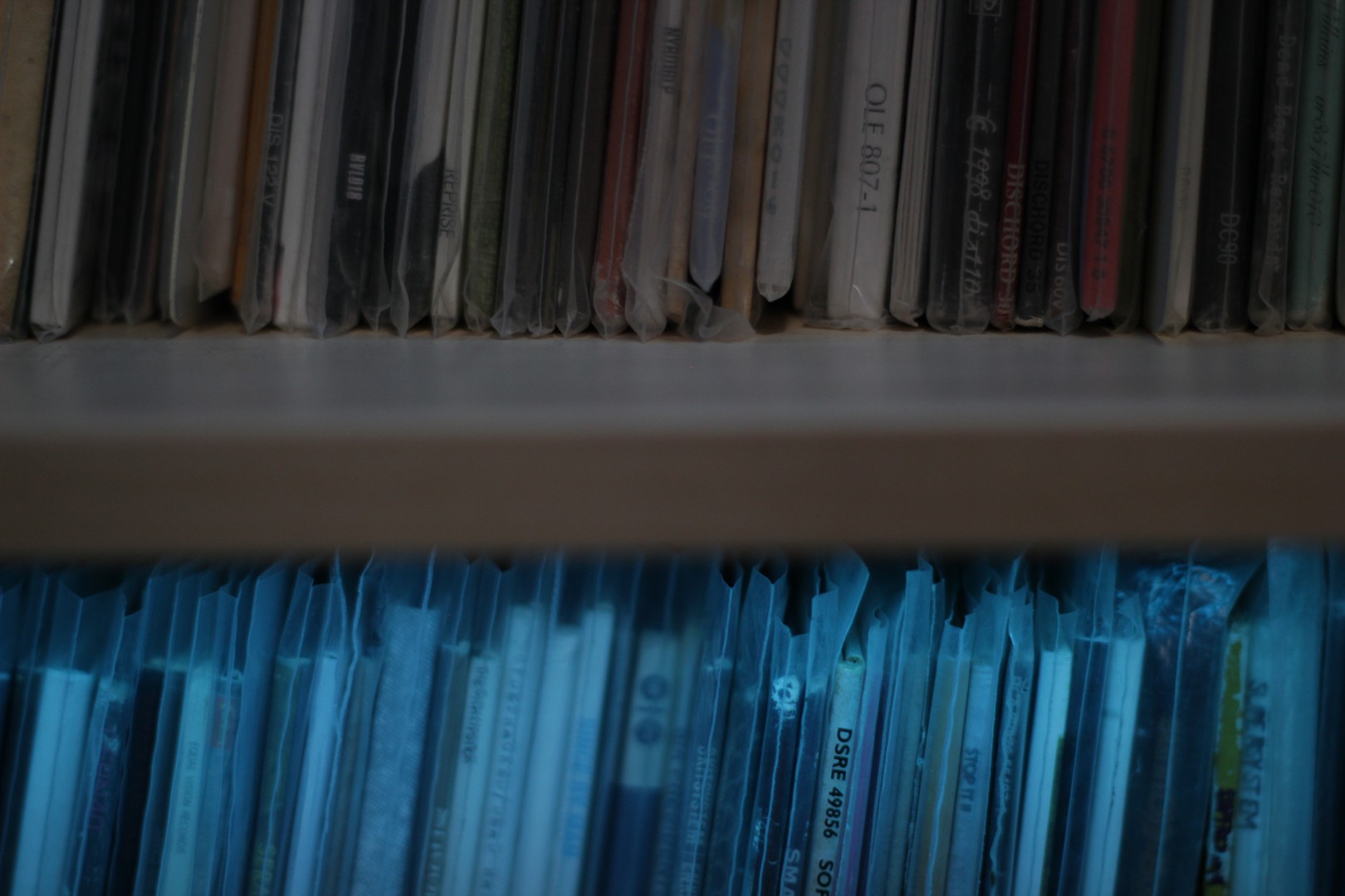
I tested each horizontal shelf individually, testing the power lead at each end of the strip (each individual shelf has a power feed at the beginning and end of the strip) before doing a full power up. Once everything was powered up, I booted up the Raspberry Pi 0 w that I had been using in the previous iteration of the shelf. The first 16 boxes lit up immediately with not problem, as those were the only ones that had been configured in the last version of the shelf (4x4 shelf = 16 boxes, new shelf is 5x5 = 25 boxes). I updated the Fadecandy config file to accommodate the new configuration of LEDs including introducing a second, entirely new, Fadecandy to the setup. After the config was updated, the shelf lit up like a charm.
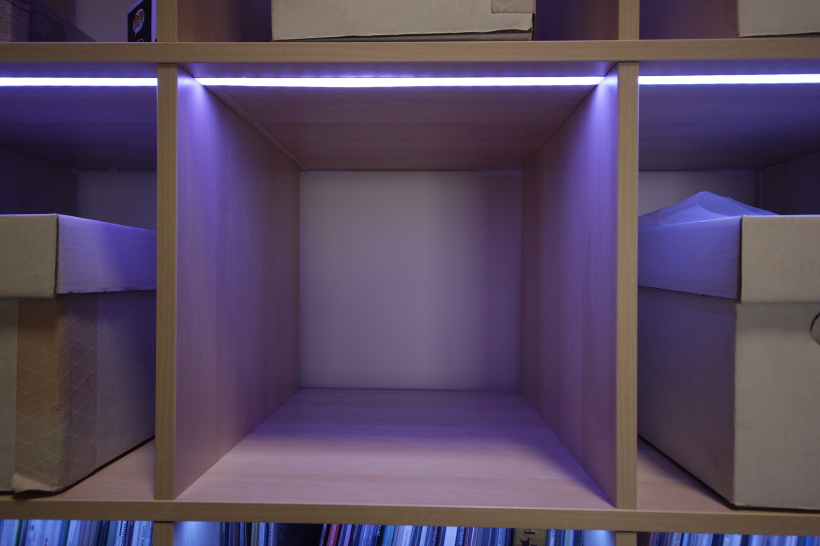
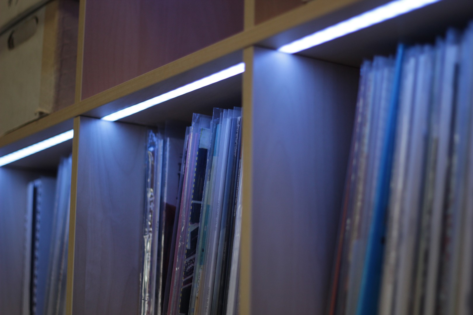
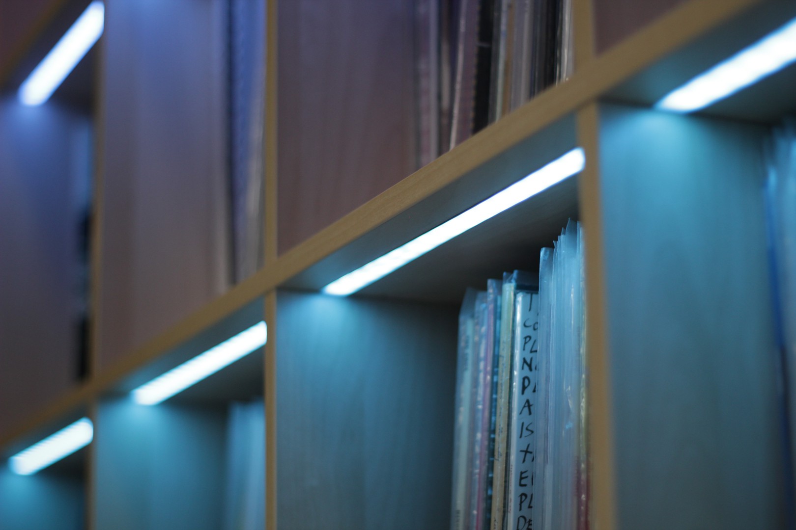
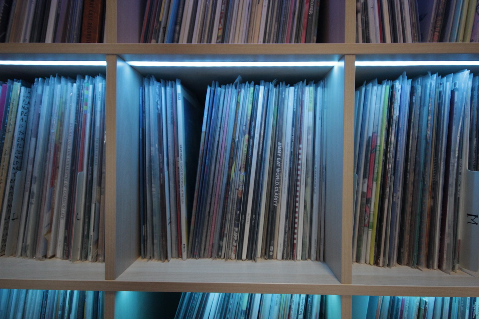
The following picture was the first full lighting of the shelf that occurred, plus it serves as a good example of how clean the wiring ended up.
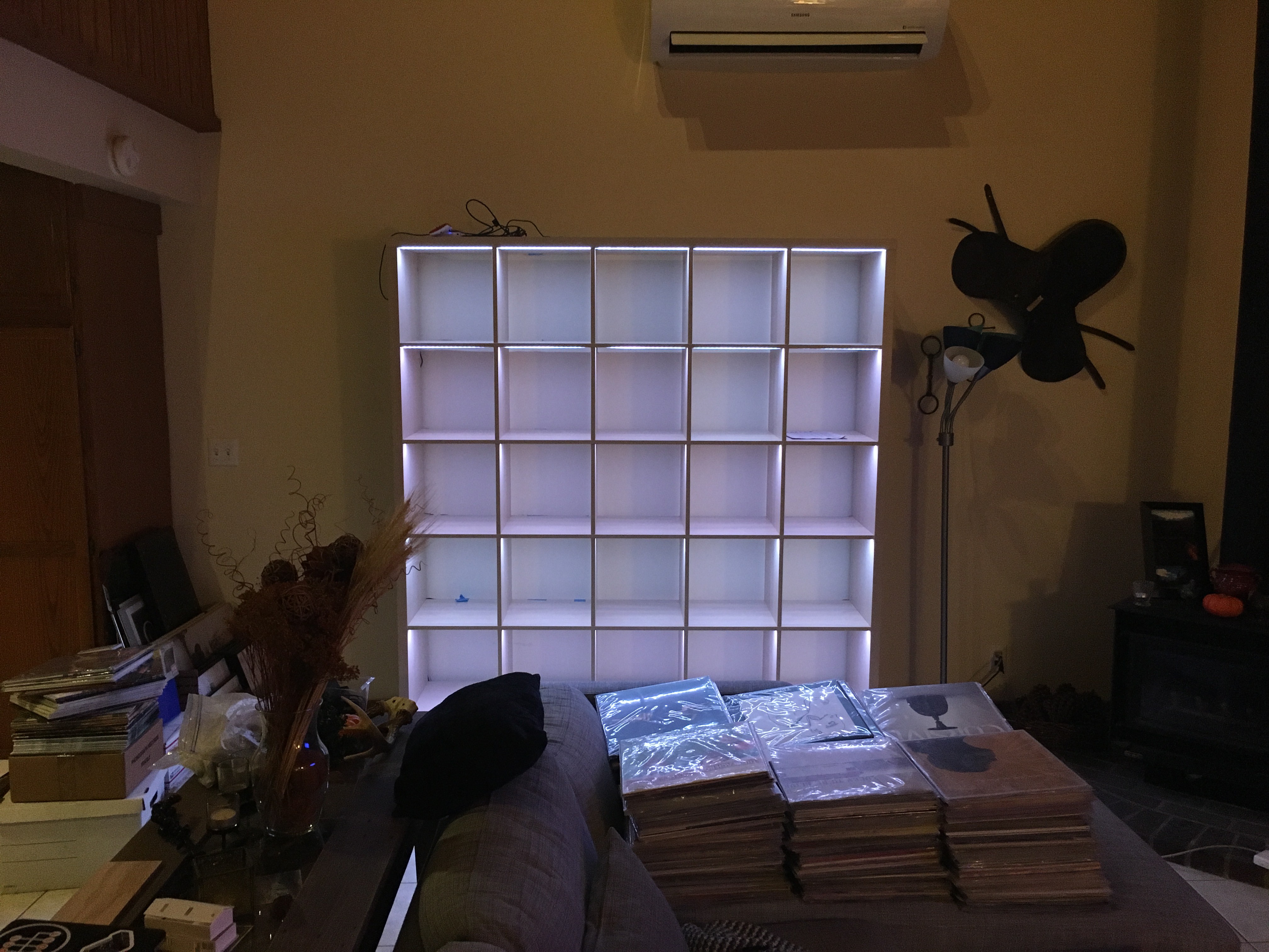
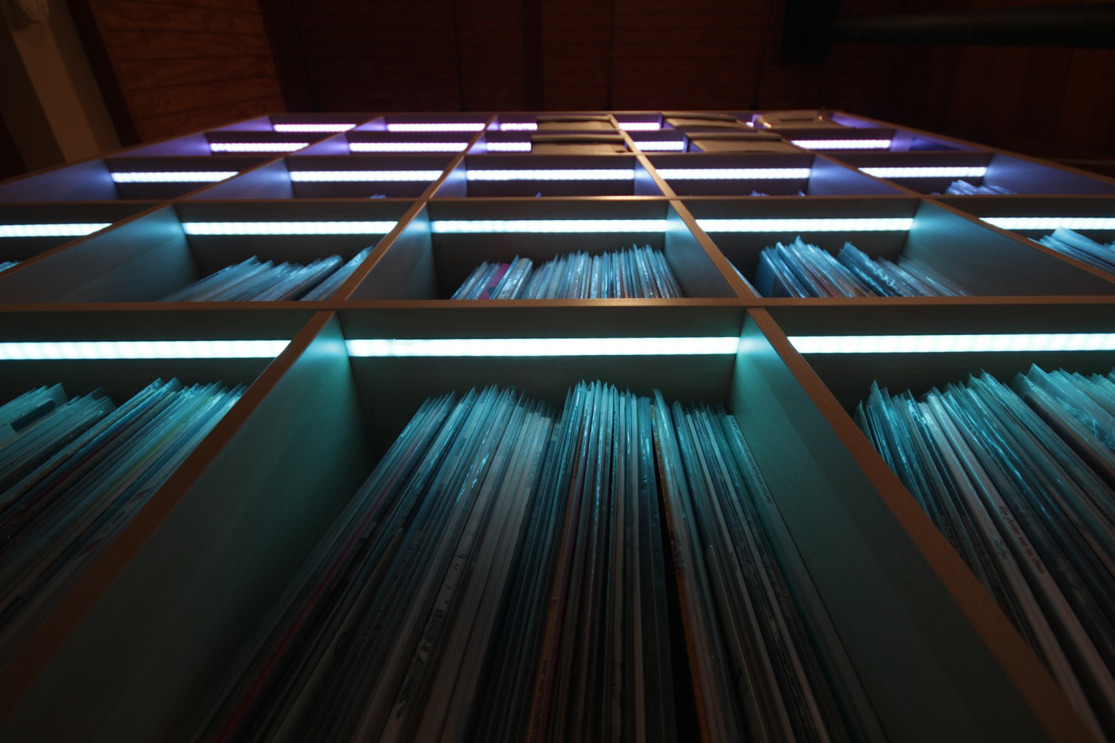
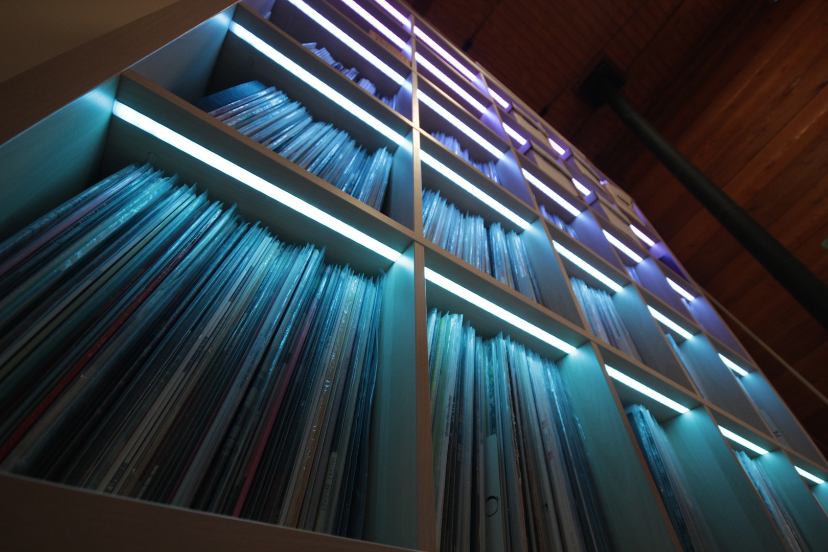
Glamour Shots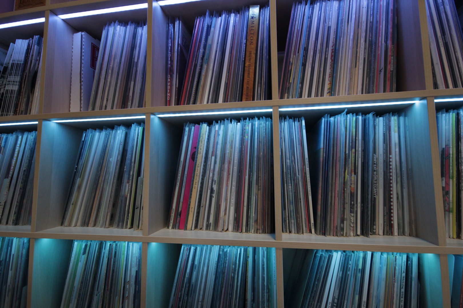


To Do List
The main item left on the list is to trim/clean up the wiring that terminates at the two Fadecandy boards. I would like to mount these as well as the Raspberry Pi in some sort of visually pleasing manner but I haven't figured that out all the way. I also have a lot of software improvements to work on but for now I thought it was a good place to stop and document the build thus far.
Discussions
Become a Hackaday.io Member
Create an account to leave a comment. Already have an account? Log In.