The next thing I want to tackle is bootstrapping, or as the EDSAC team would have called it, "loading the initial orders".
I haven't decided exactly what form the bootstrap device will take yet, but I'm assuming it will be some kind of parallel input device that interfaces in a similar way to the paper tape reader. So before going any further I decided to make some changes to the way I/O devices are handled so I can treat them in a more uniform way.
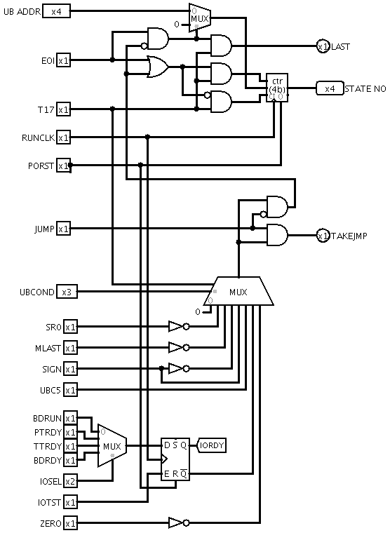
I/O condition testing
I didn't have any more branch condition inputs available, so I added an IOTST operation that samples one of four input conditions and latches it for branching on by a subsequent microinstruction. The conditions are assigned as follows:
PTRDY - data is available from the paper tape reader
TTRDY - teletype is ready to accept data
BDRDY - data is available from the boot device
BDRUN - boot device is running
TTRDY and PTRDY were previously connected directly to inputs of the branch condition multiplexer. One of those inputs is now called IORDY and is used to sense the condition latched by IOTST; the other is currently spare.
The condition to be tested by IOTST is selected by the IOSEL field, which again re-uses two bits from the UBRANCH field.
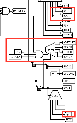
I/O control signals
On the outwards side, there is an IOSIG operation that produces one of four output pulses during the second half of T17, selected by IOSEL.
PTACK - acknowledge data from paper tape reader
TTOUT - signal teletype that data is available
BDACK - acknowledge data from boot device
BDSTART - start the boot device
Paper tape input
Input data from the paper tape is now read into the S register via the PIB, instead of having its own dedicated shift register.
Logisim Changes
Main circuit
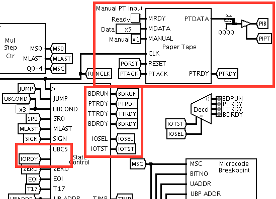 |  |
State Control ![]()
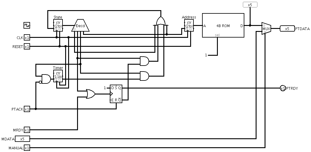
Paper tape simulation
For testing purposes, I put together a circuit that simulates a paper tape reader feeding in a few characters using the input device protocol. It incorporates a timer to slow down the input so that I can test whether the microcode correctly waits for the device to become ready.
New microcode for Input and Output instructions
# UBCOND values
BNIOT = 011  # I/O test false

# MISC values
IOSIG = 1010  # Generate I/O signal selected by IOSEL
IOTST = 0110  # Test I/O sense line selected by IOSEL

# PISEL values
PIPT = 10

# IOSEL values for IOSIG
PTACK = 10
TTOUT = 01
BDACK = 11

# IOSEL values for IOTST
BDRUN = 00
PTRDY = 10
TTRDY = 01
BDRDY = 11

# O - Output
   0 01001 0 0001 :  -   -   --  ---   -  --    -     -   --   -   -   -   -   -    -   IOTST   -   ---    TTRDY --  # Test TTY
   0 01001 0 0010 :  -   -   --  ---   -  --    -     -   --   -   -   -   -   -    -   ----    -   BNIOT  1000      # Loop until ready
   0 01001 0 0011 : SHS EOI  --  ---   -  --    -     -   --   -   -   -   -   -    -   IOSIG   -   ---    TTOUT --  # Read memory into S and signal TTY

# I - Input
   0 01000 0 0001 :  -   -   --  ---   -  --    -     -   --   -   -   -   -   -    -   IOTST   -   ---    PTRDY --  # Test paper tape
   0 01000 0 0010 :  -   -   --  ---   -  --    -     -   --   -   -   -   -   -    -   ----    -   BNIOT  1000      # Loop until ready
   0 01000 0 0011 :  -   -   --  ---   -  --    -     -   --   -   -   -   -   -    -   PLS     -   ---    PIPT  --  # Load paper tape data into S
   0 01000 0 0100 : SHS EOI  --  XSR   -  --    -    WMEM --   -   -   -   -   -    -   IOSIG   -   ---    PTACK --  # Write S to memory and ack paper tape
Discussions
Become a Hackaday.io Member
Create an account to leave a comment. Already have an account? Log In.