 Anthony Kouttron
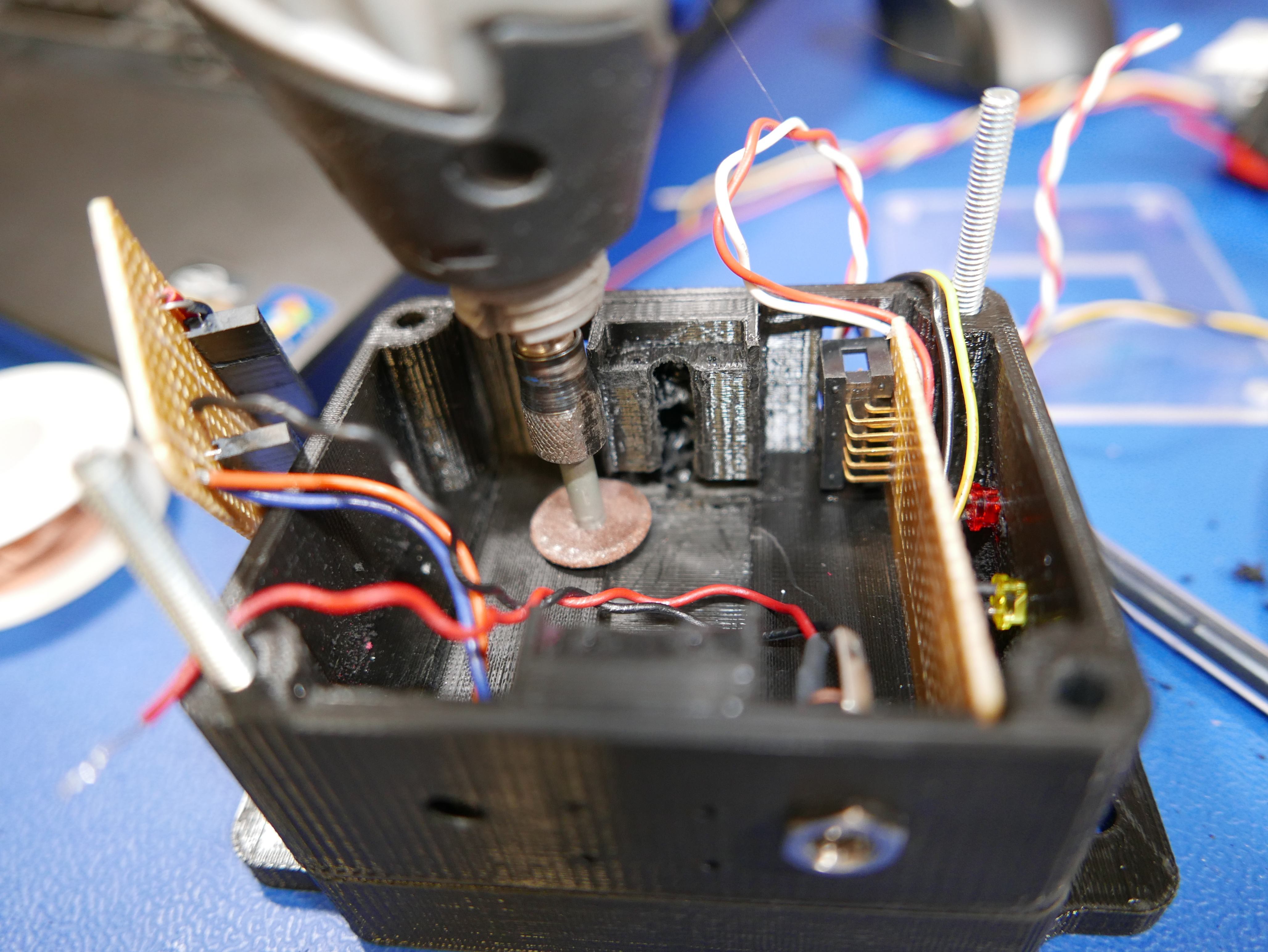
Time of Flight (TOF) sensors are quite useful in measuring distances between objects and a point of reference. Instead of measuring distances using an ultrasonic sensor, infrared proximity sensor or computer vision techniques, this tiny laser source and emitter based system measures distances based on the speed of light. These sensors are becoming more accurate, higher resolution and more affordable for use in the maker community. After a bit of searching, I did not come across a stand alone TOF sensor module for remote camera car operation. I decided to build my own dedicated TOF sensor unit that can be attached to a camera car with just (4) AA batteries and a few bolts. The goal is to produce a module that can be used alongside other sensory equipment to adequately analyze objects and rough terrain in the surrounding environment that would produce to great of an obstacle for the camera car suspension to dampen.
There are several all-in-one TOF laser-emitter packages on the market, such as the STMicroelectronics VL53L0X, VL53L1X and VL6180X, the Texas Instruments OPT3, OPT8 and OPT9 Series, the Chirp Microsystems’ CH-101 and CH-201 and the Heptagon OLIVIA line of TOF sensors. I decided upon an STMicroelectronics VL53L0X unit because it seems to be the most commonly available TOF unit on the market.
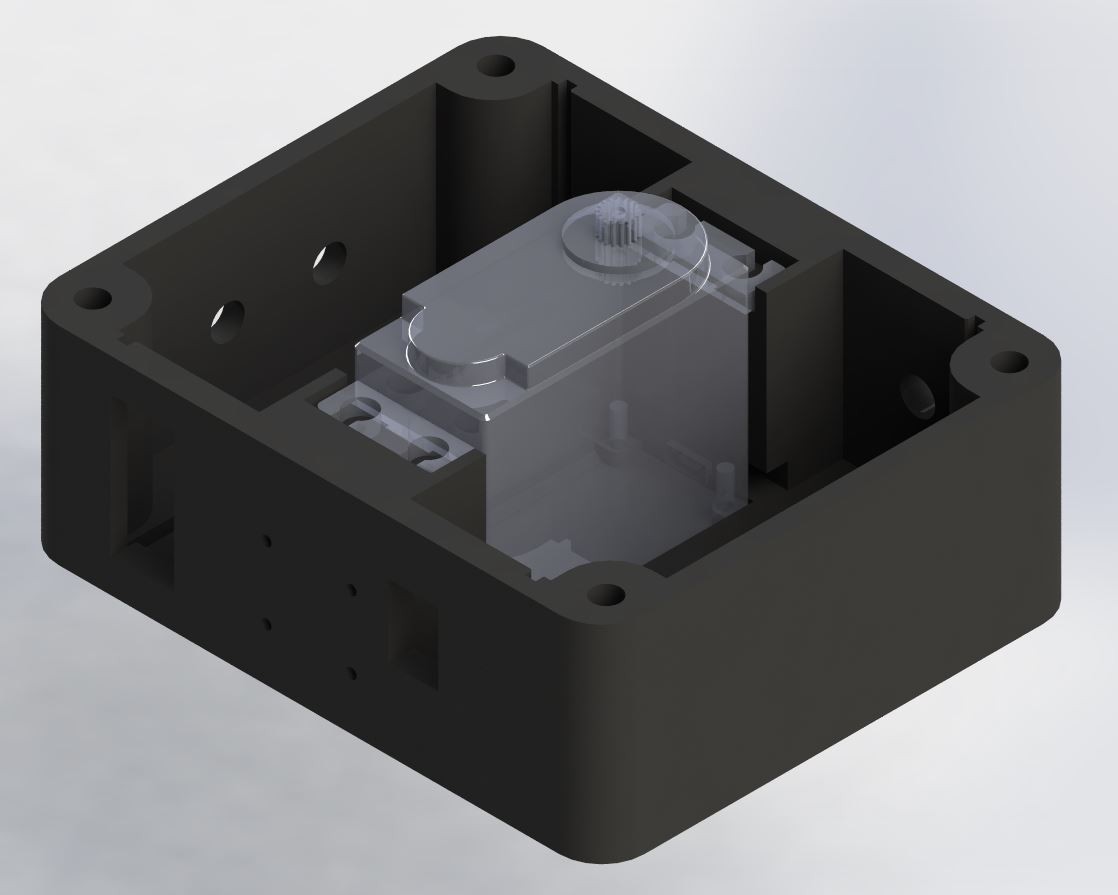
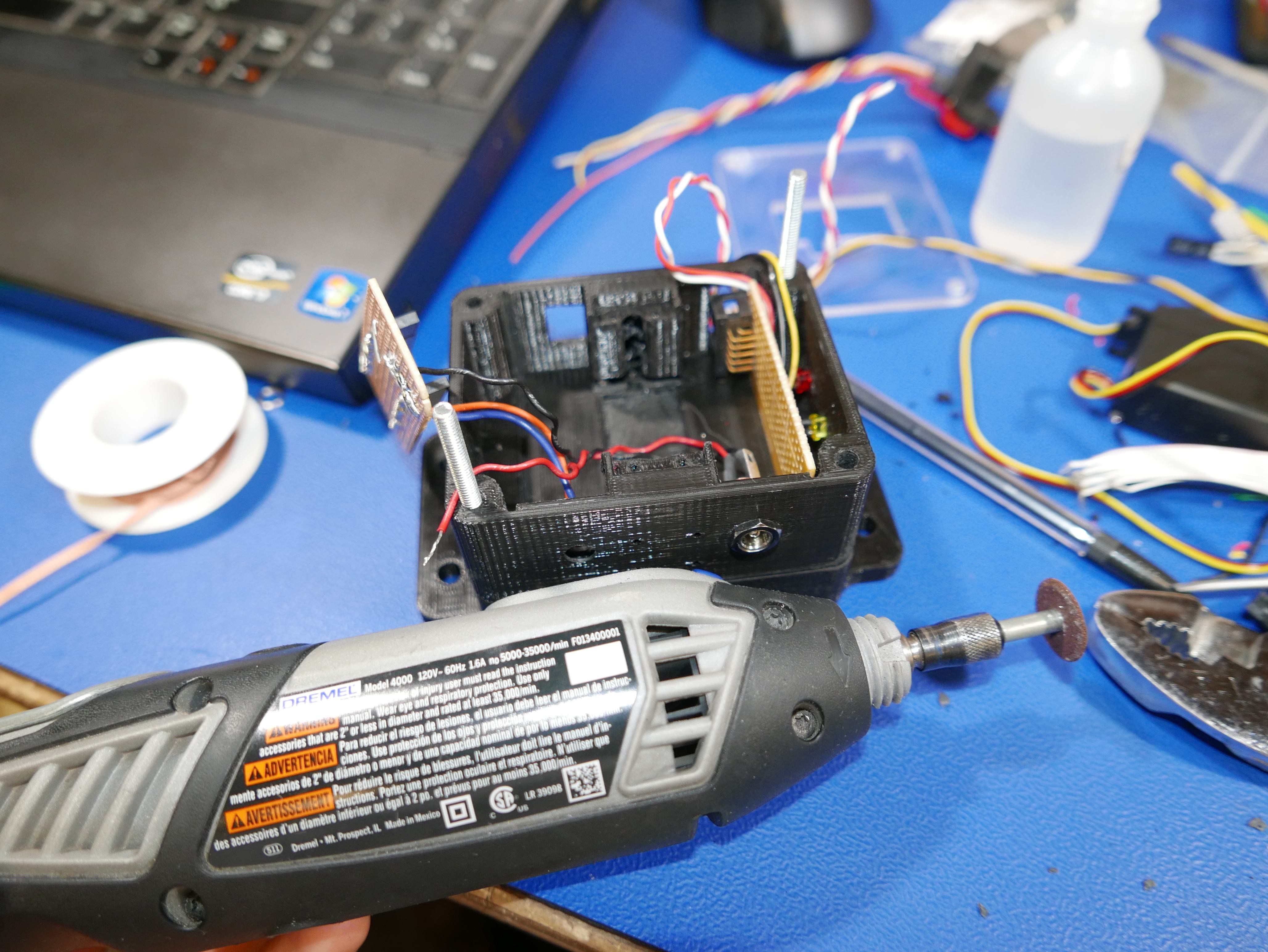
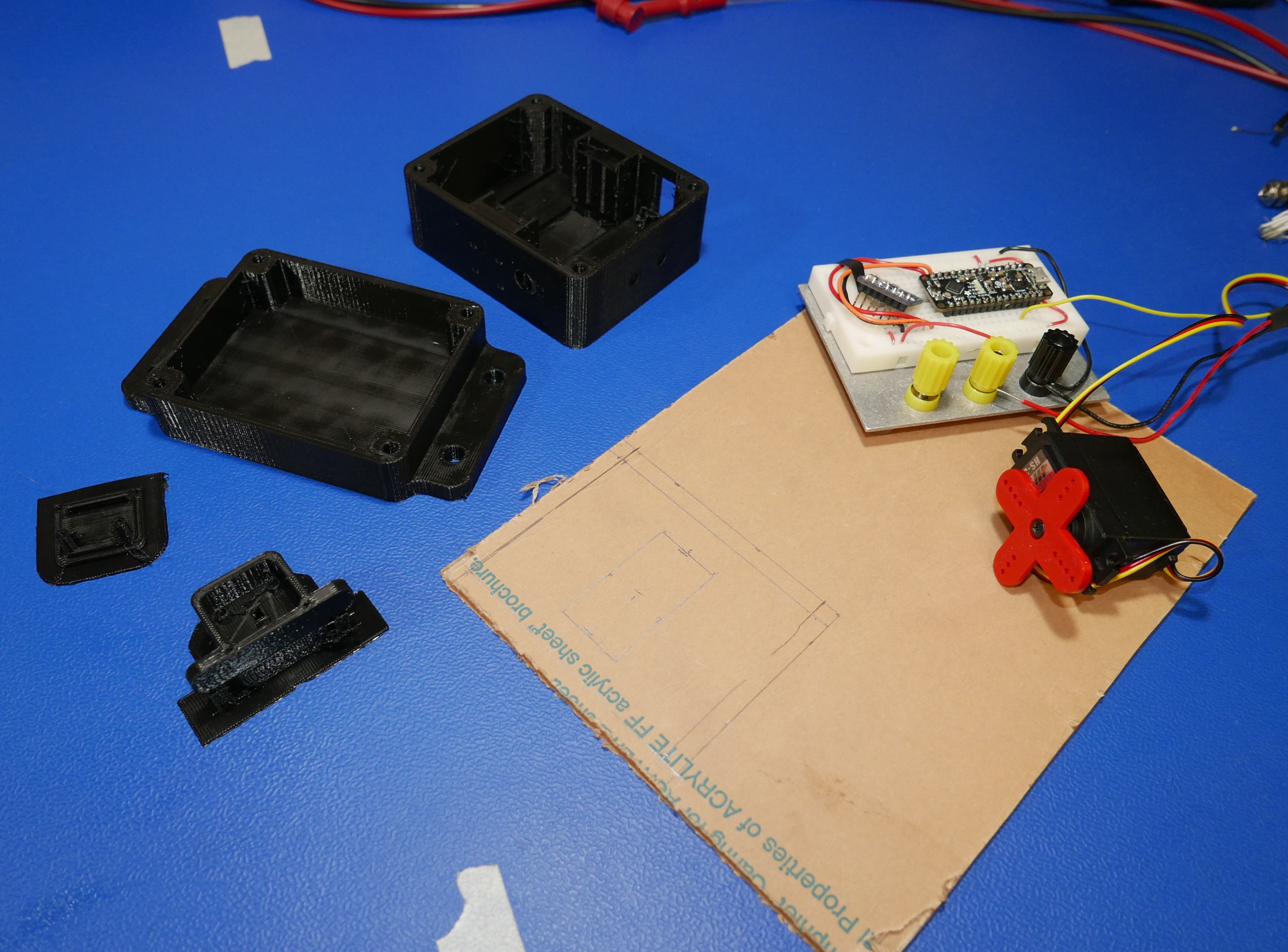
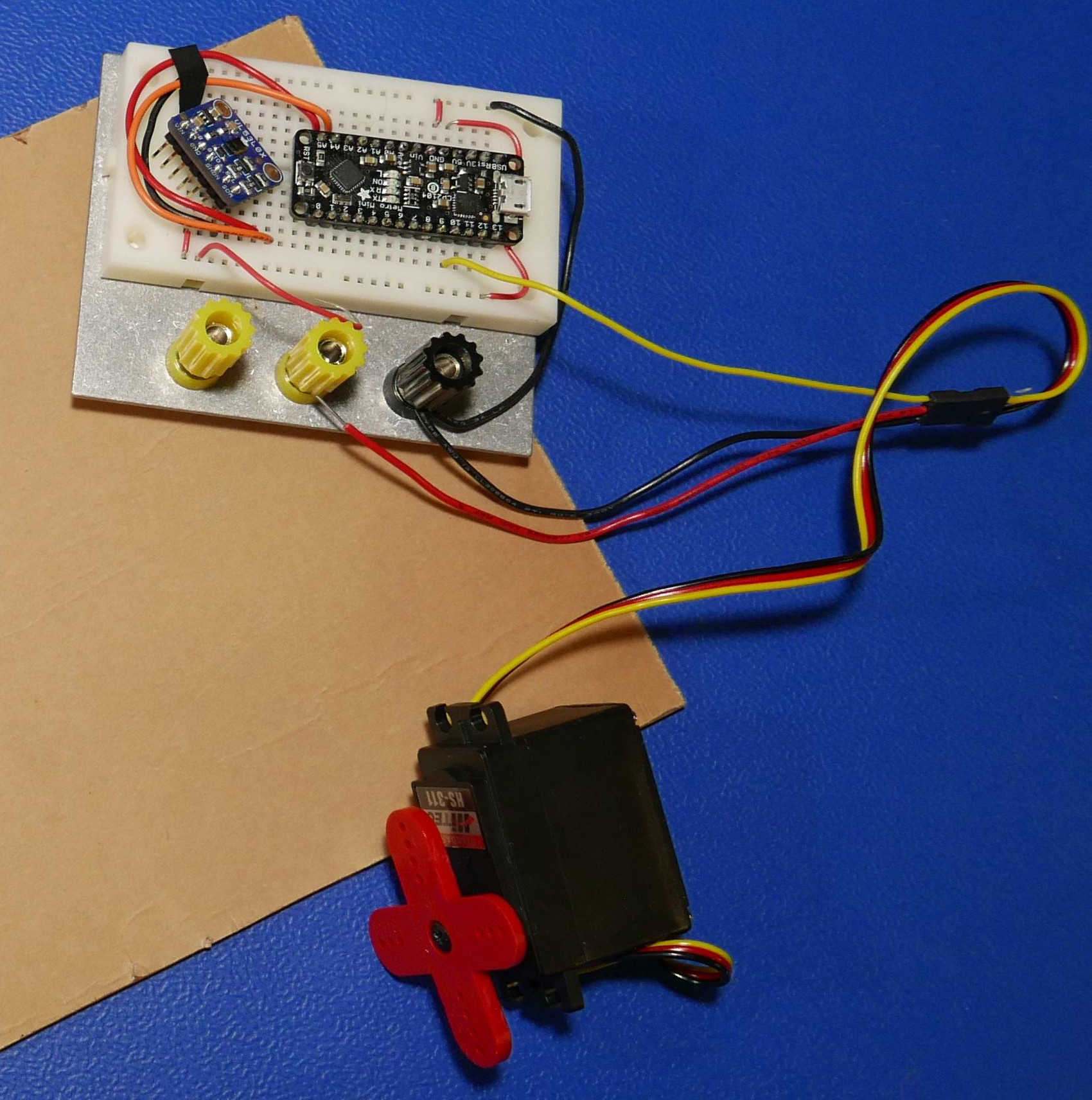
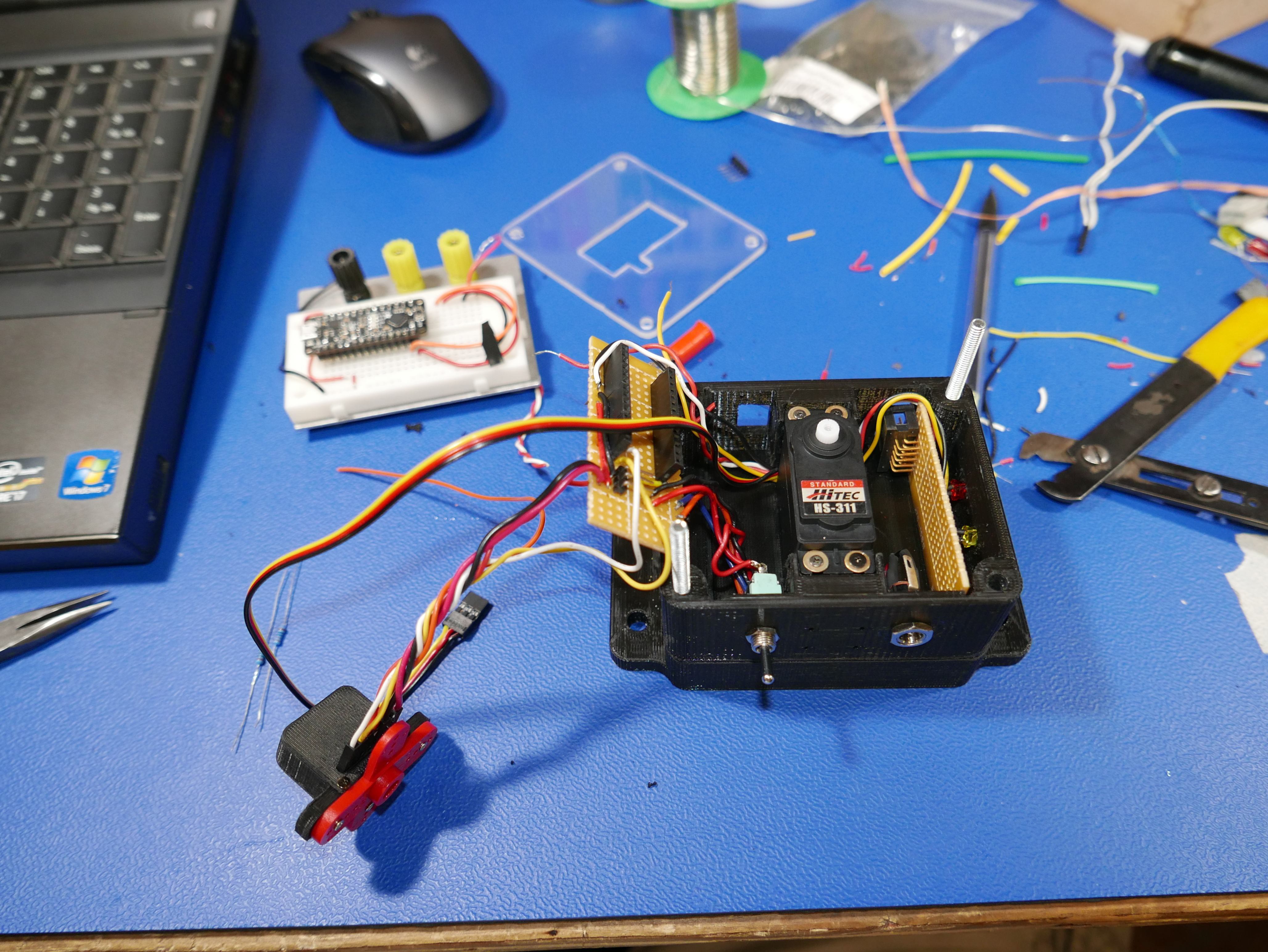
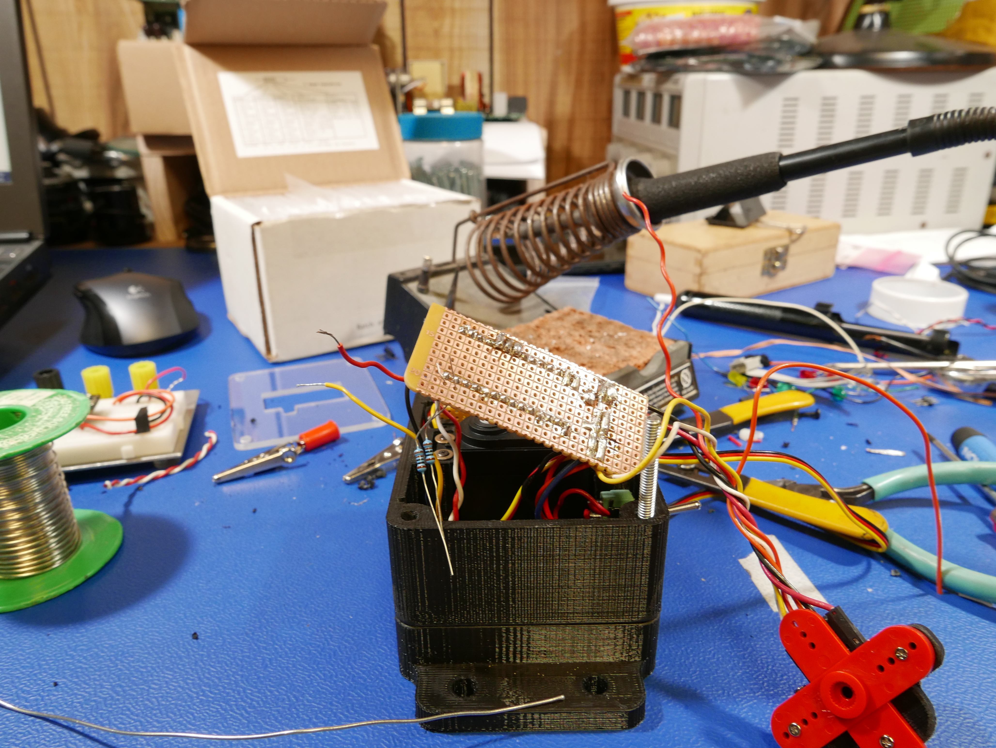
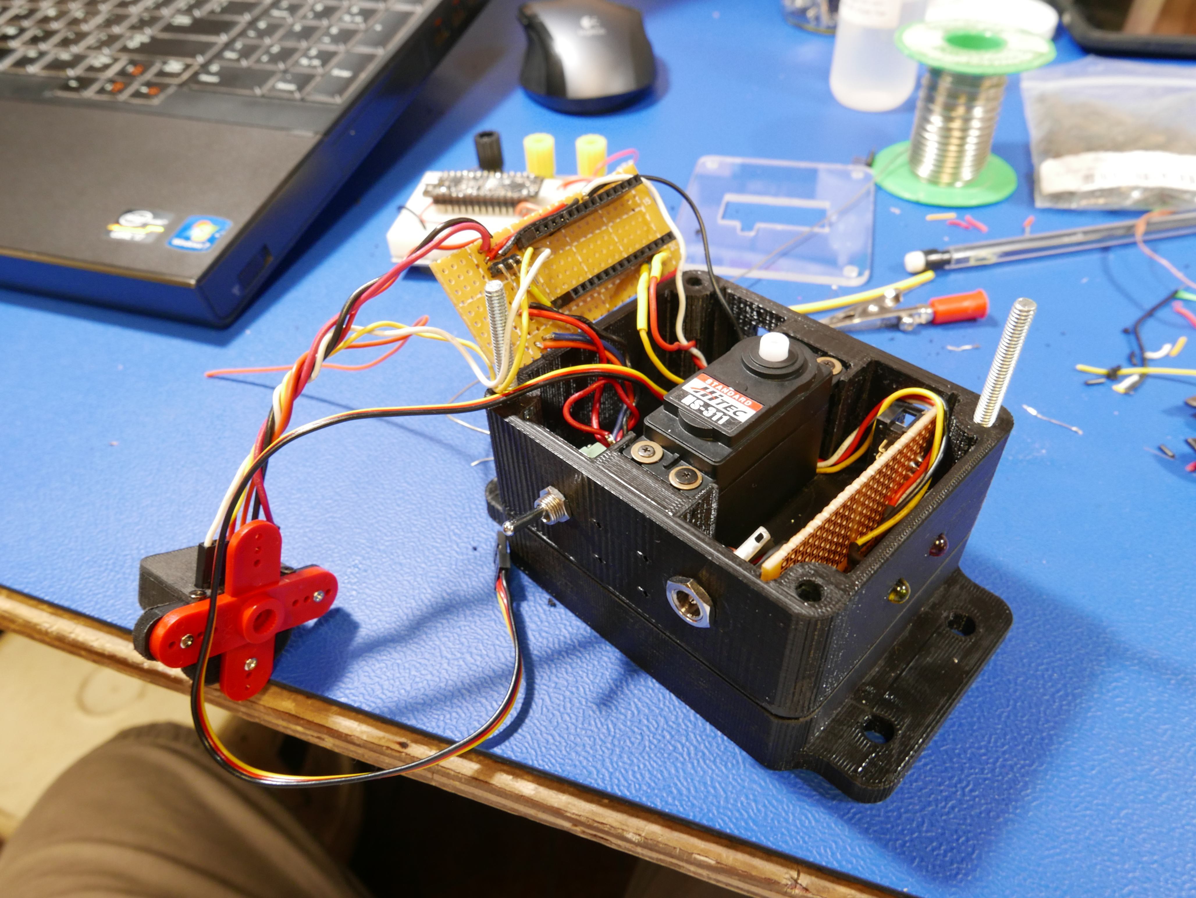
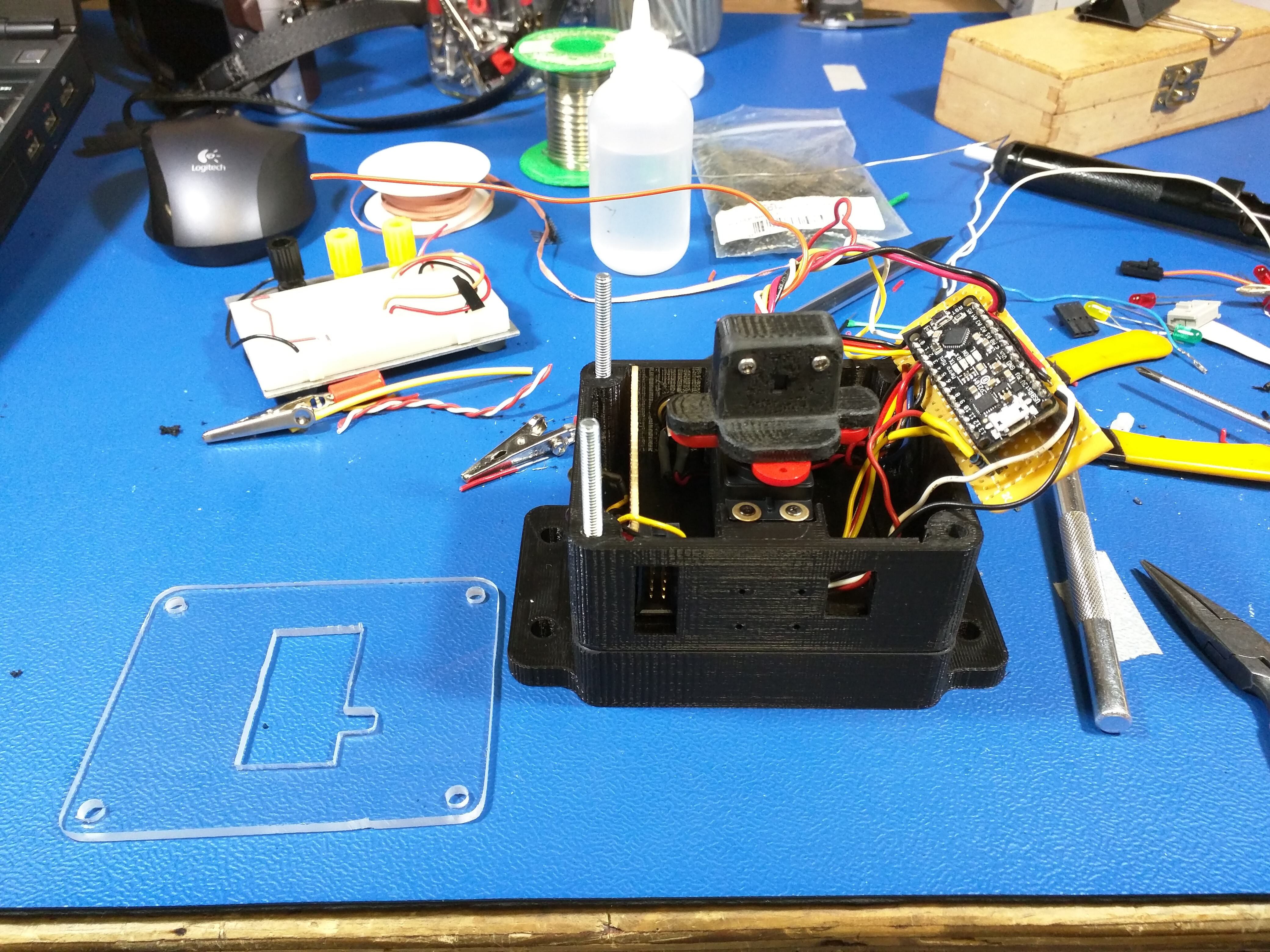
To make this project as easily repeatable as possible, I decided to use parts that were as commonly available as possible. I took a tip to a microcenter and picked up the Adafruit metro micro, VL53L0X sensor unit and a HS-311 servo motor. The total BOM of this project is about $35.
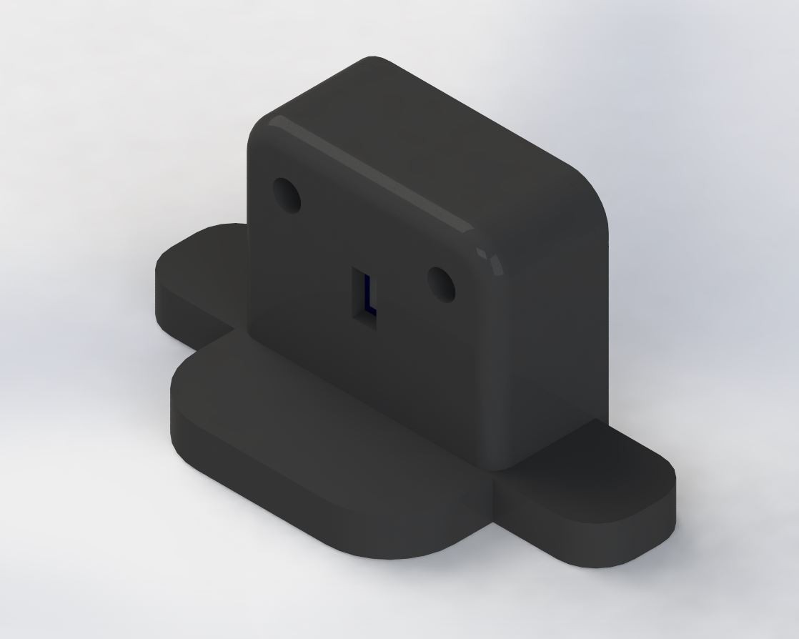
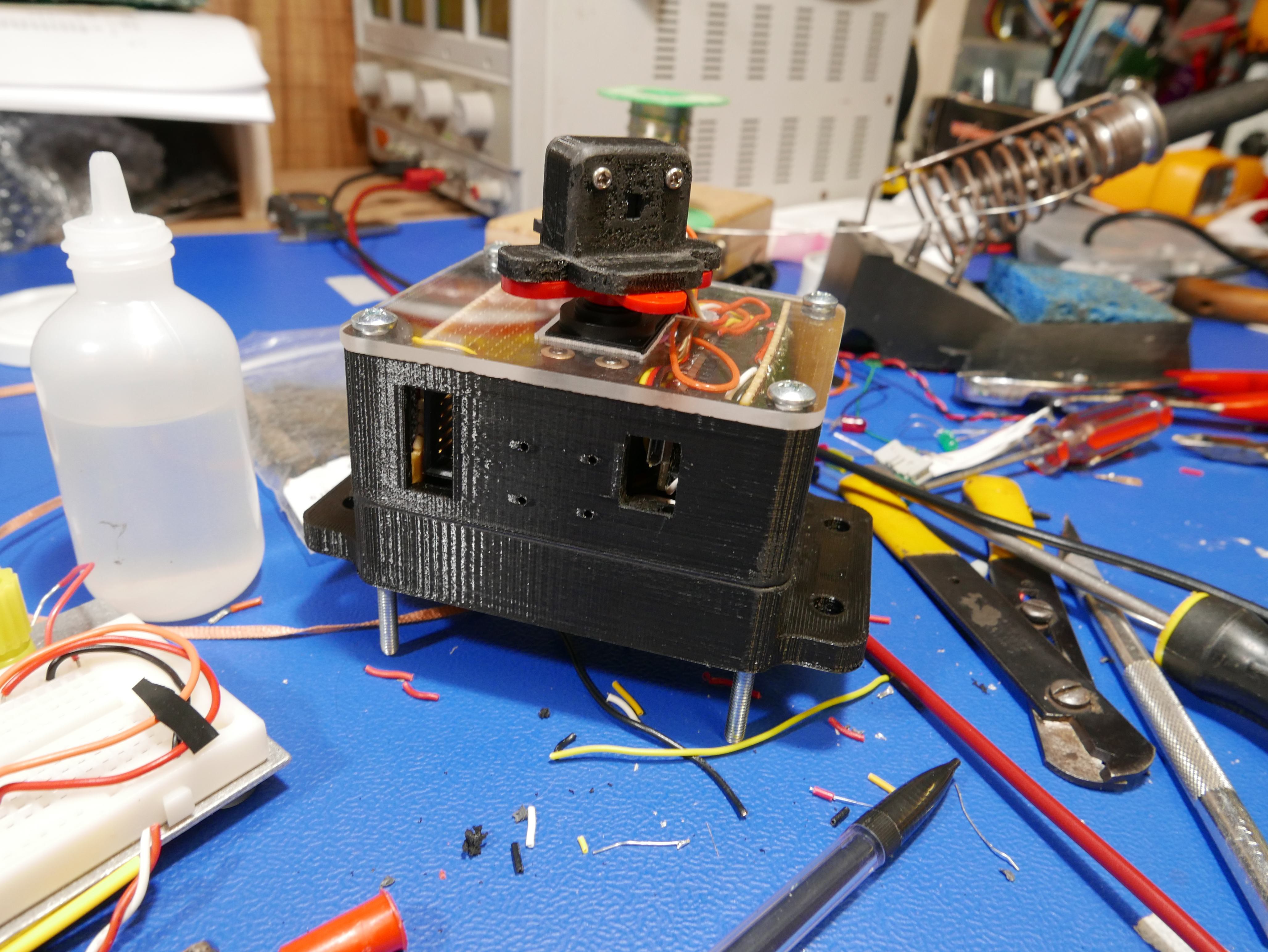
The ideal module for my application would look something like this:
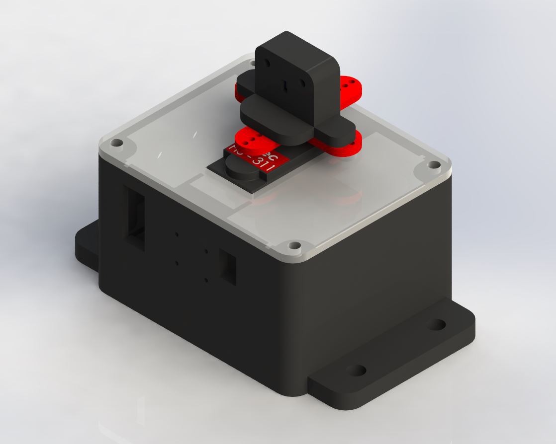
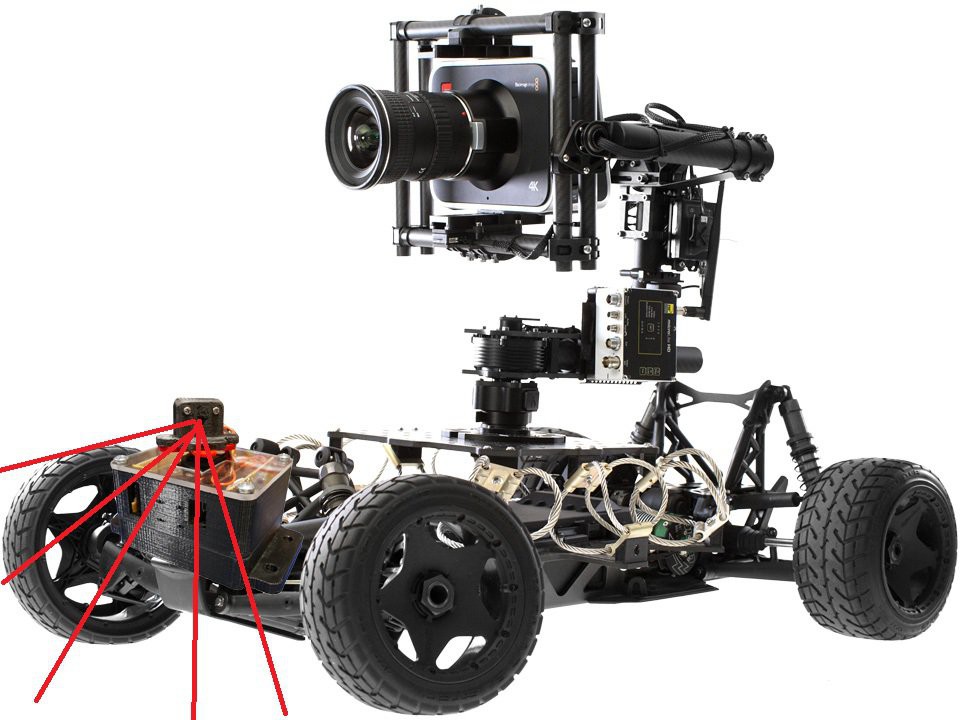
This is how I am imagining using the module. My photoshop skills are not the best, but there is limited space on the camera car for additional modules, as most of the body is designated for electro-mechanical dampening systems.

 j
j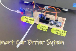
 HYuiii
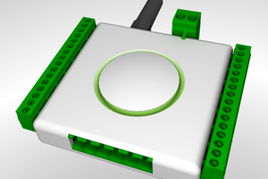
 Laurence
 Frank.Muenzner