Salah Missri
All of our boards were drawn using KiCad and are released under the CC-BY 4.0 license.
Our software is released under MIT license, additionally we have ChibiOS RTOS/HAL (GPLv3 license) and UAVCAN (MIT license) as core dependencies.
The CAN bootloader is released under BSD 2-clause license.
Motor board
The motor board is a small board (31x16mm) with a dedicated STM32F3 microcontroller that is at the core of all our robots since 2015.
We have been using it to control DC motors, motor pumps, and RC servos.
Here are its main features:
- CAN interface with communication over UAVCAN for parameter/gain setting, setpoint sending, and feedback streaming.
- CAN bootloader for easy firmware update over the bus.
- Control a single DC motor with current sensing, allowing cascaded PID control (torque, velocity, and position).
- H-bridge to drive the motor bidirectionally that supports driving a motor with up to 16.8V @ 6.6A continuously.
- Quadrature encoder interface for motor (5V tolerant).
- Secondary quadrature encoder interface (5V tolerant) (eg. for separate odometry wheels).
- Analog input for RC-servo control.
- Digital input for indexing, allows us to determine a reference location on a given axis that can be used for absolute positioning.
- Runs on 3 or 4 cell LiPo/LiFe batteries.
- SWD connector for flashing and debugging, with UART exposed on the same connector.
- Costs < 35 USD in components.
Links
- Hardware including KiCad files, the schematics in PDF, and gerber files.
- Software using ChibiOS RTOS/HAL, and UAVCAN for communication.

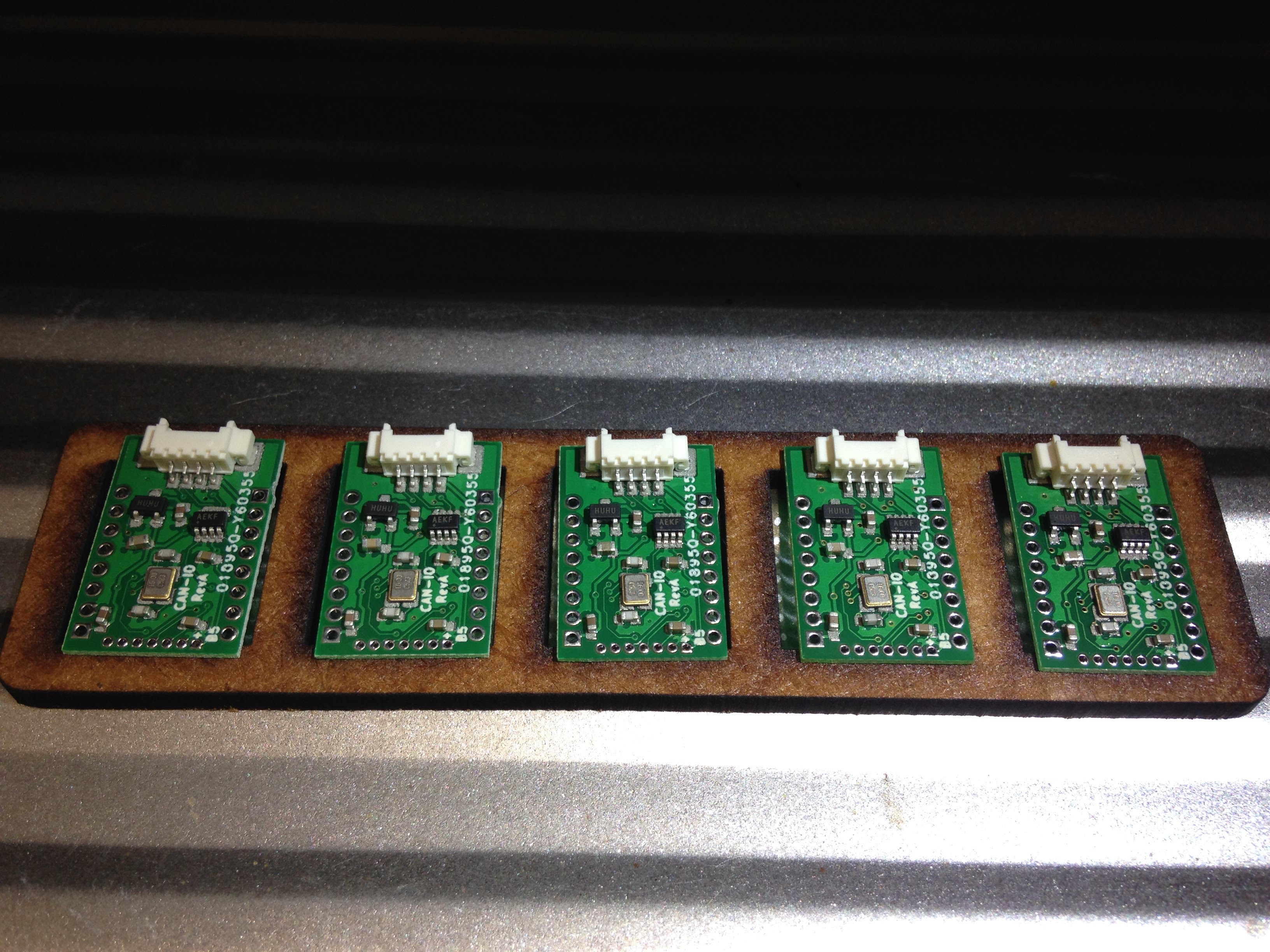
IO board
The IO board is a 23x15mm board with a dedicated STM32F3 microcontroller and the following features:
- CAN interface with communication over UAVCAN for IO control (read / write).
- CAN bootloader for easy firmware update over the bus.
- 11 GPIOs exposing:
- Digital outputs, including timer channels for PWM,
- Digital inputs, including timer channels for pulse counting,
- Analog inputs (ADC).
- Communication busses such as I²C and SPI.
- Molex Picoblade connectors for wiring CAN in daisy chain.- SWD connector for flashing and debugging, with UART exposed on the same connector.
- Costs < 10 USD in components.
Current application software allows a general purpose usage exposing basic I/O control over UAVCAN: PWM output and digital inputs.
Links
- Hardware including KiCad files, the schematics in PDF, and gerber files.
- Software using ChibiOS RTOS/HAL, and UAVCAN for communication.

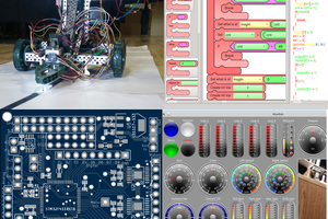
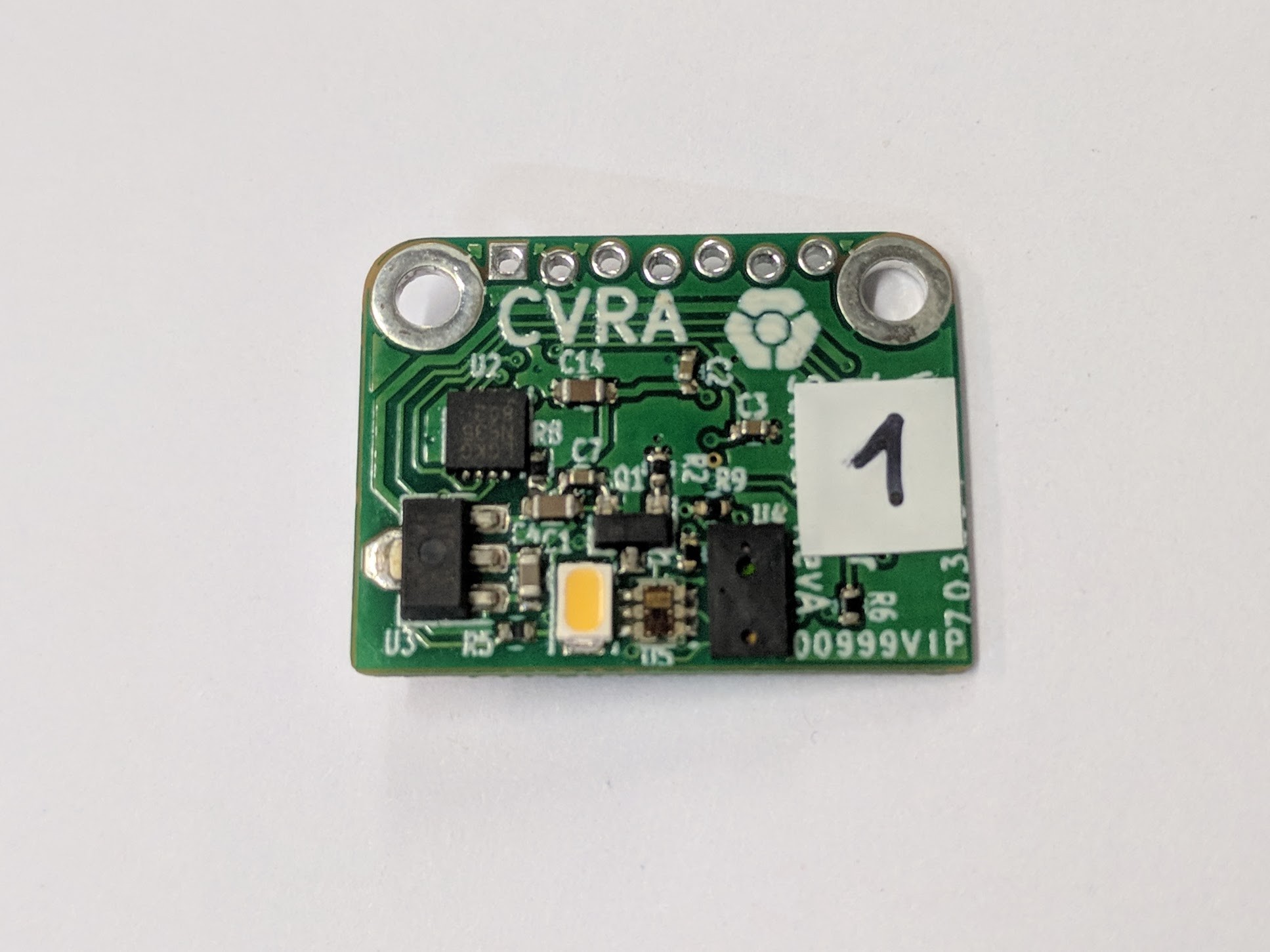
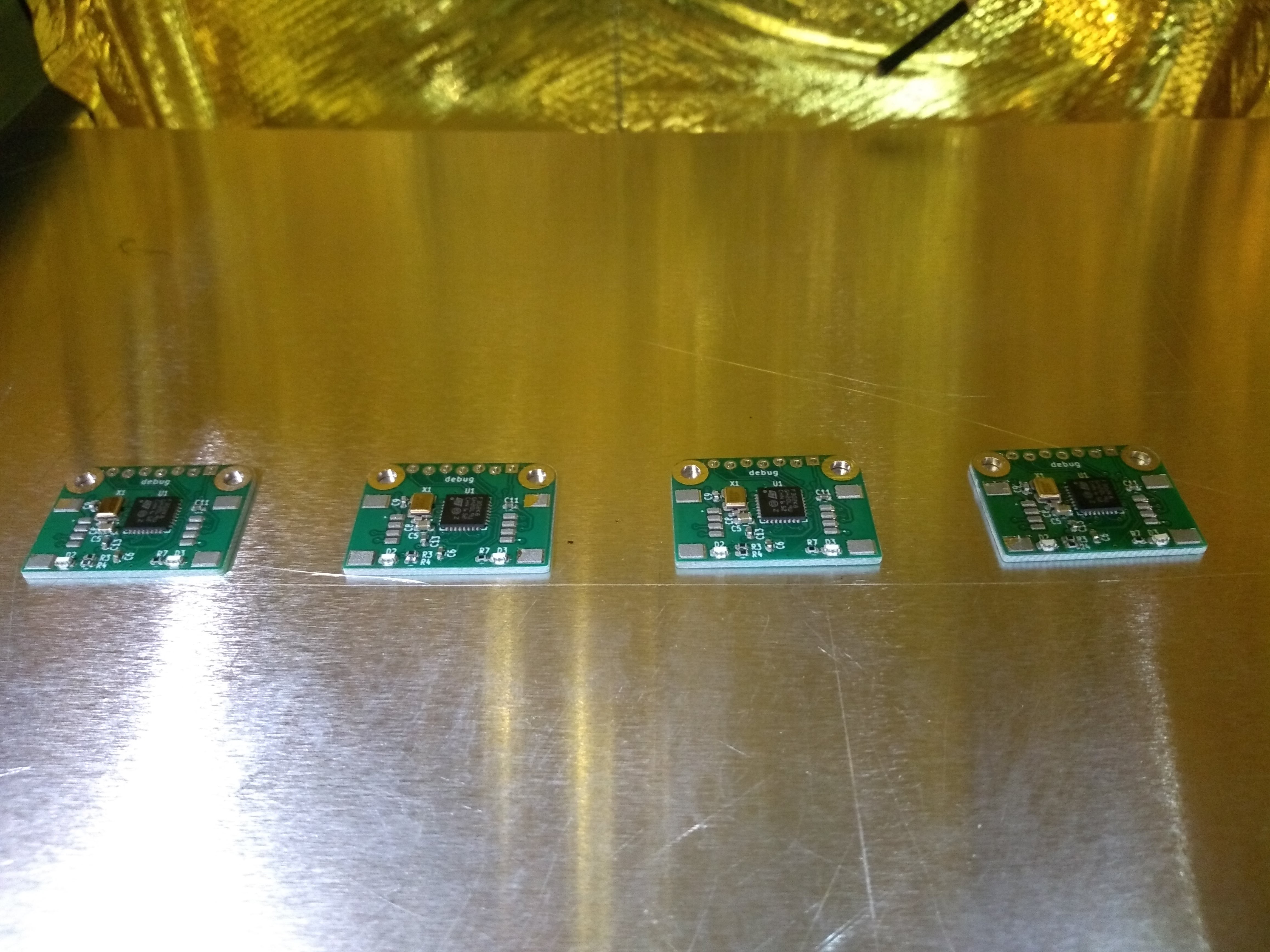
Sensor board
The sensor board is a 23x17mm with a dedicated STM32F3 microcontroller and the following features:
- CAN interface over which sensor data are streamed over UAVCAN.
- CAN bootloader for easy firmware update over the bus.
- Distance time-of-flight sensor (VL6180X) can measure distances from 10mm to 100mm with 1mm resolution.
- RGB Color sensor (TCS34725) with external illumination using a white LED
- Molex Picoblade connection for wiring CAN in daisy chain.
- SWD connector for flashing and debugging, with UART exposed on the same connector.
- 2x M2 holes for mounting
- Costs < 25 USD in components.
Current application software only supports the distance sensor.
Color sensor support is work in progress.
Links
- Hardware including KiCad files, the schematics in PDF, and gerber files.
- Software using ChibiOS RTOS/HAL, and UAVCAN for communication.
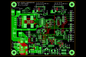
Beacon board
The Beacon board is a 42x30mm with a dedicated STM32F4 microcontroller and the following features:
- CAN interface with communication over UAVCAN.
- CAN bootloader for easy firmware update over the bus.
- An Ultra-Wide Band (UWB) module from Decawave for communication and beacon to beacon distance measurement
- Molex Picoblade connectors for wiring CAN in daisy chain.
- Micro USB connector for debugging and flashing via DFU.
- SWD connector for flashing...

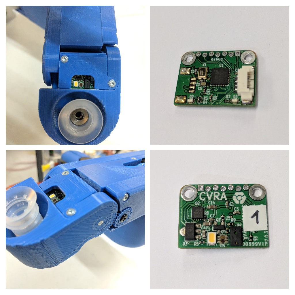
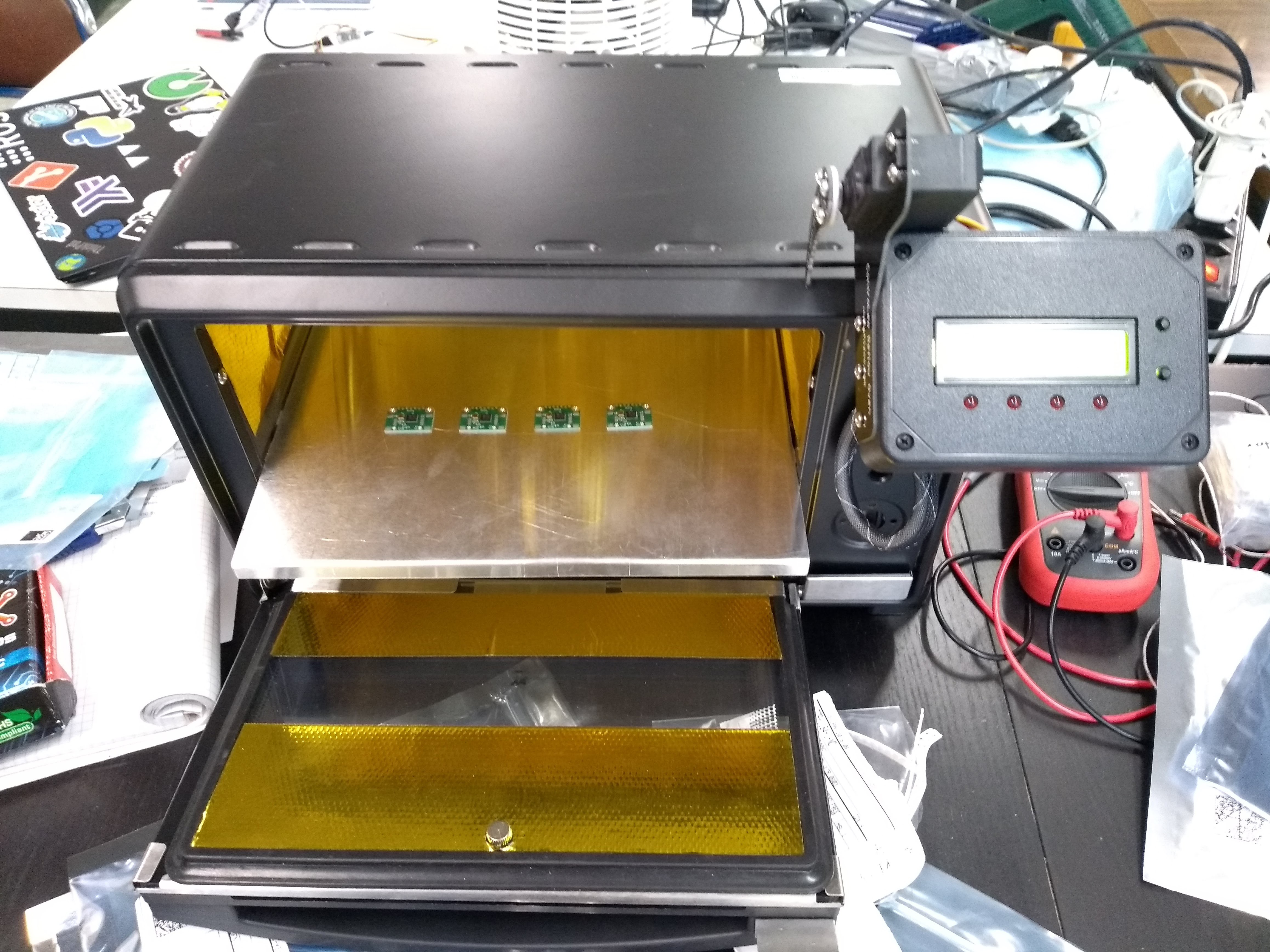
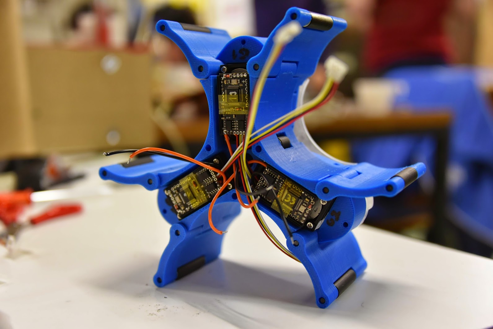
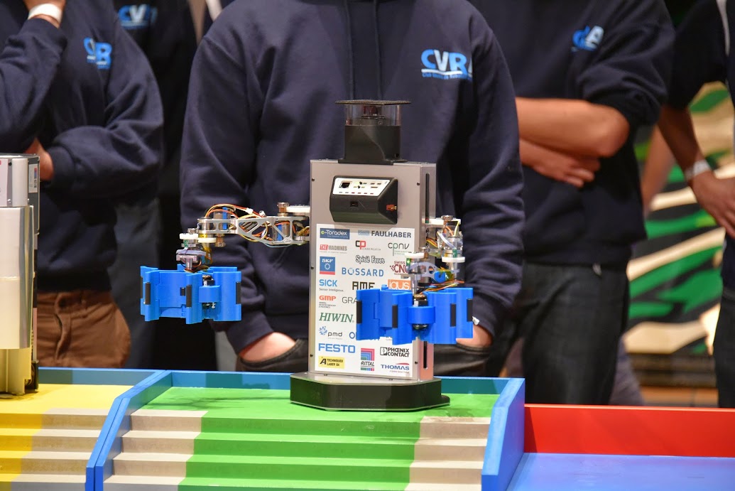

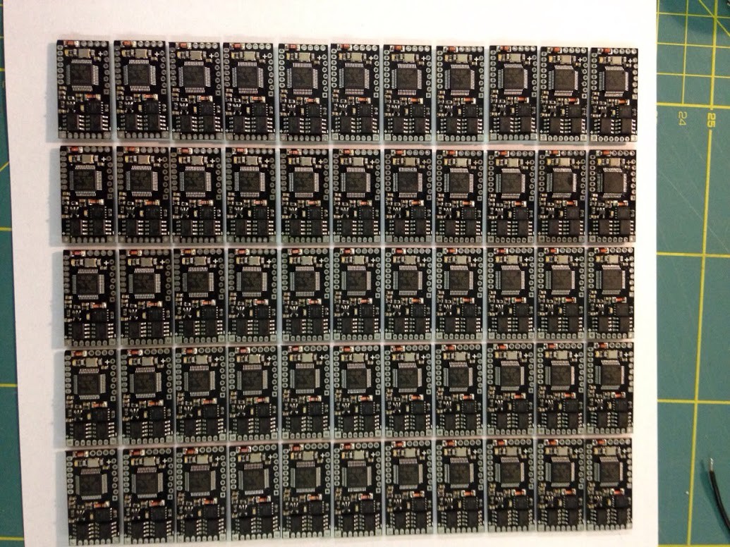
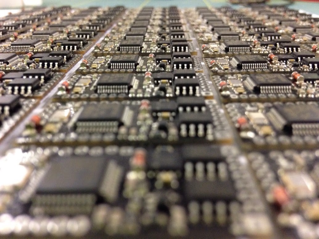
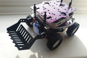
 All 60 boards are done. Time to build robots!
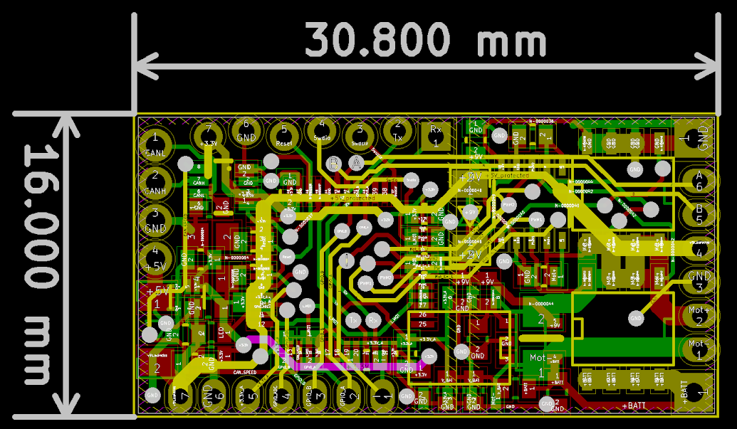
 Bharbour
 Samuk
Samuk