 Rory
RoryDesign Criteria
- Cheap – Only one planned to use.
- Reliable – I had over 500 pairs of spot welds to make
- Easy and quick to make - ideally using parts I had to hand
- Relatively Safe – No high voltages floating about
Introduction
As part of my electric mountain bike project I needed a large lithium battery. Not finding anything in my budget I decided to make a 18650 battery pack to my specifications.
I needed to be able to spot weld nickel strip to the 18650 cell terminals. 18650 spot welders are widely available on the net and probably worth the investment if you have the demand for it. However, I only planned to build one battery pack, so I made my own spot welder.
A brief search of other people’s projects revealed many microwave oven transformer-based devices. This seemed complex and a bit dangerous to me. I didn’t have a microwave oven I was willing to sacrifice. I did have a perfectly good high current source in my car that was sitting around doing nothing most of the time. Would it be possible to use a car battery with a timed switching circuit for spot welding?
A quick YouTube search found darkkevind’s channel. In this video in particular https://youtu.be/o1NFbchHeM8 he demonstrates his spot welder. His device is a standard car battery connected to a motorbike starter motor solenoid. The solenoid is triggered by a push button which switches power to two welding electrodes made from copper nails. His design worked well but I felt I could build on it to make a more reliable system.
Build
My design features a DELCO 130493 (pattern part) starter solenoid as the current switch. I liked the layout of the terminals which could be linked nicely to an ‘offset’ battery terminal clamp. The bracketry also allowed the electronics enclosure to be mounted neatly. All items are very low cost.
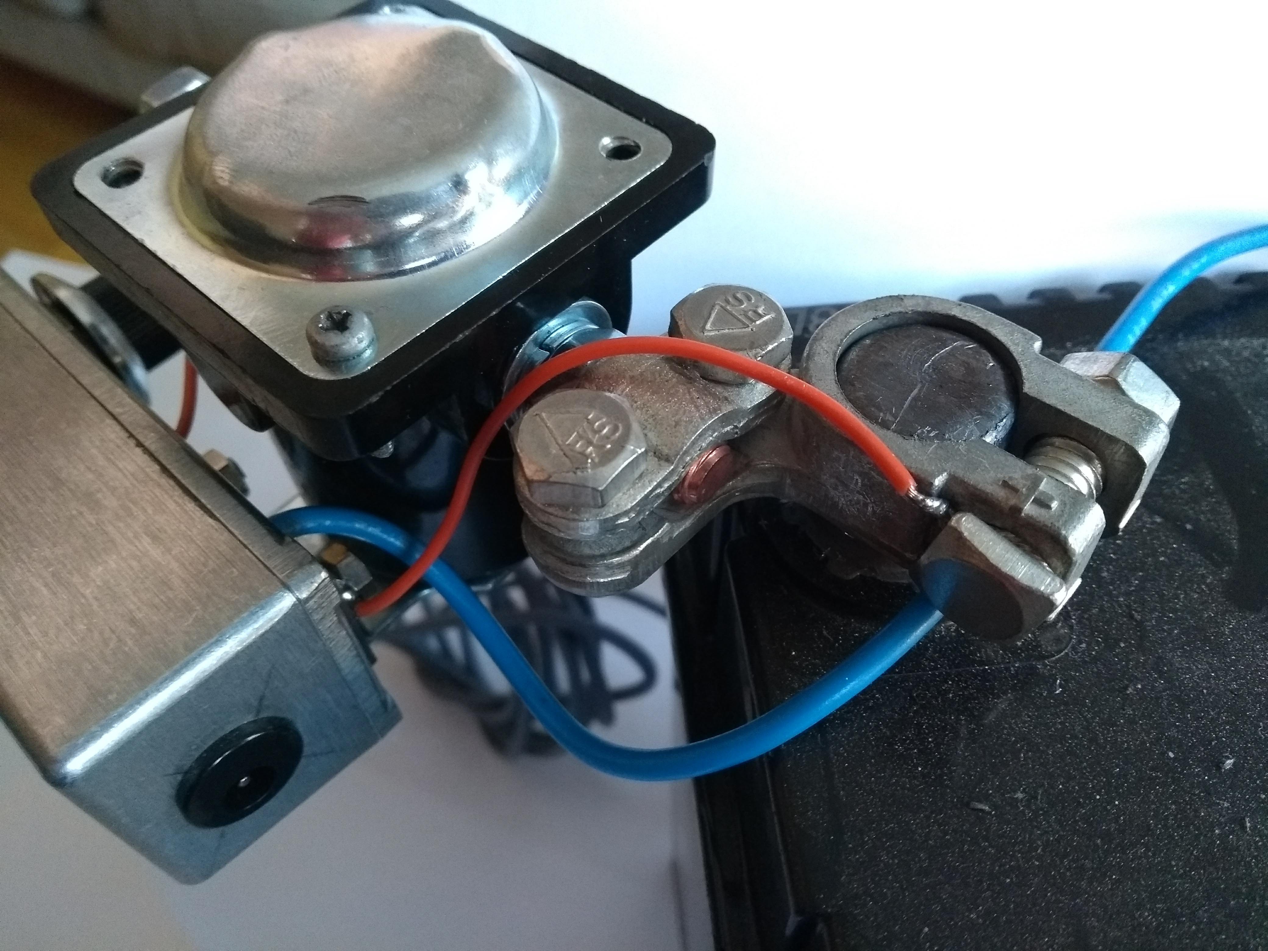 | 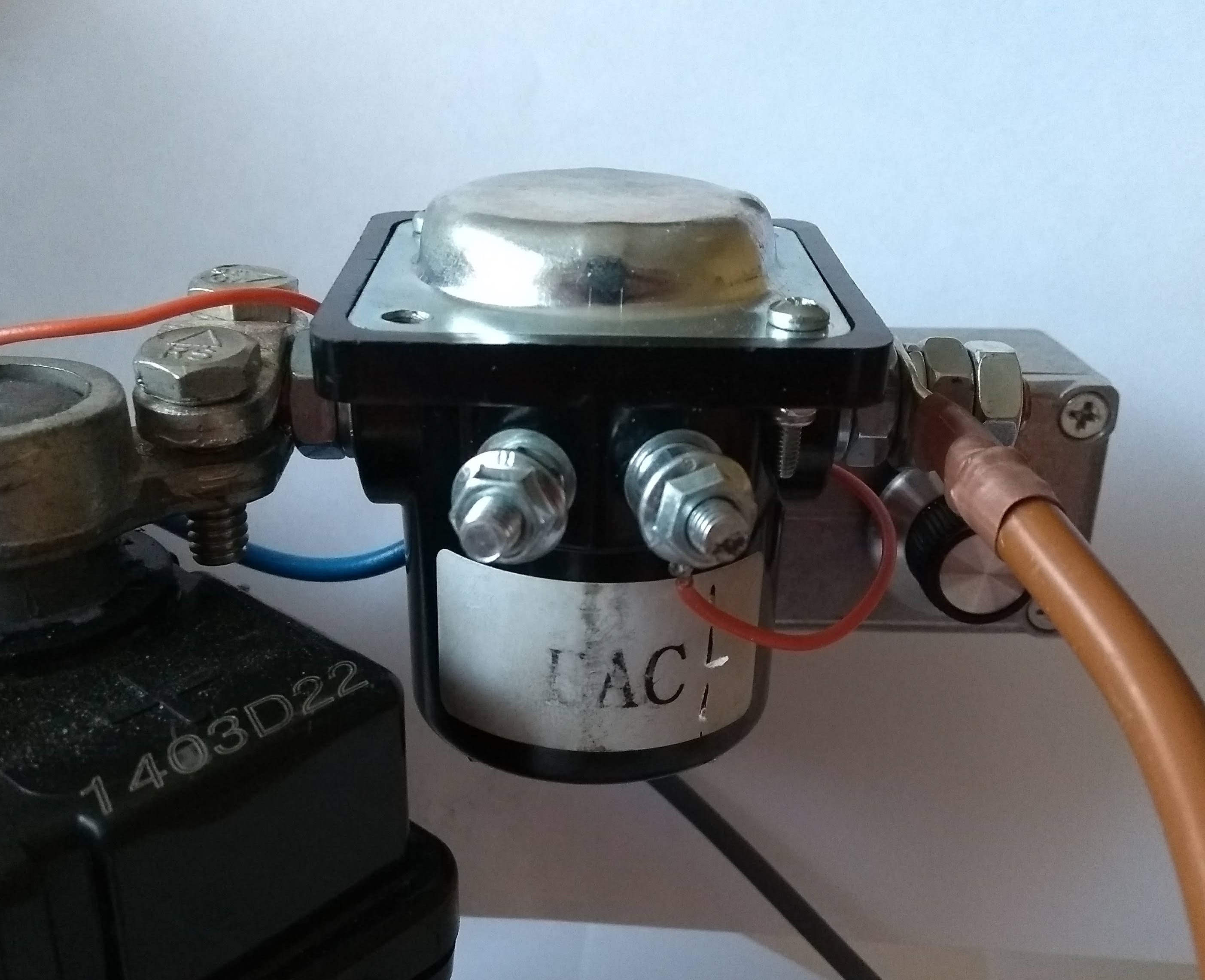 |
| Above: 8mm solenoid terminal studs clamp nicely into battery terminals | Above: Solenoid coil is between small stud on right and mounting bracket |
The solenoid is controlled by a timer circuit built around CD14538BE dual monostable multivibrator operating in non-refrigerable mode. A few passives are used to debounce a basic foot switch as the input. The solenoid coil is driven by a FQP30N06L mosfet. The timer is adjustable between 10 and 110ms via a potentiometer. The circuit Is powered by a separate 9V battery although it could be powered by the car battery with proper decoupling. This is all mounted in a die-cast aluminium enclosure. Note that the solenoid coil is connected between the screw terminal ‘S’ and the mounting bracket. The ‘I’ terminal is the NC contact of the solenoid not a coil connection.
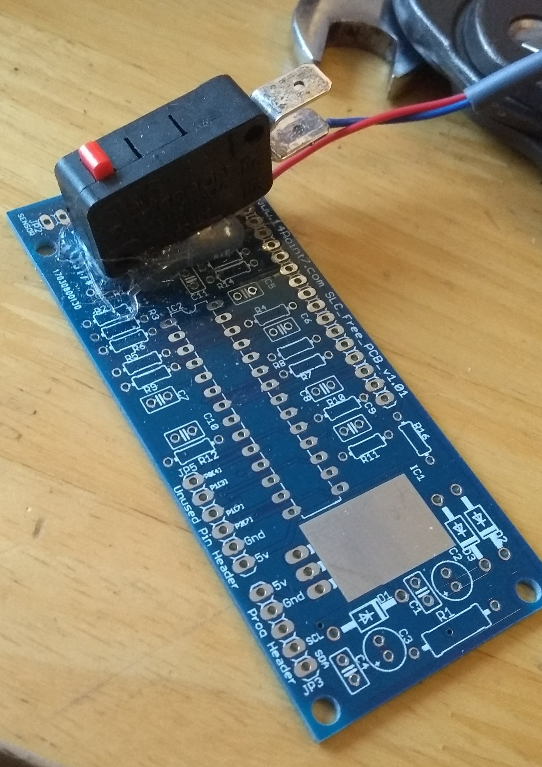 | 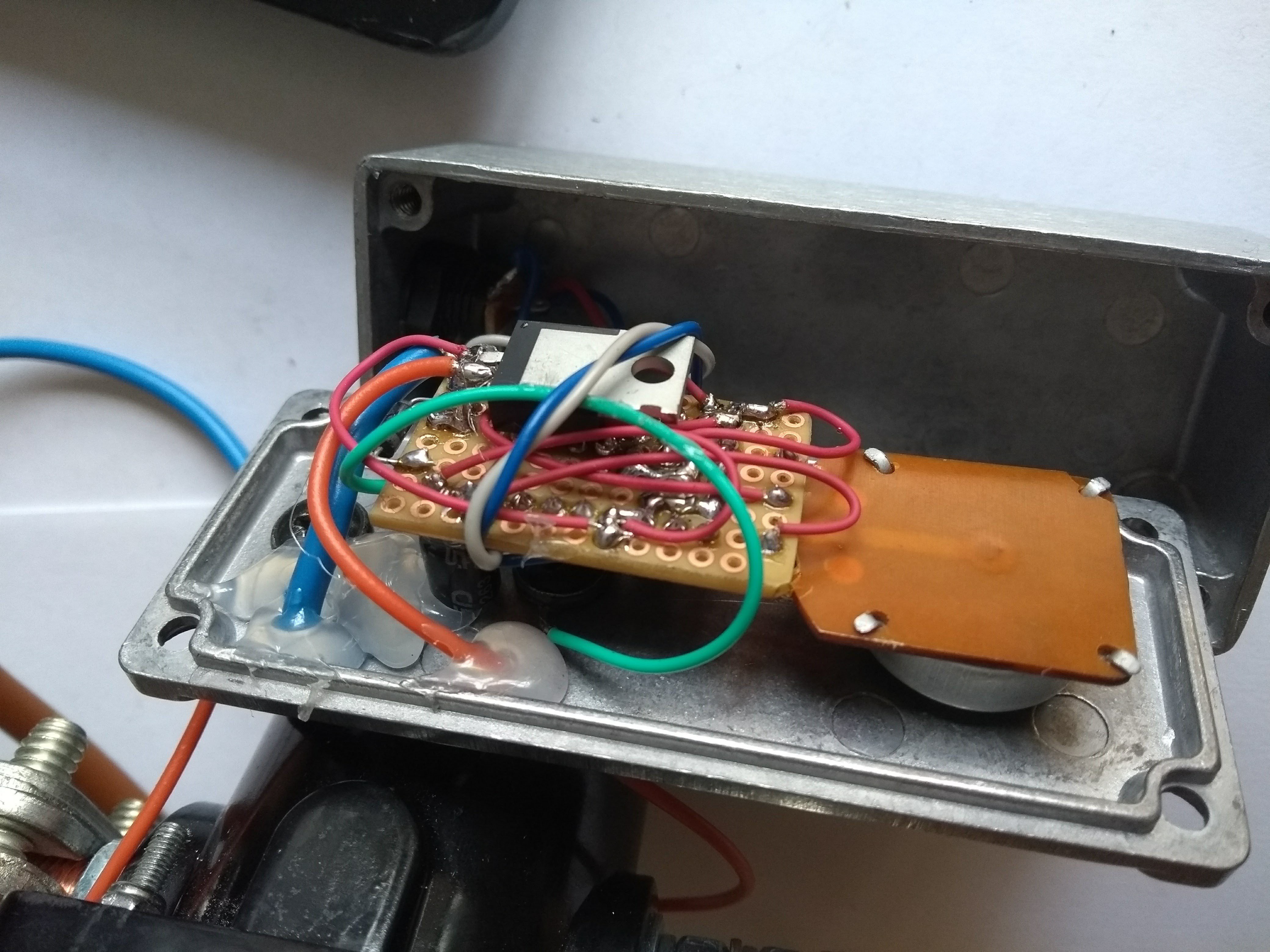 |
| Above: Foot switch. Worked surprisingly well when taped to floor... | Above: Timer circuit |
The electrodes are made using copper nails soldered to short lengths of 8awg stranded cable. The copper nails can be quickly sharpened using a file therefore did not require them to be replaceable. A few layers of heat shrink provide thermal and electrical insulation.
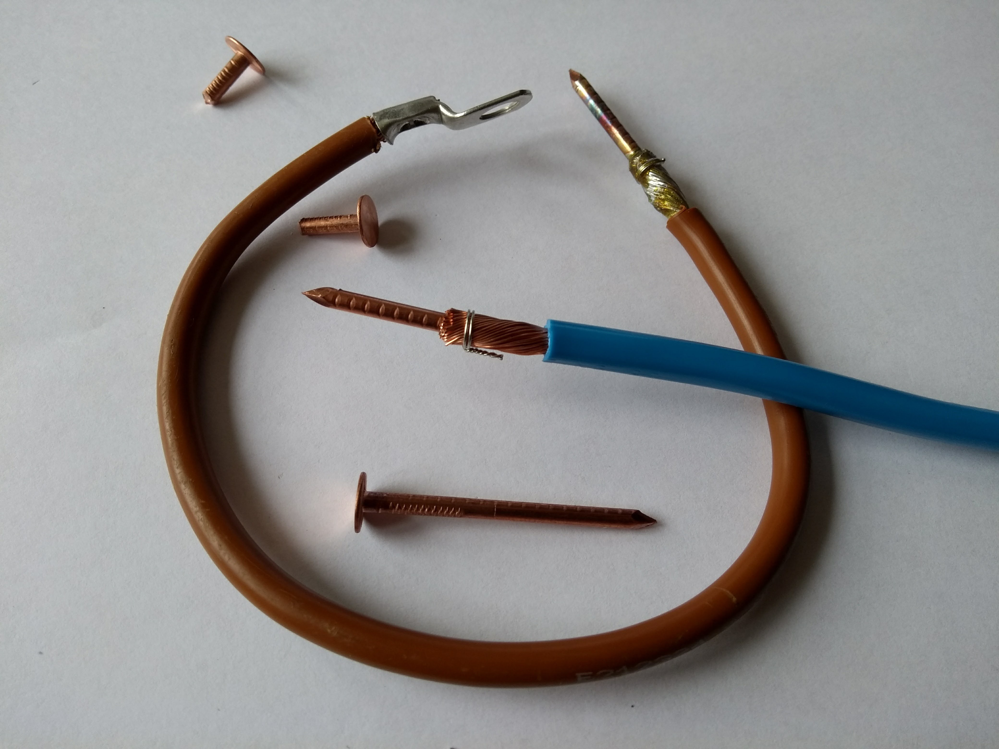 |
| Above: Copper nail electrodes soldered to 8mm stranded cable |
Despite the slow switching of the solenoid, the contacts will stay closed for the same duration as the current that was supplied to the coil. The solenoid takes around 5ms to close but the diode across the coil keeps the magnetic field active, allowing accurate pulses at the 10ms minimum setting of the timer.
Initial Testing
The first tests were rather exciting. The battery is only a few months old and the internal resistance is very low, resulting in very high current pulses which would destroy the nickel strips if the pulse was more than 20ms or so. Lots of flying molten metal…
I experimented with a ‘current limiting resistor’ formed of a length of 1.6mm TIG welding filler wire. This allowed me to run longer lower current welding pulses. I found that the result was a much stronger weld than a shorter higher current pulse. I settled on an approximate length of 50m.
However, after the first pulse the resistor would be very hot, increasing the resistance. This made for unreliable performance.
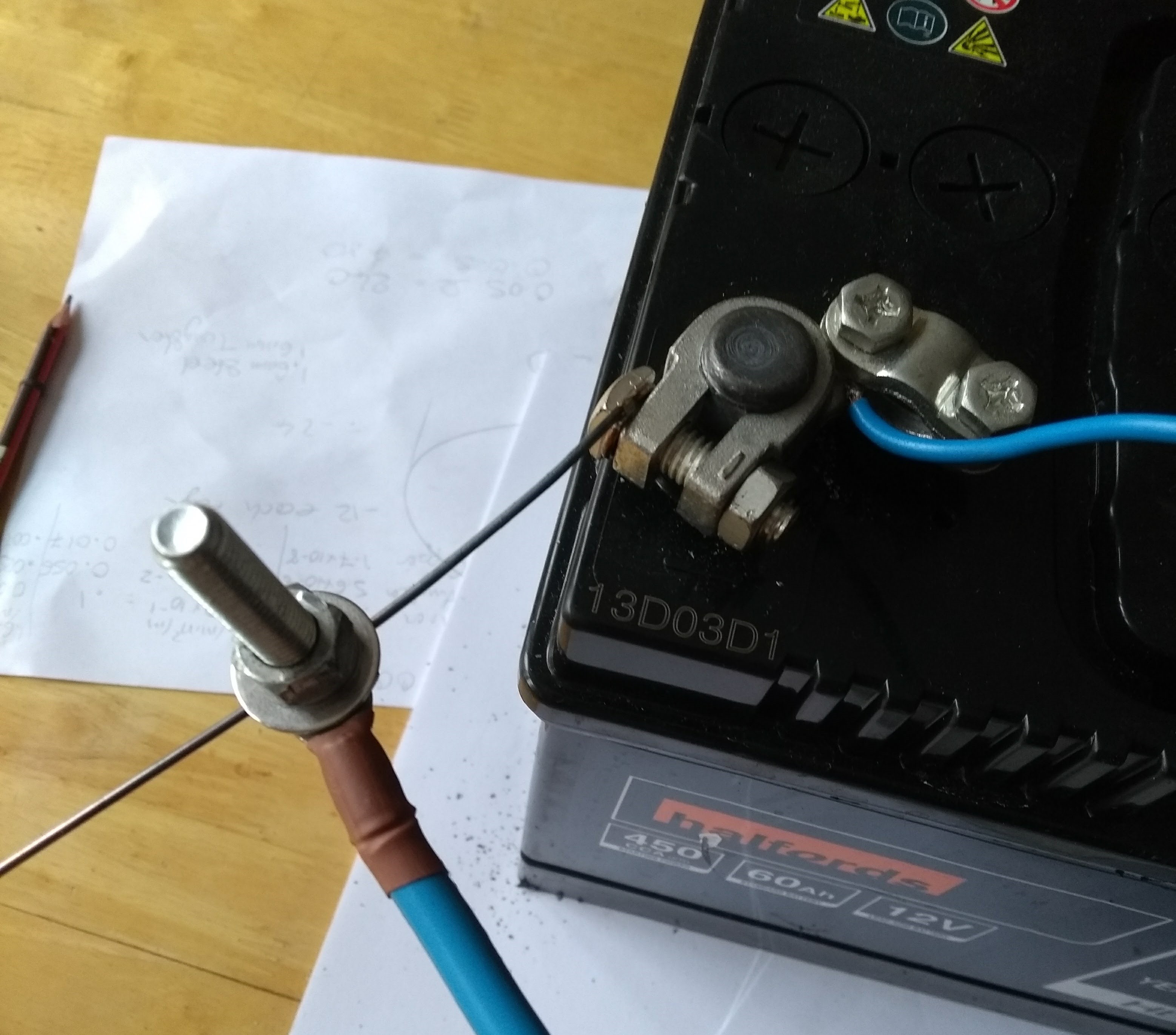 |
| Above: Limiting current with 1.6mm steel wire |
The solution was to immerse the wire in water. I found a nice Ikea plastic beaker which had a very thick base. Some M8 bolts secured everything together and kept the water in.
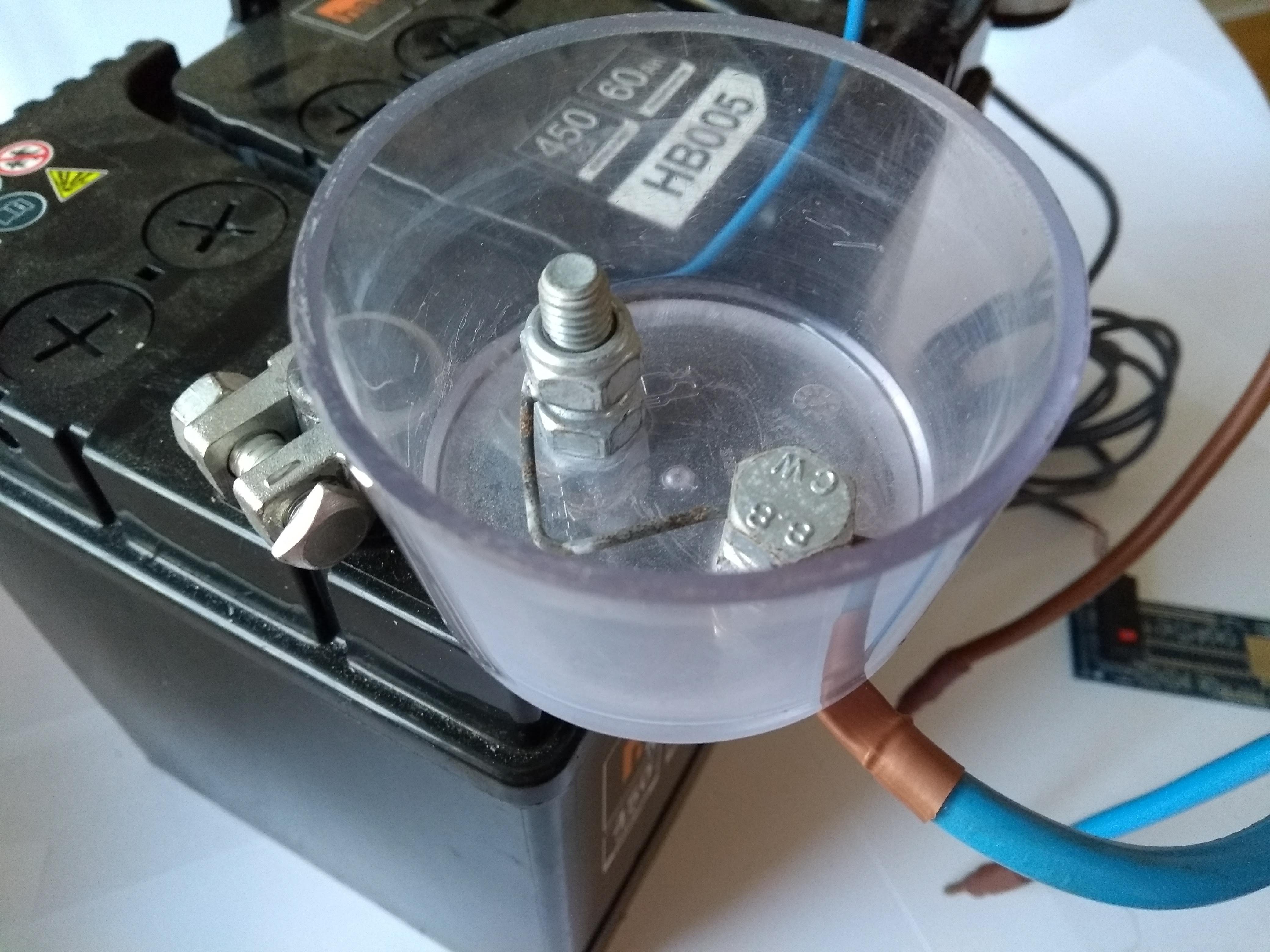 |
| Above: Ikea plastic beaker trimmed and drilled. Filled with water keeps resistor cool |
Conclusion
The welder performed very well in operation when building my battery pack. I made around 600 pairs of spot welds in a period of two hours.
A few points should be noted:
A pulse of around 40ms produced the best welds with my setup. Tearing the nickel strip off the 18650 would leave the welded part still attached to the battery ripping the surrounding nickel.
The car battery should be connected to a charger during use if doing a lot of welds. The voltage will otherwise drop, causing unreliable welding current. I used a 5A constant current charger which can be left connected whilst welding. A charger of 2A or so would probably be fine.
Firm even pressure on each electrode is required to make each spot weld of equal strength.
The welding electrodes get very hot. To stop them buring my fingers I added some more layers of heat shrink. The cables did get warm but not concerningly so.
As the water cooling the resistor heats up towards its boiling point it cannot remove heat as quickly from the resistor due to the Leidenfrost effect (where the bubbles of steam insulate the wire). This allows the resistor to run hotter which lowers the welding current. I raised the pulse timer to 50mS at this point. The water could be replaced, or a larger container used to hold the cooling water.
To review the original design criteria:
- Cheap – As you can see from the parts list, this cost me less than £25. Admittedly I had many of the parts already however most parts could be substituted for something similar.
- Reliable – The device worked flawlessly in use. I will definitely be using this again in future.
- Easy to make – I built this in a few evenings on my dining room table with basic tools. An exception to this was the large crimp lugs for which I borrowed a crimping tool. These could be soldered with a large iron or blow torch if you didn’t have access to a crimper.
- Relatively safe – I would recommend wearing safety goggles due to the occasional flying sparks. Gloves would also be a good idea as well as working outside away from anything flammable. I wouldn’t hesitate to lend this to a friend, something I wouldn’t say of other things I’ve made!