 Lukas Fässler
While the solar charger was originally intended to be used as a standalone device, it can just as well be integrated into other projects. In such applications, the user interface can be left away without sacrificing functionality other than the display and rotary encoder.

One project doing just that is MeshPoint, a rugged wifi hotspot for disaster and outdoor areas. But in most cases, the main application needs to be able to communicate with the solar charger. It wants to know if power is harvested, how full the battery is and so on. It needs to be able to enable and disable the various power outputs and maybe to control the fan. Or maybe it wants to make use of the charger's real time clock and calendar. Or store some configuration data on the charger's EEPROM. Possibilities are endless.

And when it comes to external communication interfaces, all the chargers up to revision D had little to offer other than the USB interface. Depending on your project, adding USB host functionality may be inconvenient or even totally out of the question. There was always the possibility to somehow tap the display's I2C port but there was no extra header on the board for that.

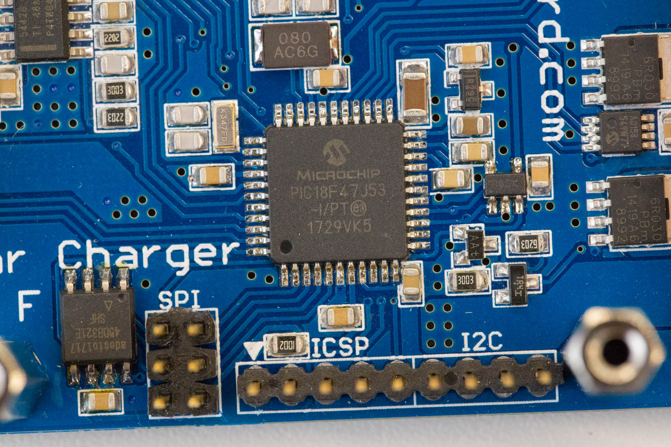
Revision E has finally changed that. The charger now comes with two extra headers, one for I2C and one for SPI. As of now, the PIC acts as a master on both of those buses but slave functionality can be (and is planned to be) added in software. Hardware-wise it is even possible to update the charger's firmware through those interfaces. I must admit that this is not the number one priority to be implemented but its nice to know that the possibility is there.

With the implementation of the USB bootloader next on the agenda I also upgraded the microcontroller to the newly introduced PIC18F47J53. It is extremely similar to the previously used PIC1846J50 and entirely pin compatible so it didn't require any changes to the board. But it has twice as much flash memory (now 128kB) which allows for a feature-rich USB bootloader without runing into any issues memory-wise.

Another nice thing about it is that it has many more PWM modules which means that all four power outputs can now be PWM controlled. Think of LED lighting which is probably one of the main uses of those outputs. As a bonus, it also comes with an 12bit ADC which means four times the resolution on the temperature sensors.
 When modifying the software to fit the new board and microcontroller, I noticed that my pin choice for the external SPI slave select signal was somewhat unlucky. I happend to pick one of the few pins without PPS (peripheral pin select) functionality which can be a problem if you try to use that interface with the charger configured as slave. The fix was easy, just swapped two pins but required a slightly modified board. That's why the current version is now revision F.
Discussions
Become a Hackaday.io Member
Create an account to leave a comment. Already have an account? Log In.