 W5FCX
W5FCXYou can find the schematic ready to edit and go on EasyEDA here.
Source code for the Arduino sketch is attached and below. Note that it uses the TimerOne library to provide higher-resolution Timer1 frequency control for the Pulse Width Modulation to control the fan speed.
THEORY OF OPERATION
The controller uses a 10K thermistor to sense remote temperature from the target device.... in my case, a large heat sink on a 160 watt linear amplifier. I used Kapton tape to insulate the themistor from direct contact with the heat sink. My goal was to keep the temperature below 150 degrees F, as the amplifier has a shutdown temp of 170 degrees and was becoming too hot for my liking during extended usage periods.
The thermistor is part of a voltage divider circuit, which is fed into A0, an analog input port whereby the voltage reading is taken. That reading is then scaled based upon the known 5 VDC reference voltage provided as part of the Arduino nano. This reference voltage is particularly accurate, but for this application close is good enough. In practice, I found the temperature readings to be within a degree or so.
The temperature is scaled and converted into degrees C, then degrees F, then used to make control decisions. I wanted the fan to switch on anytime the temperature rises above 90 degrees F and to start out at a medium speed. I found that lower speeds weren't especially useful and caused the PC fan to make unseemly sounds that didn't seem healthy, so I opted for a moderate low temperature fan speed.
As the temperature rises, the PWM duty cycle is modified in a linear fashion to speed the fan up and increase its cooling capacity. Once the temperature exceeds the maximum target, the fan is switched to full-speed mode.
Since the Nano has a built-in LED, I decided to blink that LED whenever the relay is closed to indicate the fan should be running.
The relay chosen is a 1-coil latching relay - a Panasonic ADW1105HLW capable of switching 16 amps - totally overkill for this application, but I also had this component from another project, so I grabbed it and used it. Latching relays switch between states (open / close) by providing a 30 millisecond or longer pulse to the single coil. In this case, the 5 VDC relay requires up to 40 ma. for 50 milliseconds to switch the relay, after which there's no need to continue providing any current as the relay latches into the desired state and stays there.
I used a couple of digital output pins and a simple timer to provide the latching relay polarity reversal logic and switching pulse. While the maximum per pin current of 40 ma. of the Arduino is being used, I didn't feel like adding another external component like a transistor was warranted as it's within the Arduino's maximum current rating and only flows for 50 ms.
This project works perfectly and keeps my amplifier cool and purring like a kitten! And it was fun learning some new things about Arduino, PC fans, PWM and thermistors in the process.
SKETCH
//
// TempFanController - Temperature-based Fan Controller
//
// 6-2-2018 W5FCX (R. Braddy)
//
// This Arduino Nano sketch manages variable speed fan for cooling a ham radio linear amplifier. It switches the fan on above the low temperature cutoff then ramps the
// fan speed up to full speed using timer1 for high-res pulse width modulation. For this application, a Panasonic ADW1105HLW 1-coil latching relay left over from
// another project was used to switch the 12 VDC to an inexpensive Nidec BETA V TA450DC variable speed fan. This fan has a built-in MOSFET and 4-wire fan control
// designed for PC cooling and draws about 0.8 amps. The thermister is a common 10K NDC device coupled with a 10K voltage divider resistor.
//
// TimerOne library provides the 22.5 KHz output frequency for PWM use on pin 9 using Timer1.
//
// This sketch derived from various articles and experimentation. The Thermister temperature...


 Storken
 Coders' Cafe
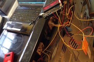
 Andreas Mergner
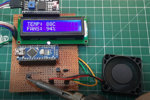
 Sagar 001
Nice project! I'm wondering if it's a PTC or an NTC thermistor, and how did you find the formula to calculate the temp?
I'm also wondering why this needs a relay. Couldn't you just set the PWM to 0 when you don't need the fan running?