 Ryan Logsdon
Topics to be expanded upon over the course of our project:
* herd immunity
* basic physics of an earthquake
* millisecond timing in IOT devices on different networks
* how to build our own shake table
Earthquake detection & early warning systems
Already have an account? Log in.
To make the experience fit your profile, pick a username and tell us what interests you.
Topics to be expanded upon over the course of our project:
* herd immunity
* basic physics of an earthquake
* millisecond timing in IOT devices on different networks
* how to build our own shake table
Chip Container F3D.zipFusion 360 master files for a small 4-drawer containerZip Archive - 874.32 kB - 07/16/2018 at 20:15 |
|
|
MicroSD Card Holder.zipFusion 360 master file and print file for a 10-card MicroSD card holderZip Archive - 335.85 kB - 07/16/2018 at 20:15 |
|
|
Chip Container STL.zipFusion 360 print files for a small 4-drawer containerZip Archive - 84.54 kB - 07/16/2018 at 20:15 |
|
We've got lots and lots of data, and we need to do more than just save a copy locally.
In this log / tutorial, we're going to detail how we set up our own Google Cloud virtual machine with a simple database. You'll be able to use this to store all of your sensors' data. Now, on to the software part of our hardware project...!
Why Google Cloud Platform instead of Amazon AWS?
(Google hasn't sponsored us; we just really like their services)
In all, it seems that Google looked at everything Amazon was doing with cloud computing, and Google met Amazon head-to-head where AWS does things well, and Google innovated where AWS is lacking.
Creating the VM
Logging Into the VM and Setting up the Database
The 1st step here isn't necessary, but it'll speed up your log in times...
sudo apt-get update
sudo apt-get upgrade
mysql -u root -p
CREATE DATABASE myHardwareProject;
USE myHardwareProject;
CREATE TABLE test (
    ID int NOT NULL AUTO_INCREMENT,
    sensorName varchar(20) NOT NULL,
    sensorValueA FLOAT(10,9),
    sensorValueB INT,
    PRIMARY KEY (ID)
);
Have fun!
We're making progress towards reading our 7 different accelerometers / IMU chips.
At the moment, we've wired up & are reading the I2C data from the following three chips:
The ones we're still working on are:
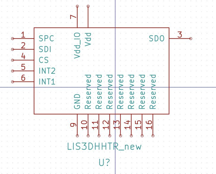
And the 7th chip, an STMicroelectronics LIS3DHHTR, is out of stock with a 14 week lead time, so we're ruling that chip out before spending any more time on it.
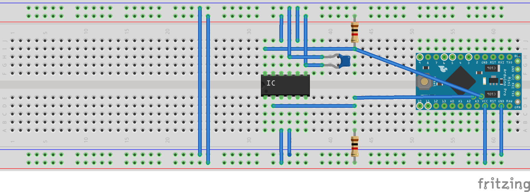
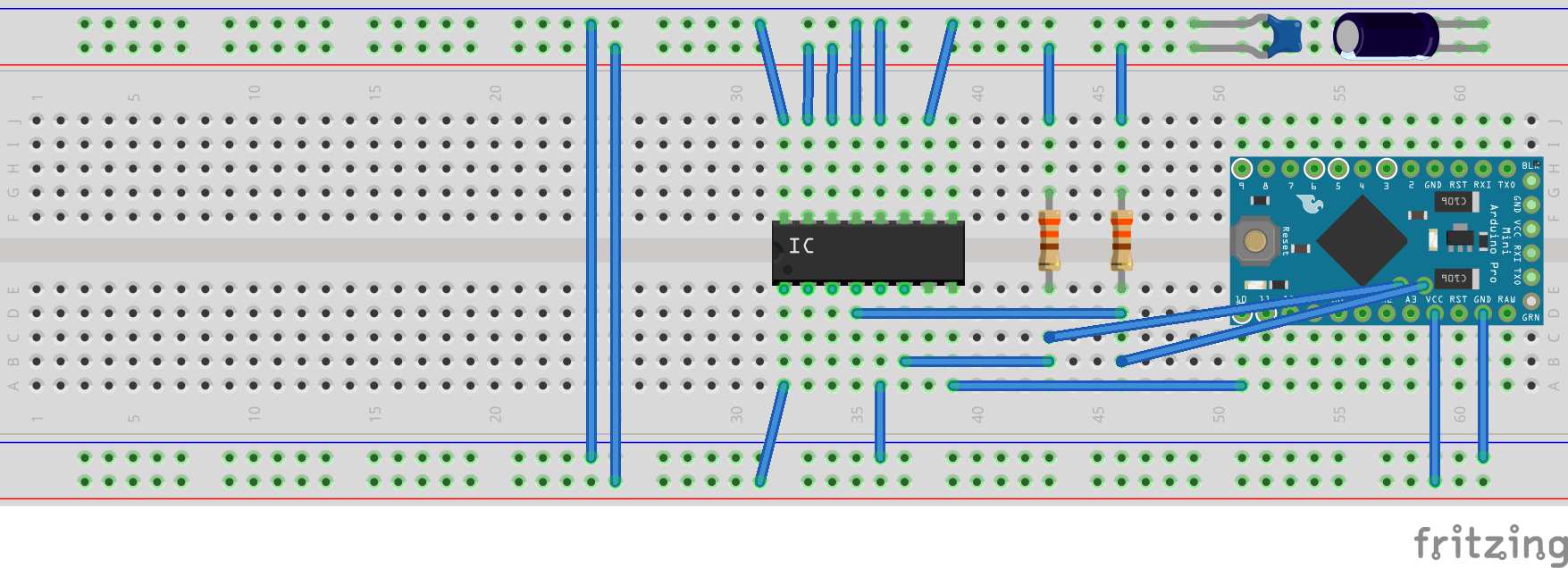
Now for a walk-through of the pin layouts. The controllers are all Arduino Pro Mini boards, and the "IC"s are the respective Kionix and ST chips.
KX022
resistors are 1k Ohm
capacitor is 0.1 uF
KX112
resistors are 4.7k Ohm (1k is fine as well)
capacitor is 0.1 uF
LIS3DSHTR
resistors are 330 Ohm
capacitors are 0.1 uF and 10uF
We're currently writing the code to test data sampling from 7 different inertial measurement unit (IMU) chips, and we'll have a write-up on that progress soon.
For now, there's a fun, little trick in Fusion 360 to show.
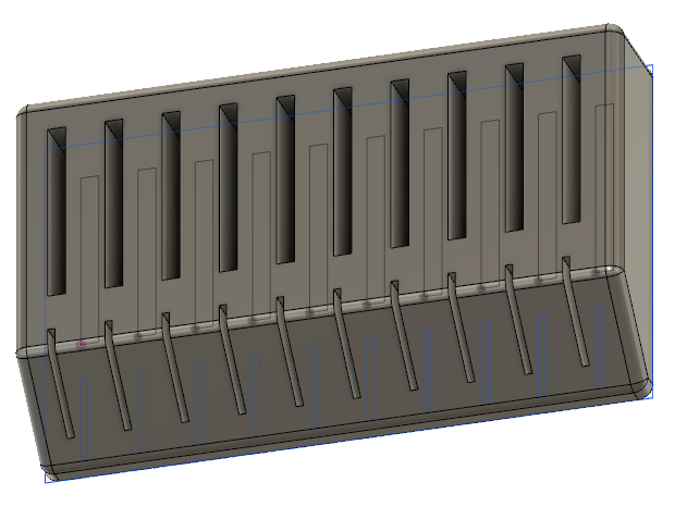
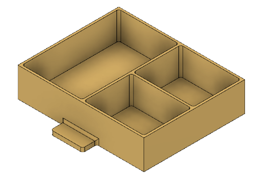
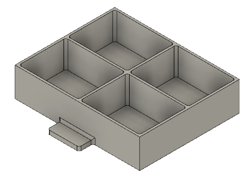
We need a much better way to organize our MicroSD cards and our custom boards with the IMU's. Enter Fusion 360.
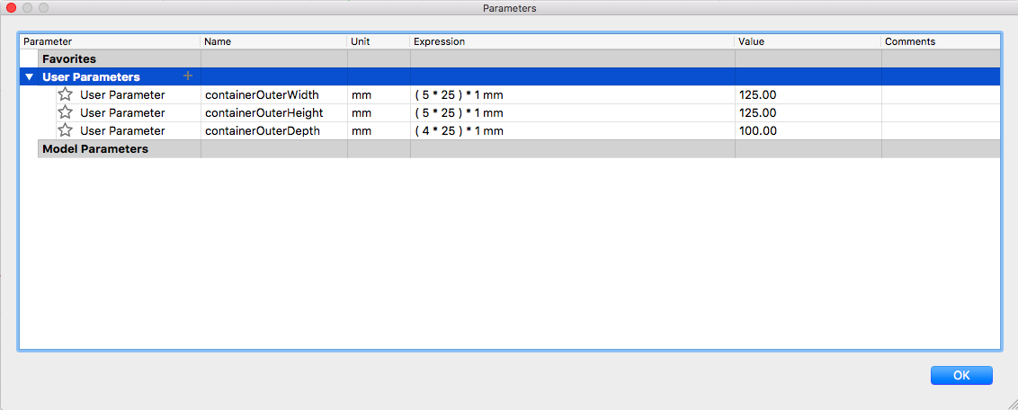
First, we need to store the Raspberry Pi hard drives (ie: the MicroSD cards and their larger card holders). And with rapid prototyping comes rapid mistakes in sizing. Did we give enough wiggle room? Too much? In order to combat this issue, we're going to work with variables in Fusion 360 --- and only variables, no absolute dimensions.
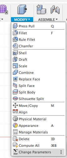
To build our MicroSD card holder, here...
... we're going to input some custom dimensions by going to Modify > Change Parameters > User Parameters.
Now we can print our design, see if we like it physically, and make small tweaks without having to redesign it. All we need to do when drawing is type our User Parameters instead of physical lengths. We can also use equations such as "containerOuterWidth - 2 mm" or "shell/2 mm".
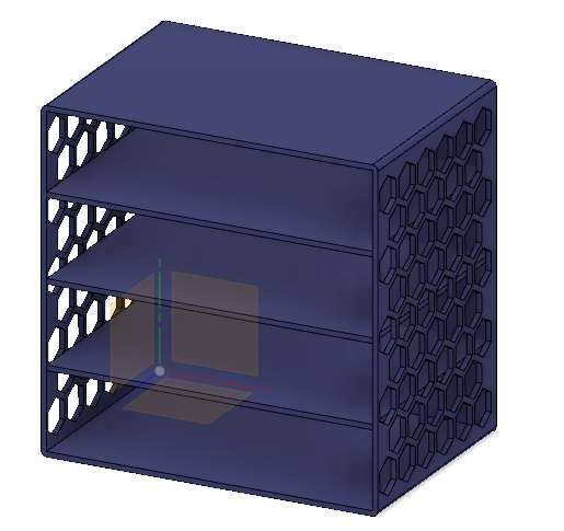
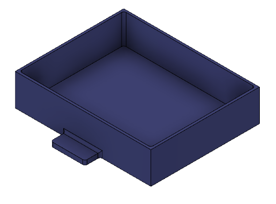
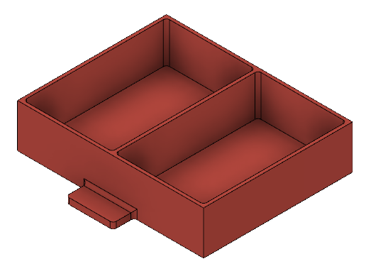
This becomes especially useful when working with multiple parts, as we did when building a little enclosure for our more-than-one-dozen custom boards.
If there's an interest in the original files, let us know, and we'll post them with a how-to guide for building them from scratch!
Thanks,
Ryan
links to the files:
4-drawer Container, Fusion 360 files
We've run into a hardware issue, needing an FTDI board to connect our 3.3 volt Arduino Pro Mini boards' row of programming headers to our laptops. Those boards are on their way now, and with them in place, we'll be able to directly interface with our custom hardware. In the meantime, we've switched gears to get the software ready.
In order to evaluate our 7 different MEMS accelerometers, we're going to need to test a few things:
* signal drift
* delay between physical inputs (motion) and signal outputs
* ease of programming (we've already settled on I2C communication instead of SPI communication because of the libraries that are at the ready for I2C on the Arduino; plus the Arduino Pro Mini boards have nicely labeled
And in order to do this, we need 3 plots to stream out from our Arduinos.
To access the serial plotter, we simply setup the sketch with:
void setup() {
  Serial.begin(9600);
}
Next, we want to keep the graph from jumping erratically when there are very high or low values read from the chips, so we plot a constant upper bound and lower bound in the loop:
void loop() {
  Serial.print(1.0);        // upper bound of expected data
  Serial.print(-1.0);       // lower bound of expected data

  // ...

}
And all that's left is to plot the input data from the I2C comm:
I2c.read(EVAL_CHIP_1, 0x03, 6);
  x = I2c.receive() << 8;
  x |= I2c.receive();
  y = I2c.receive() << 8;
  y |= I2c.receive();
  z = I2c.receive() << 8;
  z |= I2c.receive();

  Serial.println(x + ', ' + y + ', ' + z);
Notice that the final "Serial.println(...)" is a full printLINE and not just a print.
With this code, we should be able to plug-and-play with our custom boards next week! Let the accelerometer evaluations begin!
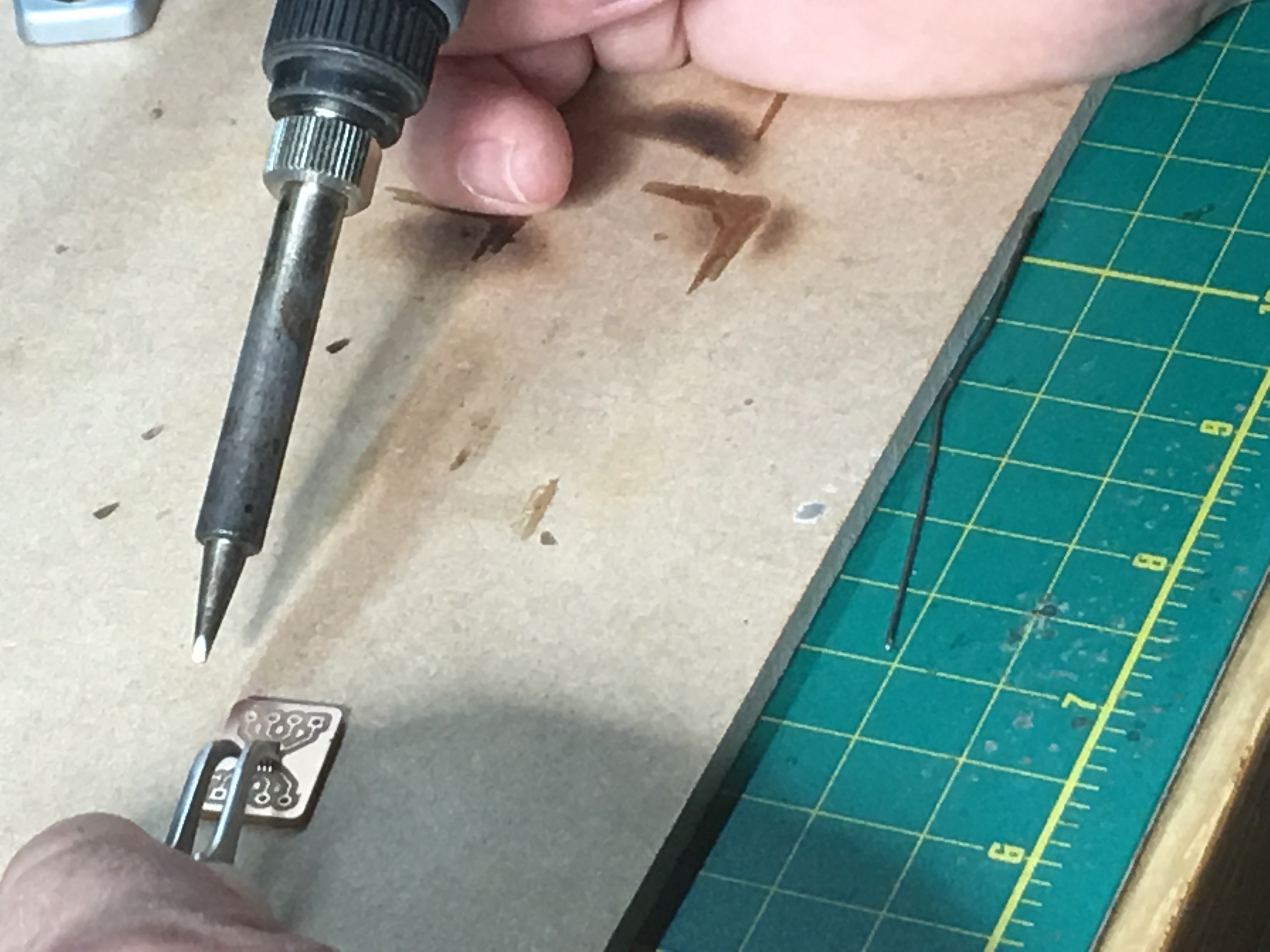
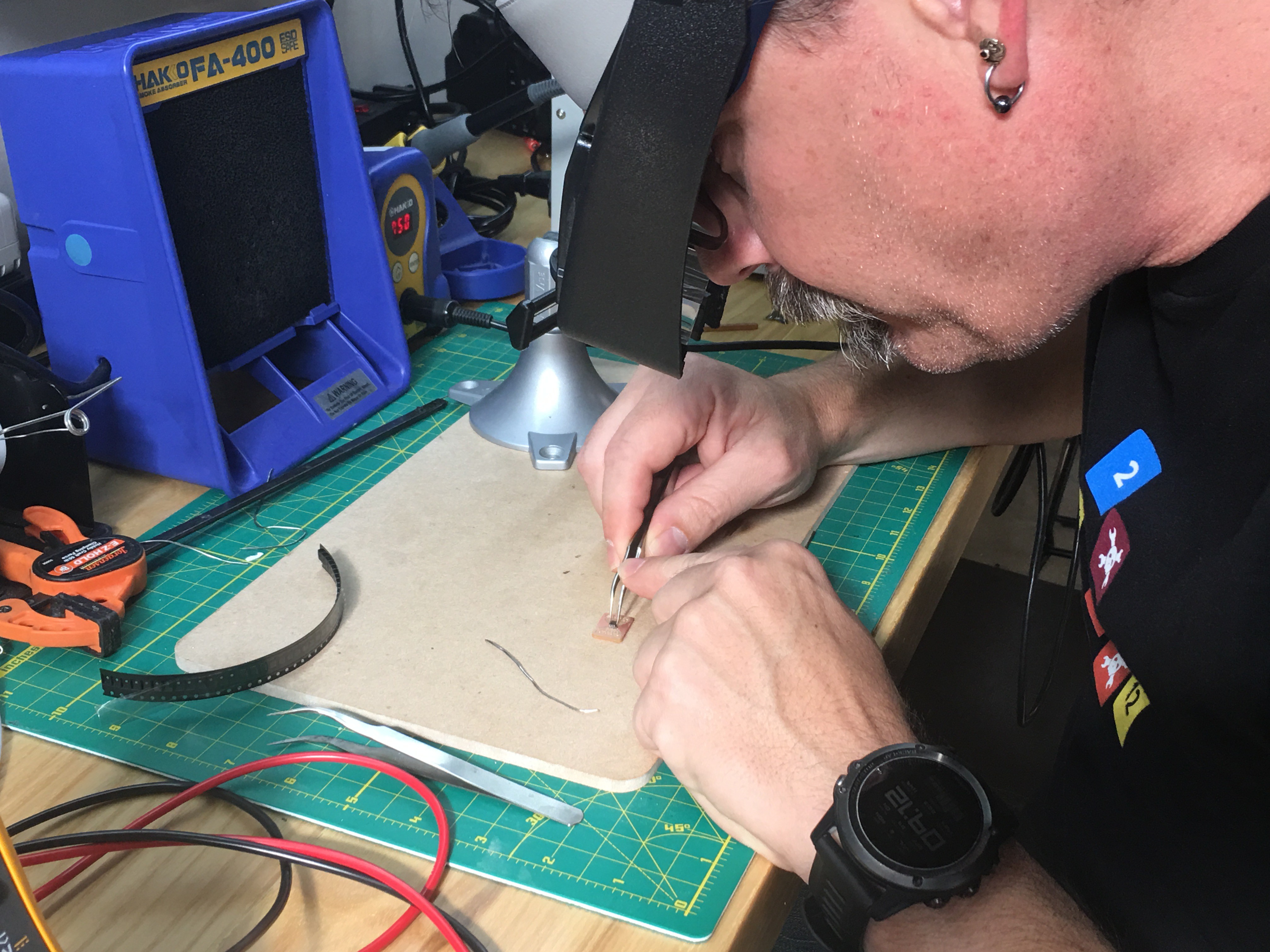
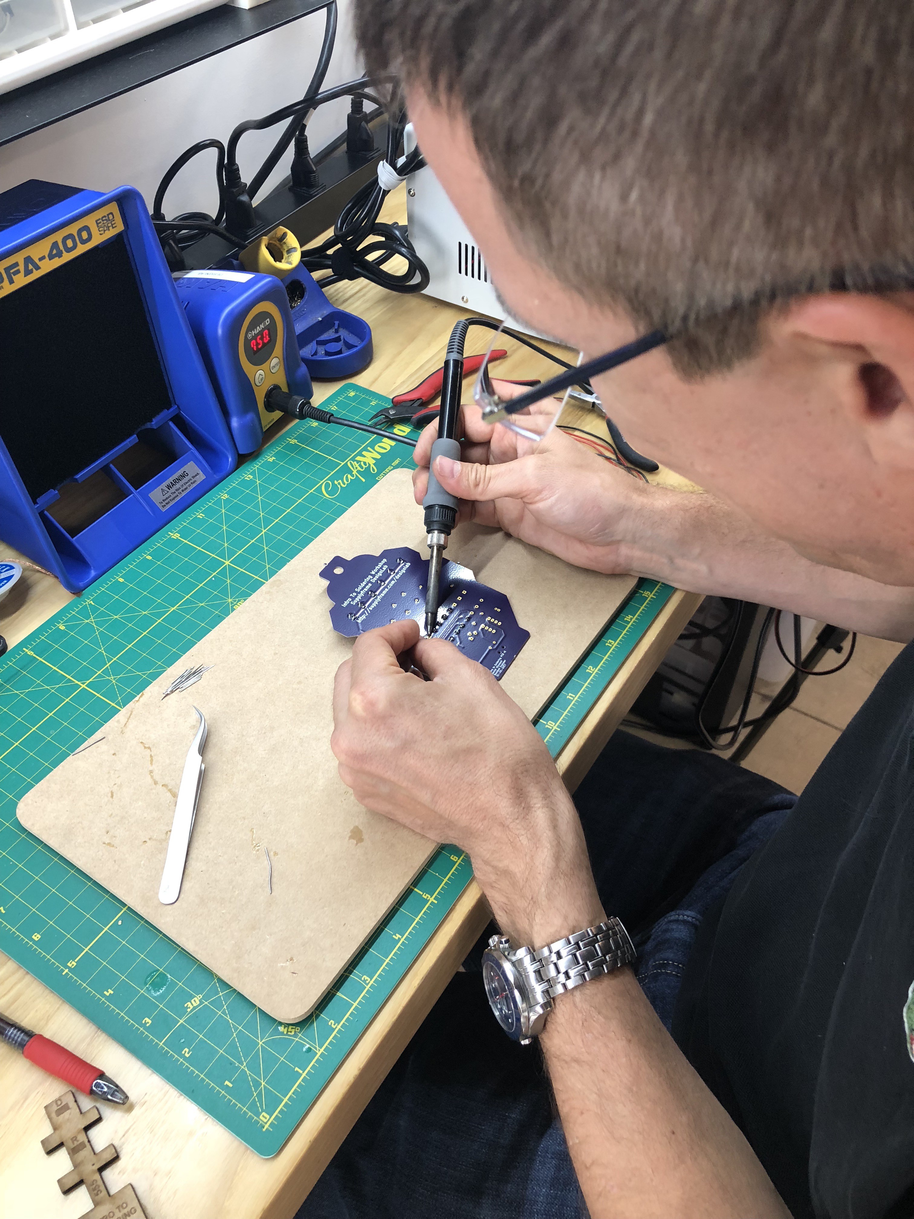
This week, we continued the board assembly process by soldering pins on all of our test boards. Unfortunately, we had a slight setback when a few of the boards had the pins soldered before the chips were soldered in place, resulting in quite a bit more work than anticipated.
Backtracking required use of the hot air gun to re-heat the solder around the pins, being careful not to melt the incorporated plastic, yet burn our fingers as much as possible. Then, we used copper wick to remove any remaining solder until the board was once again flush, and we were ready to incorporate the chip.
In total, we will be testing seven different chips across three models. This will allow us to choose the most accurate, reliable and easy-to-use chip for our needs, given that different accelerometers could have different levels of drift, have different levels of calibration difficulty, and many other factors.
Some pics of the chip soldering:
-Sean
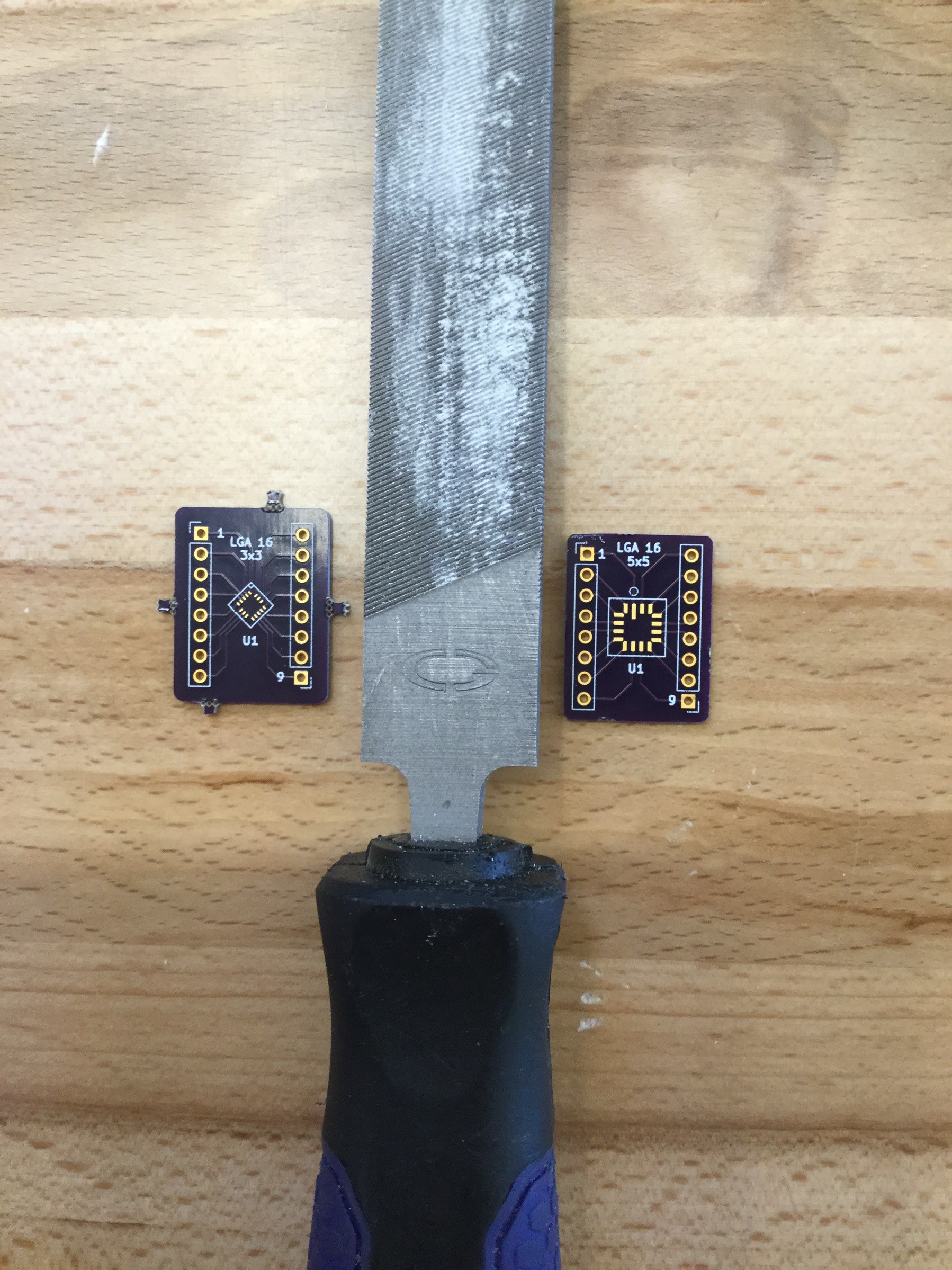
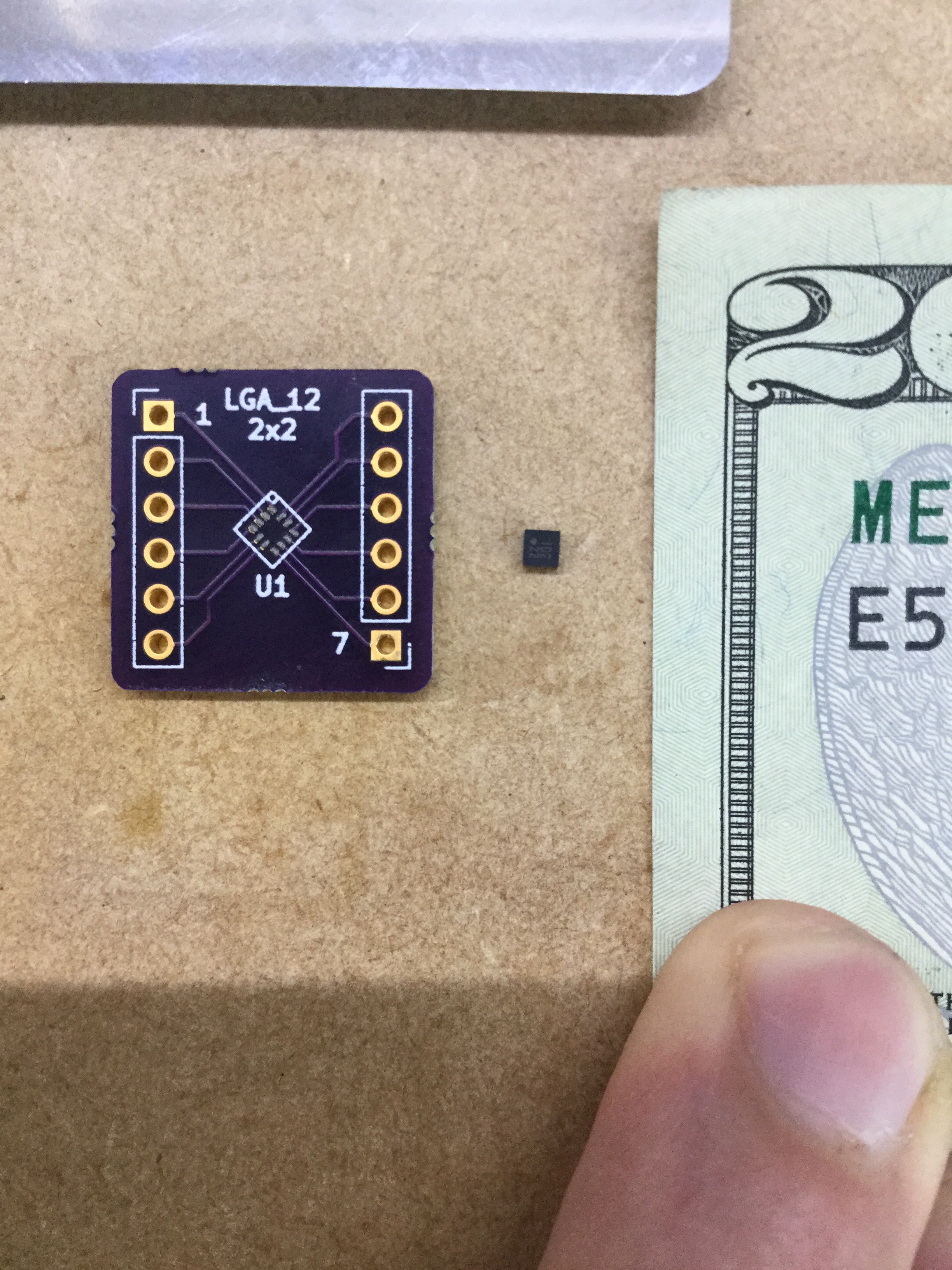
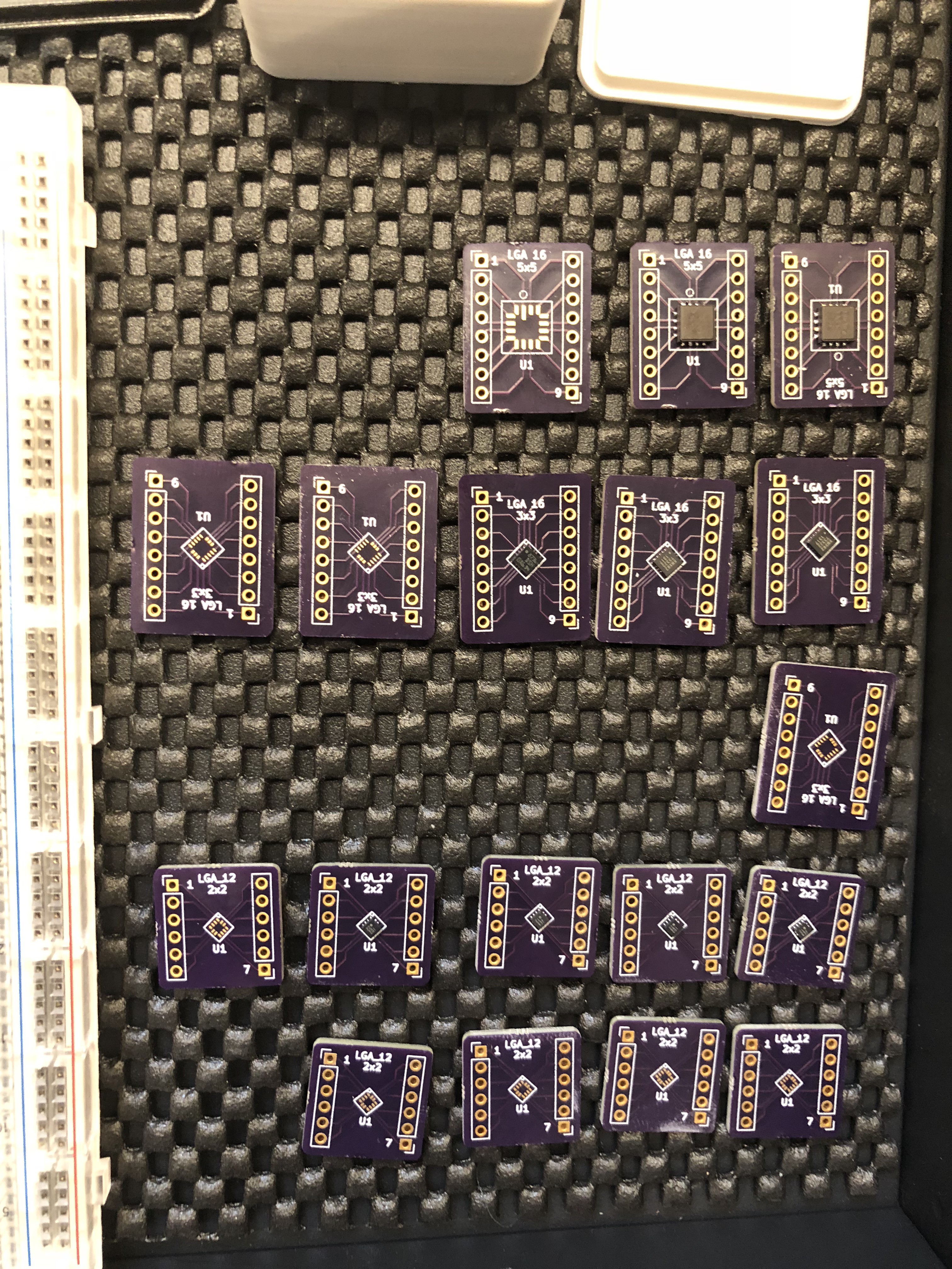
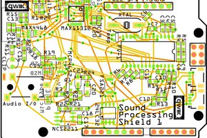
This week we had our circuit boards delivered, and began pasting accelerometer chips to them so we can start testing and refining the prototype. To do so, we had to learn a few new tricks, including the proper use of solder paste, stencils, and hot air guns. When we're done, we'll have 1`4 boards with three different types of accelerometer chip, from which we will choose an accelerometer for the final product.
Here's a brief overview of the process:
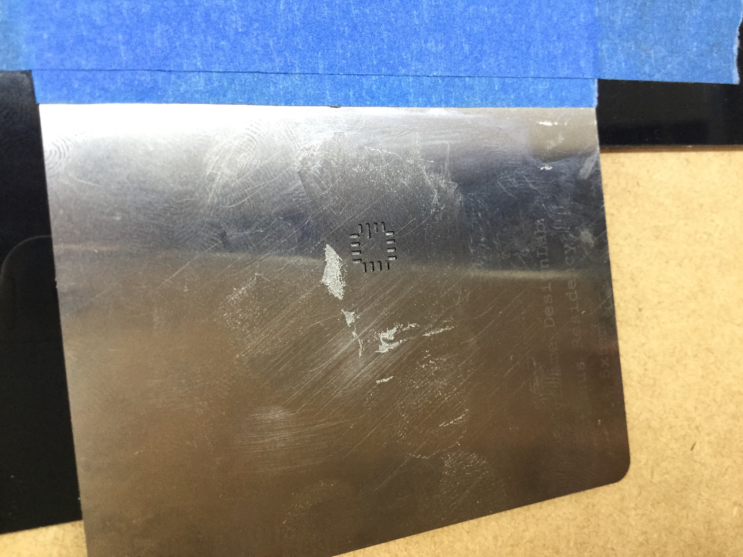
1. File down any projections on the sides of the boards.
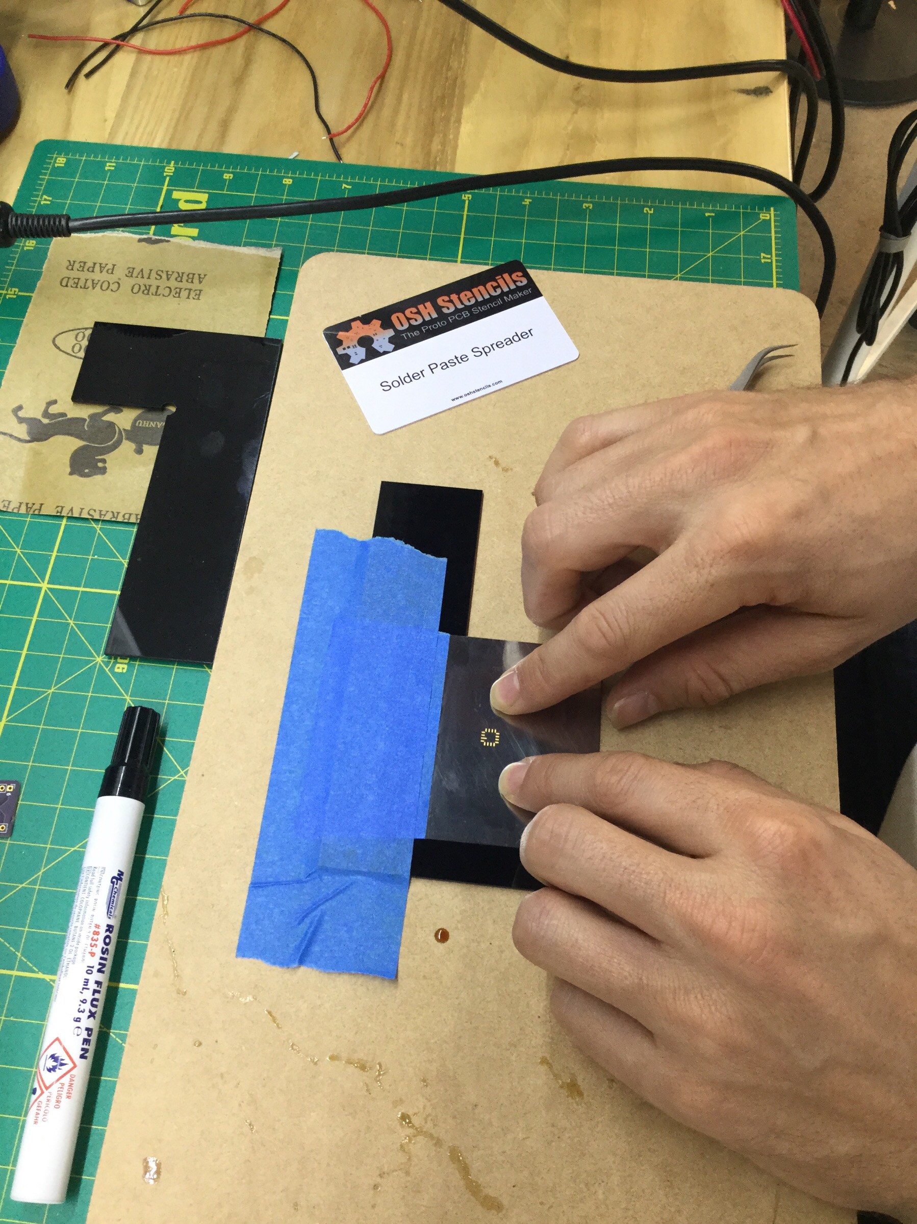
2. Align the stencil sheet to the circuit board, and tape the sheet in place.
3. Turn on the hot air gun and set the temperature to the melting point of the solder paste, as indicated on its data sheet.
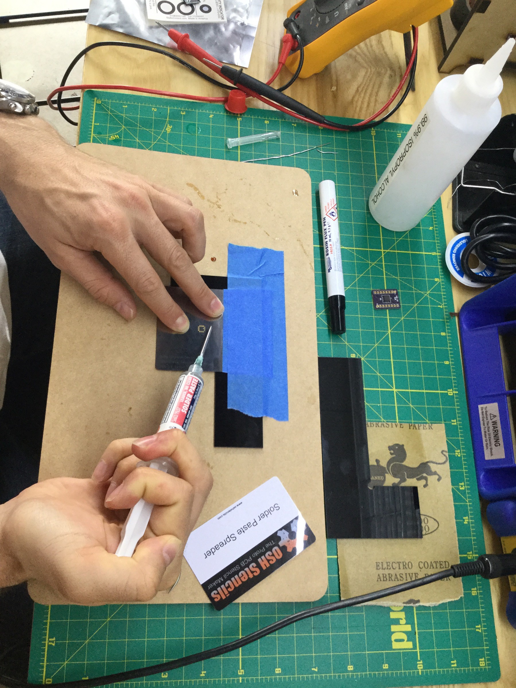
4. Place a small dab of solder paste just above the stencil on the sheet.
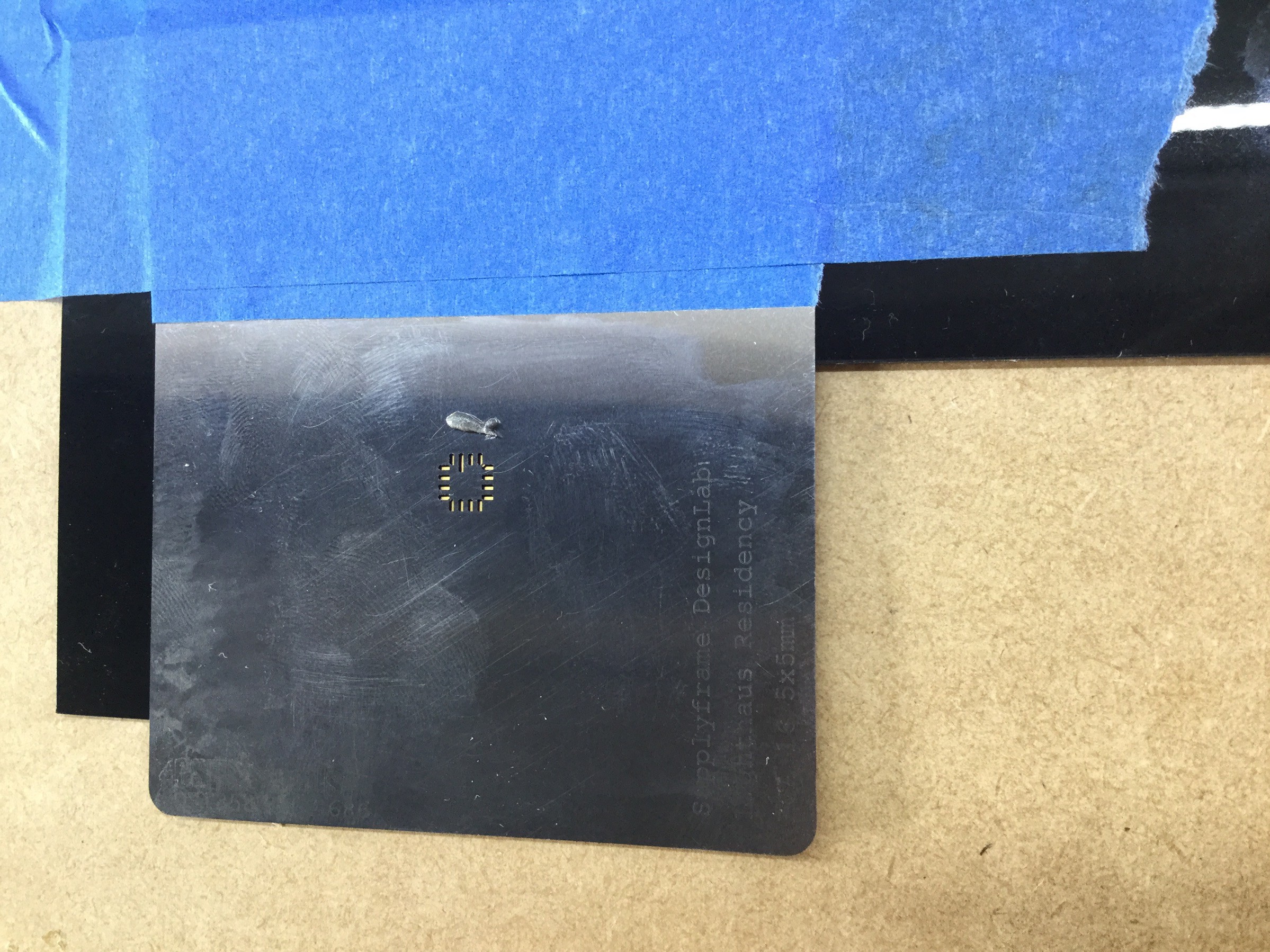
5. Use the solder paste spreader (any card works just as well) to scrape the solder paste across the stencil. Keep pressure applied to the stencil to ensure no paste is pushed anywhere except the stencil area. Spread the paste until the stencil is completely filled in, and you can no longer see the gold of the circuit board.
6. Gently remove the board so as not to disturb the solder paste. It should not look like this:
7. Use tweezers to delicately place the chip in the correct orientation on solder paste on the board.
8. Using the hot air gun, heat the board using circular motions until the solder paste turns matte gray.
9. Then, aim the gun directly at the chip until the solder paste melts and becomes silver, about 30 seconds.
10. Remove the hot air gun, and use the tweezers (board will be very hot!) to inspect the board for bridging.
11. Use a multimeter to test each pin against the rest, looking for bridging. Often chips will have two or more pins acting as a common ground, these will show a connection. Read the chip's data sheet to confirm that these pins are indeed common grounds, and not just bridged.
12. Bask in the satisfaction of pasting your own circuit boards!
-Sean
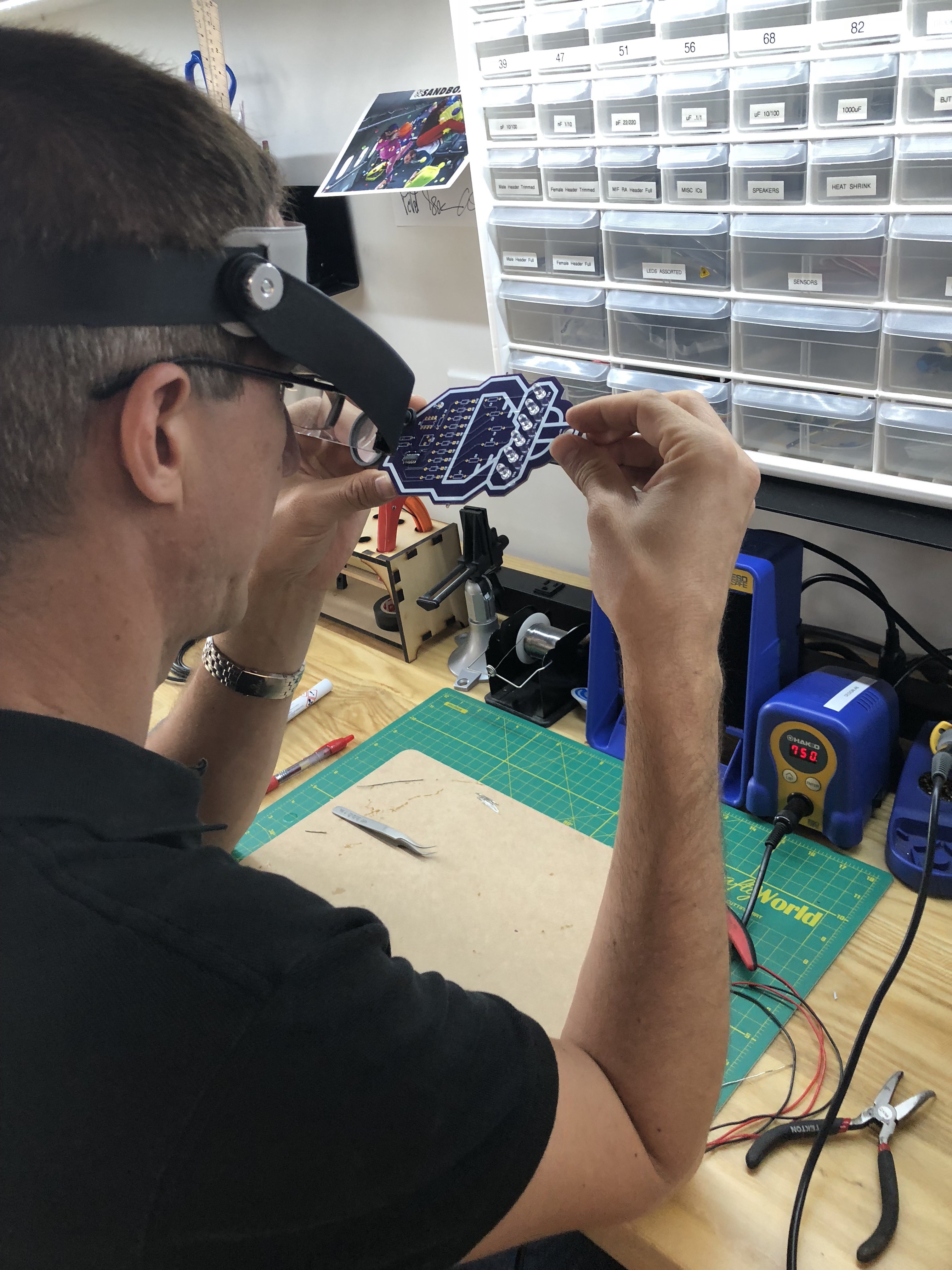
In preparation for next week when we'll be working with custom boards, Sean and I improved our soldering skills. Who says a programmer and an MBA student can't solder like champs?
As it turns out, my issues in the past have been twofold:
1. an assumption that the electronics parts can't take sustained heat has led me to solder FAST and at low heat. This week, we've cranked the dial up to 750 F, and taken our time to pre-heat the pads as well as the electronic components,
and
2. using rosin-core solder incorrectly. How? By not clipping it off a few inches at a time. I've always unraveled the solder wire right from the spool, and after a few connections, it seemed to get harder and harder. As I've learned this week, it gets more difficult because the rosin is melting well into the spooled wire. Solution: clip a few inches off at a time.
A step-by-step guide, using KiCad to make a simple breakout board for tiny, tiny chips!
This is part 2: creating the physical component layout.
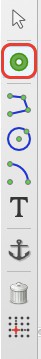
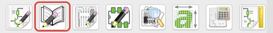
Open the EESchematic ("Electronic Schematic Editor")
Import Our "Part 1" Tutorial Work
Now that we've created a logical chip, we can import it into KiCad.
Preferences > component libraries > add > (find your newly saved file) > ok
Place the Component on the Board
Place (as in File/Edit/View/.../Place) > Component > (type your component's name in the filter) > select the component > ok
Working with the Footprint
Select the Footprint Editor icon
File > New Footprint > (add a name) > ok
Change the Default Text
Change "REF**" to "U**"
Add a Pad
Add a pad to your footprint. Drop it in place anywhere.
Right-click > Edit Pad > (change "Pad type" to "SMD" & change "Shape" to Rectangular").
Add Remaining Physical Parts
Creating a Library
Click the "Create new library & save current footprint" icon
Name the library "smd_MyProjectName" > ok
Add this Library to Project
Preferences > Footprint Libraries Wizard > Add (choose your "smd_MyProjectName" path > ok (note that the file was saved as a *.pretty file) > next > (select "global" if in doubt) > finish
Select "Active Library"
Save Footprint
Select the "Save footprint in active library" icon
This is my first attempt at using KiCad, and it's meant as a step-by-step tutorial for others new to KiCad.
This is part 1: creating the logical chip design.
Part 2 will be creating the physical component layout.
Create a new project
File > New Project > New Project
Choose a name and save it in an empty directory (if it's not empty, you'll be prompted to choose an empty one).
We're going to build a logical schematic of our tiny chip....
Open the "Schematic Library Editor"
Create a New Component
Click "Create a new component" > (enter a name) > OK
Where'd the component go?
If your new component doesn't show up, zoom in to the dead-center of the layout. It's just hiding in small print.
Also, there are 2 lines of text laid right on top each other. To fix this, hover your mouse over the text for a moment, press "m" (for "move"), and click. You'll see an on-screen menu pop up, asking you which piece of text you'd like to move. Select either, then drag it a little bit away so they're no longer overlapping.
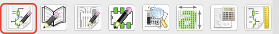
Adding Pins
We don't yet have a body built for our chip, but we're going to add pins.
Select the "Add pins to component" icon. Click on screen where you want each pin to be placed.
Add a name and number to the pin.
Line up the input pins on the left side. Output pins on the right. Power (Vcc/Vdd/Vdd_IO/...) on the top. Ground/sink on the bottom.
"Orientation Right" is for pins that will be placed on the left side of the chip.
"Orientation Left" is for pins that will be placed on the right.
Repeat for all of your pins.
Draw the Chip Body
With all of the pins lined up nicely, use the "Add graphic rectangle to component body" icon.
Click once to start drawing the rectangle, and once more to end the drawing.
You should now have something like this...
Save Your Component
Click "save current component to new library"
And now you can close the editor window.


 bobgreenwade
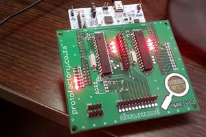
 Tom Van den Bon
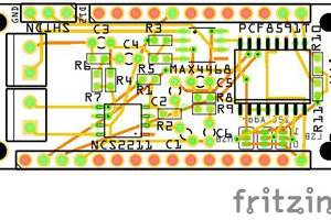
 OzQube
IIRC, Blitzortung uses GPS to synchronize time, with each station having a GPS receiver. It would increase the cost but it would probably work very well and easily.