 Sarah Petkus
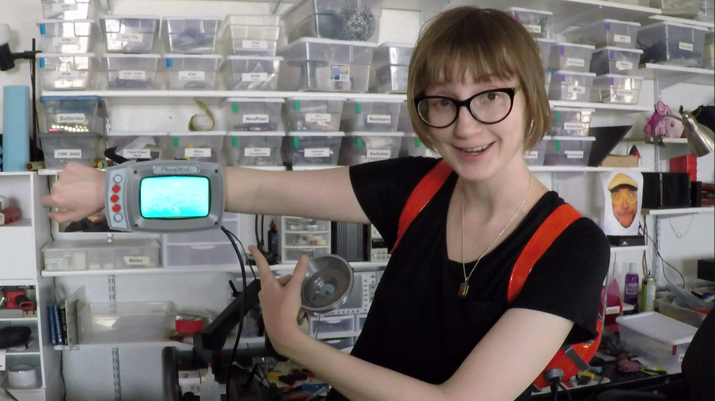
I made a status indicator that notifies me of my body's relative state of arousal!
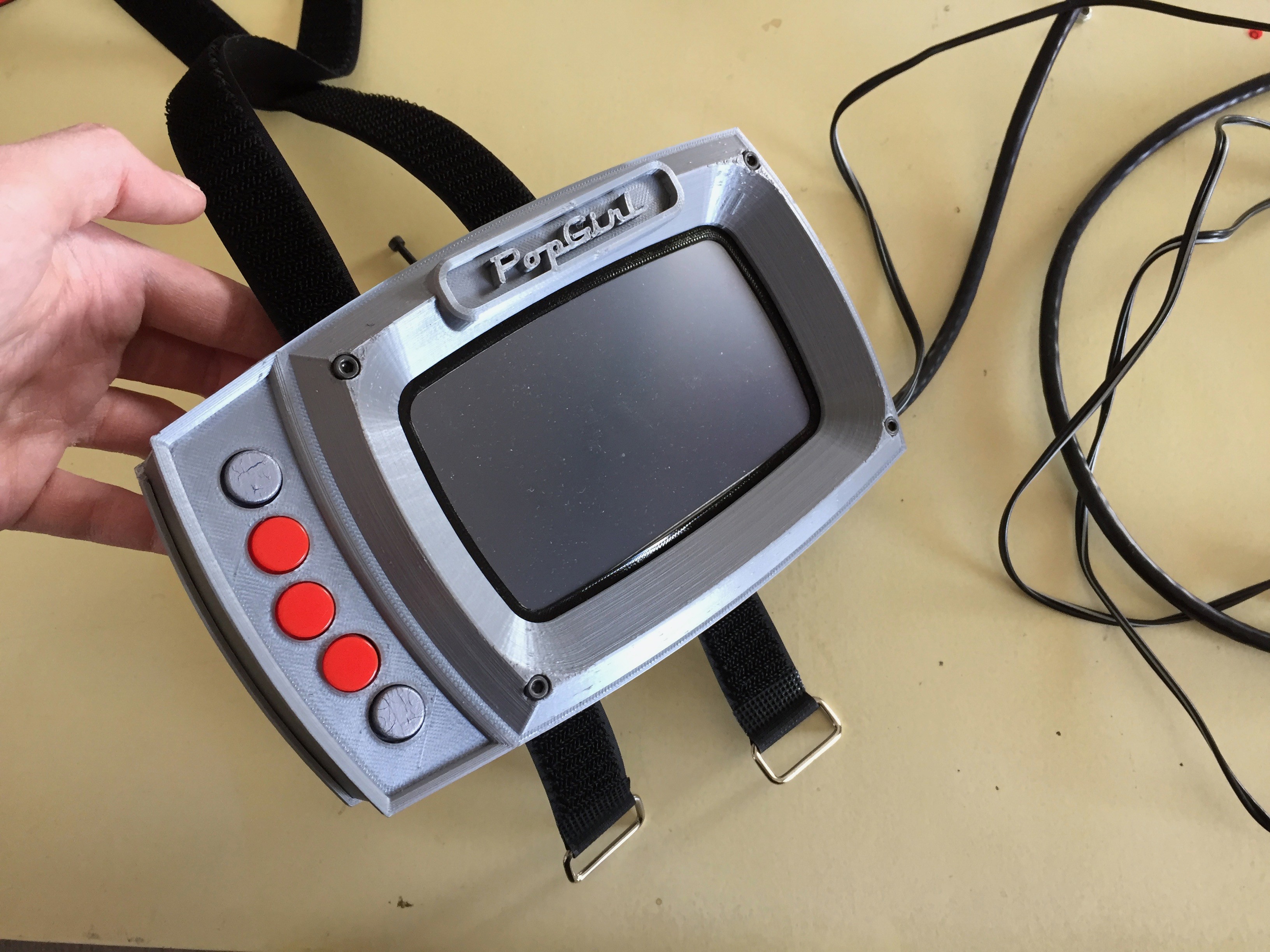
To help me visualize what's going on with the myriad of wearables I have set out to don at once, I've created an arm-mounted screen display that will tell me what I need to know at a glance.
The development of this little treat was of course a matter of hardware design and software development, so I'm breaking the build log into two parts. This first edition will cover the physical components, like the electronics, the enclosure for the electronics, and any other bells and whistles I needed to create to make it do.
BILL OF MATERIALS
Electronics stuff:
- 5" Raspberry Pi Compatable Touch Screen
- RaspberryPi Zero
- 5V, 5A Step-Down Voltage Regulator
- Logic Level Converter Bi-Directional Module 5V to 3.3V
- Round Push Buttons
- 1' HDMI cable
- Perf Board
- Stranded Wire
HARDWARE SIZES:
OTHER THINGS YOU'LL NEED:
- soldering iron
- access to a 3D printer
- filament in cool colors
- metric screw driver
- pliers
- sleet plastic (up to 1/16 inch thick)
- patience*
*I say you'll need patience, but really... you will need to perform some light modification of some cables in order to get them to fit within the profile of the enclosure. Specifically, you'll need to strip some of the casing from a USB mini cable, as well as strip the plug casing from an HDMI cable. =O
We'll talk more about that later.
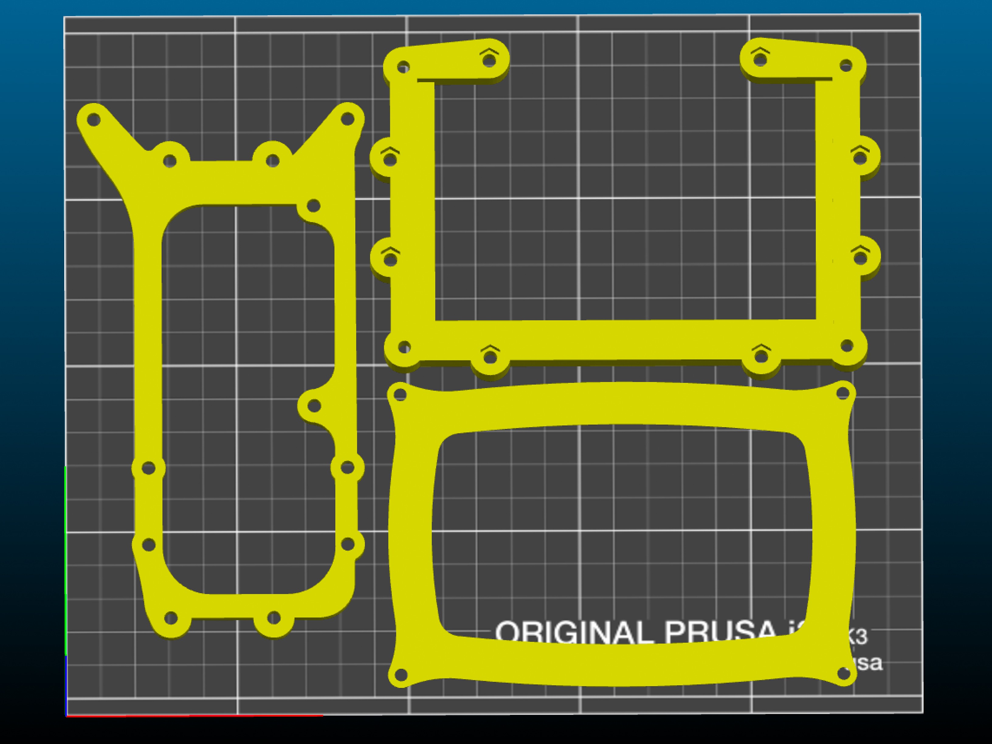
THE PRINTED STUFF
You'll be glad to know that there are only 5 core pieces you'll need to print in order to make your own POPgirl enclosure.
The .stl files can be found on my SHE BON gitHub repo!
The bad news is that a couple of them will take close to six hours to print a piece.
Stylistically, I chose to print the enclosure in silver and black... but you can use whatever colors of filament you'd like, of course. Here are the two trays of parts according to the color they'll be represented as in these build instructions:
SILVER PARTS:

- face_plate (~7 hours)
- arm_mount (~8 hours)
BLACK PARTS:
- PCB_mount (~1 hour)
- screen_frame (~2 hours)
- screen_gasket (5 minutes)
SPACERS:
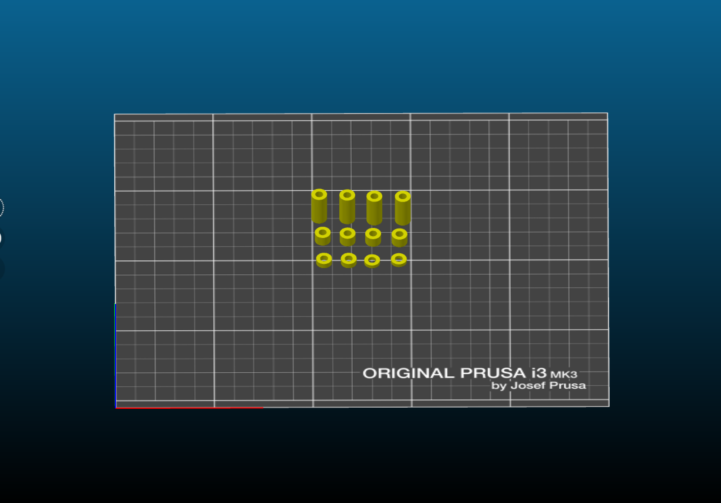
In addition to the primary pieces, there are some super important spacers you'll need to print. I chose to print them in red, so they're easy to spot in case they roll off the table into the forever carpet.
The other important thing to note at this point of the build, is the length of hardware that goes with each space. This is key, because the screw length must be such that it is long enough to reach the countersunk nut it is being screwed into, but not too long otherwise it will bottom out (or poke a hole through the enclosure)
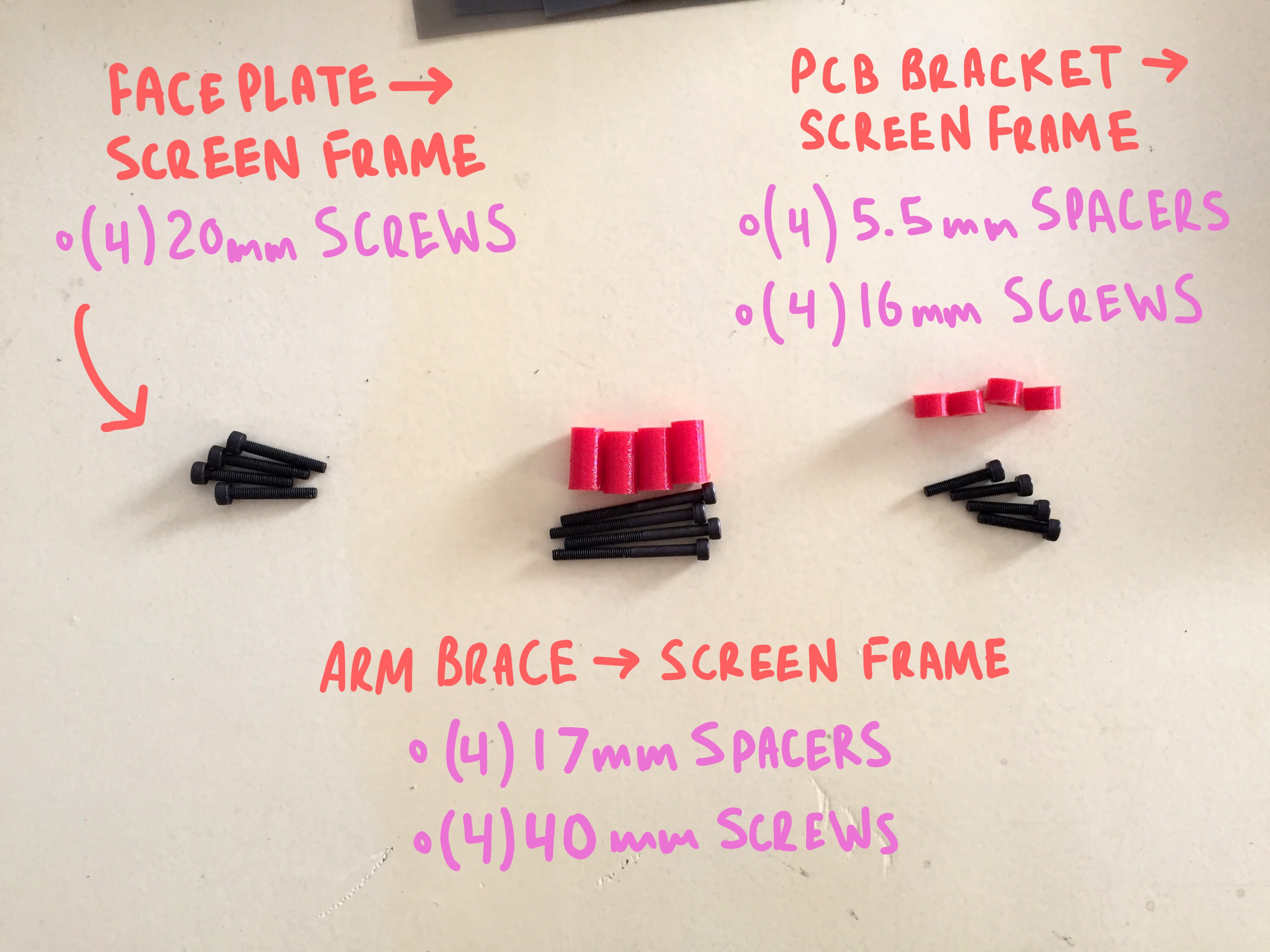
- (4) 5.5mm
- (4) 17mm
- (2) 2mm
- (2) 3mm
CAPTURING THE SCREEN
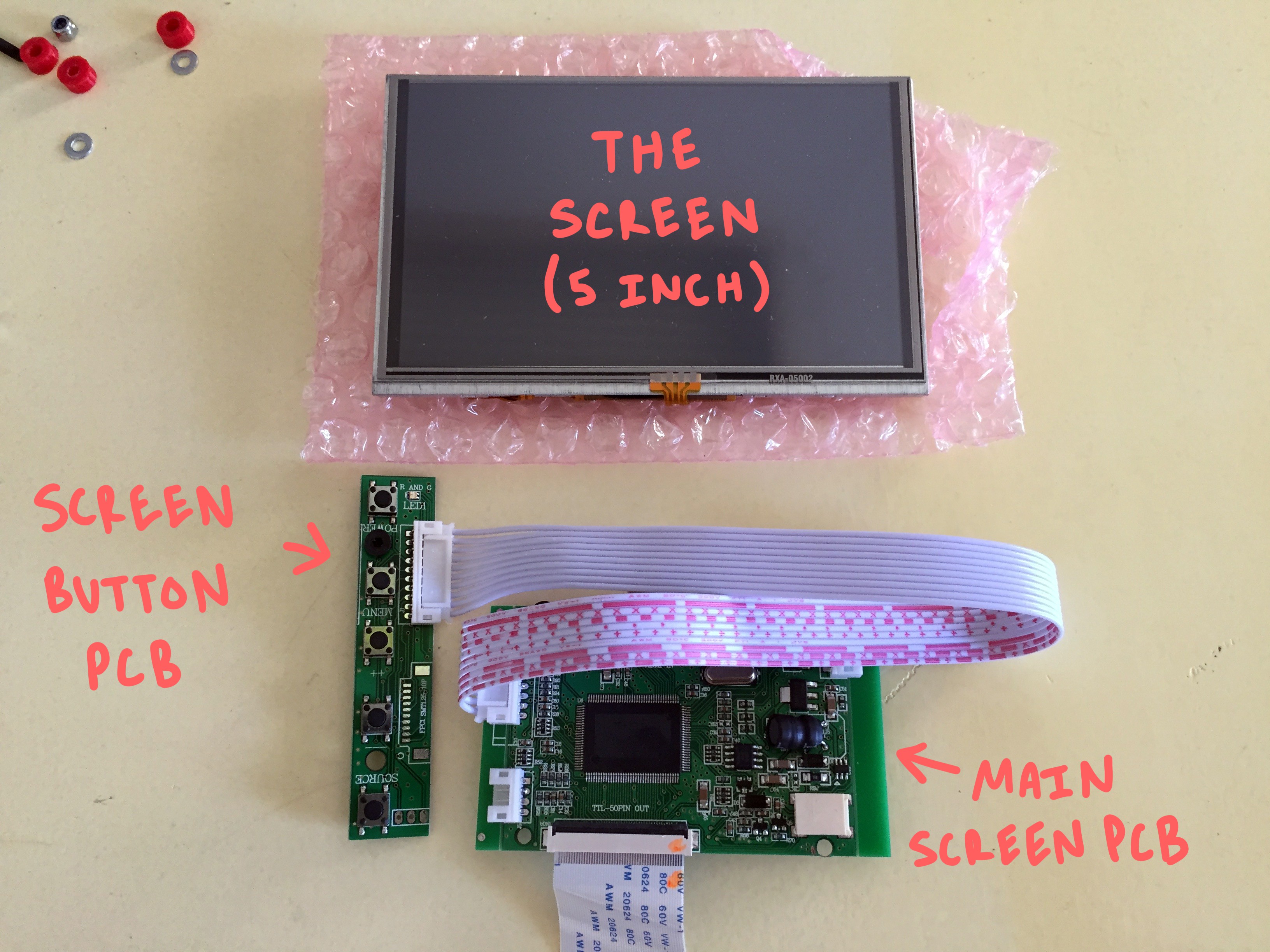
This entire build is constructed around a 5" touchscreen monitor which you can pick up from AdaFruit for ~$80. It's a little awkward to use, as it comes with three horrible PCB tumors hanging off from it at odd angles... but if you take care to secure them in place when you get it, they aren't the worst to work around.
Right away you can disconnect the ribbon between the screen itself and the main PCB, and also unplug the button board all together, as we won't be using it.
The other helpful thing to do as soon as you unpackaged your screen is to use some double sided silicone tape to adhere the thin and fragile touch-screen PCB directly to the back of the screen to keep it from flopping around all loose-like.
Just tack it down where it wants to lay naturally, and you should be good.
Take the "screen frame" and press-fit some nuts into all of the counter-sunk pockets. There should be (8) on the front, and (4) on the back.
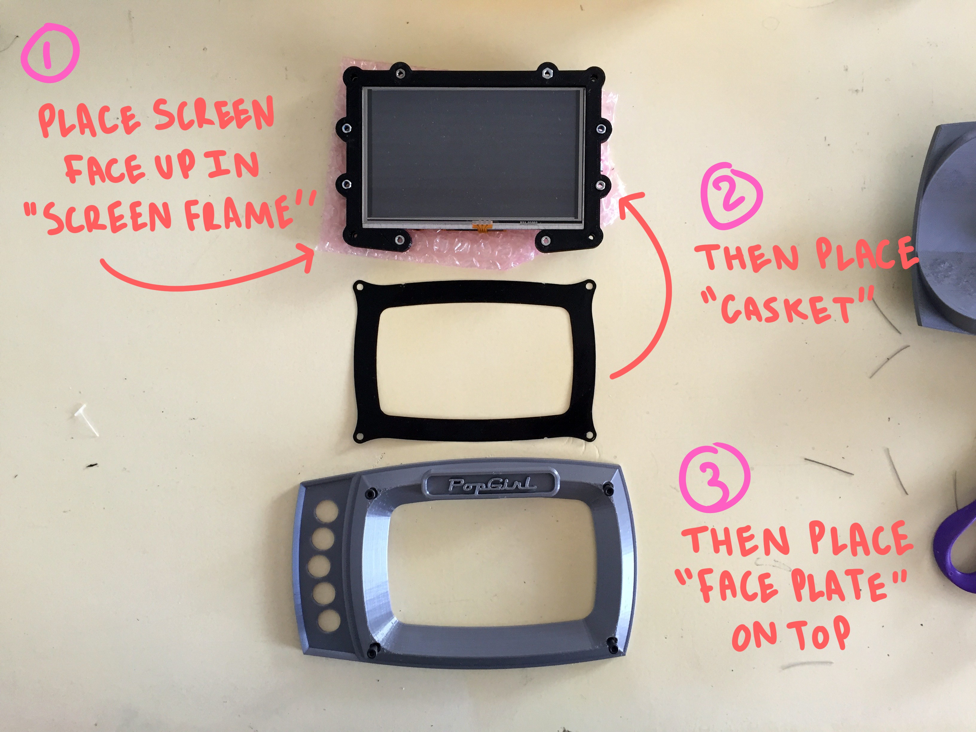
Then lay the back on the screen into the frame so that its front is unobstructed and flush with the printed plastic:
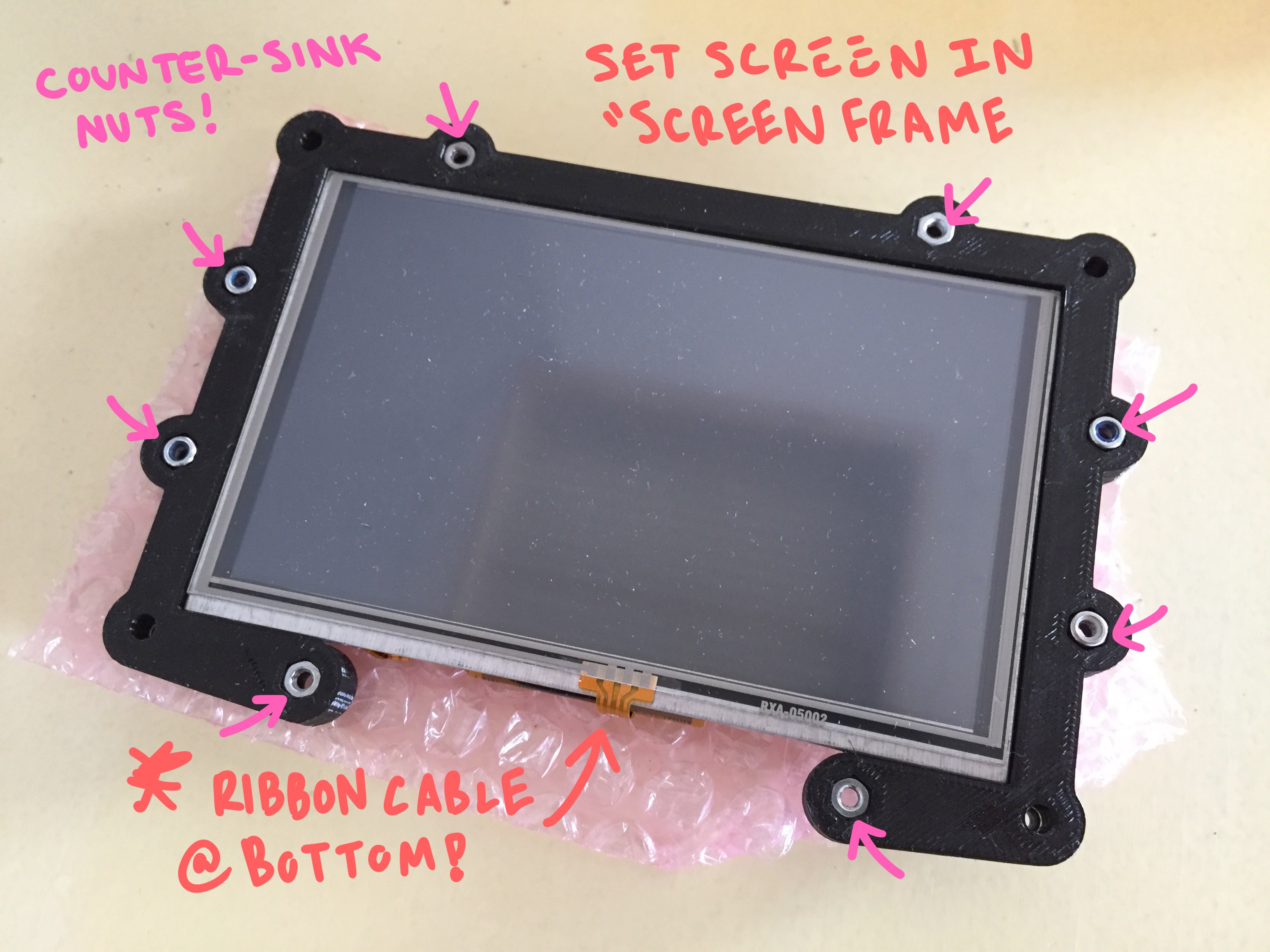
next, place the thin gasket on top of the screen, lining up the four mounting holes at the corners. It should over-lap and frame the touch-area just slightly.
Lastly, the big dance "faceplate" piece should mount directly on top of the gasket. Like up the same hole along the four corners.
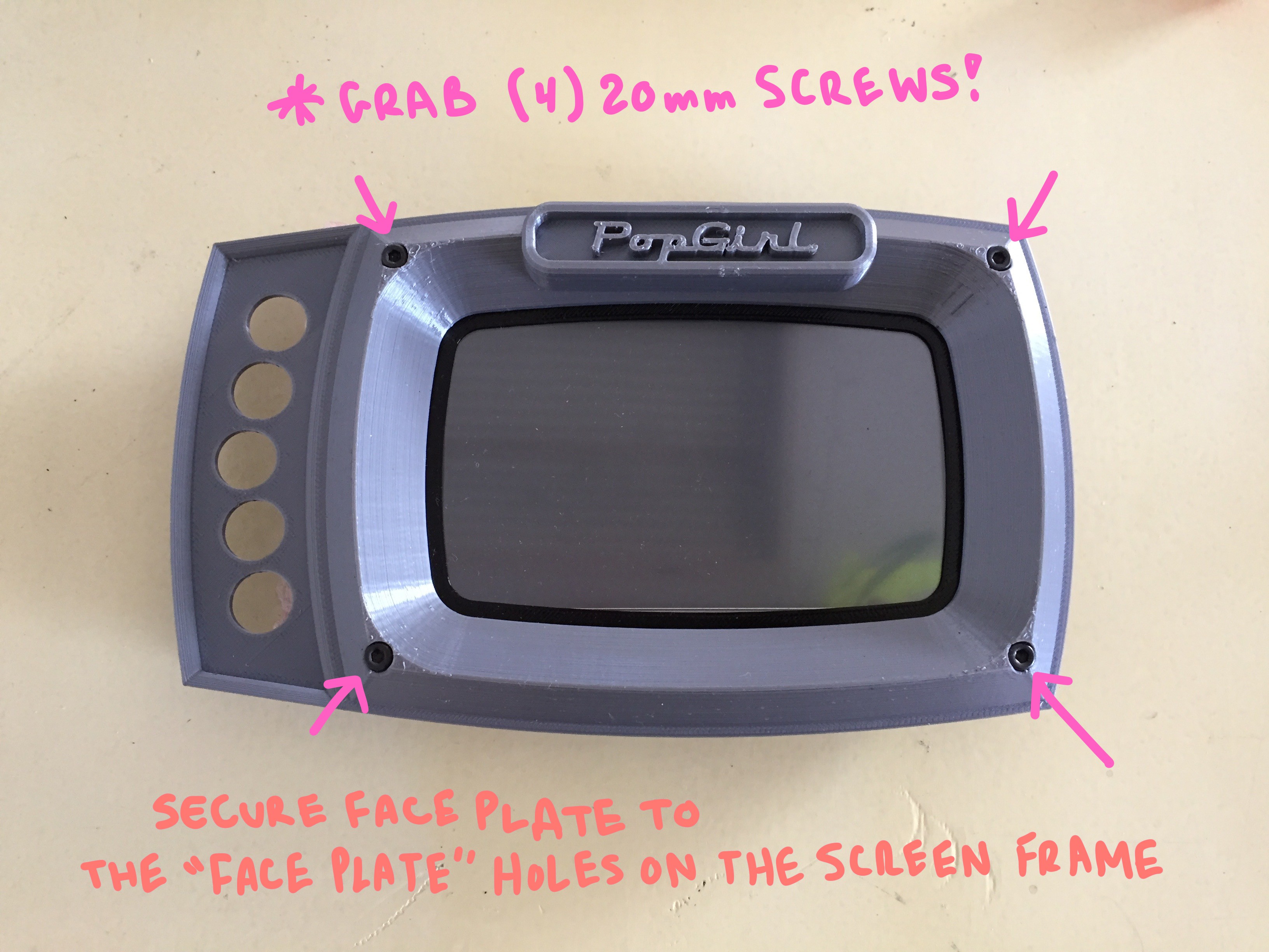
one these three pieces are sandwiched together, you can thread (4) 20mm screws through the from of the "Faceplate" into the corresponding counter-sunk nut holes in the "screen fame":
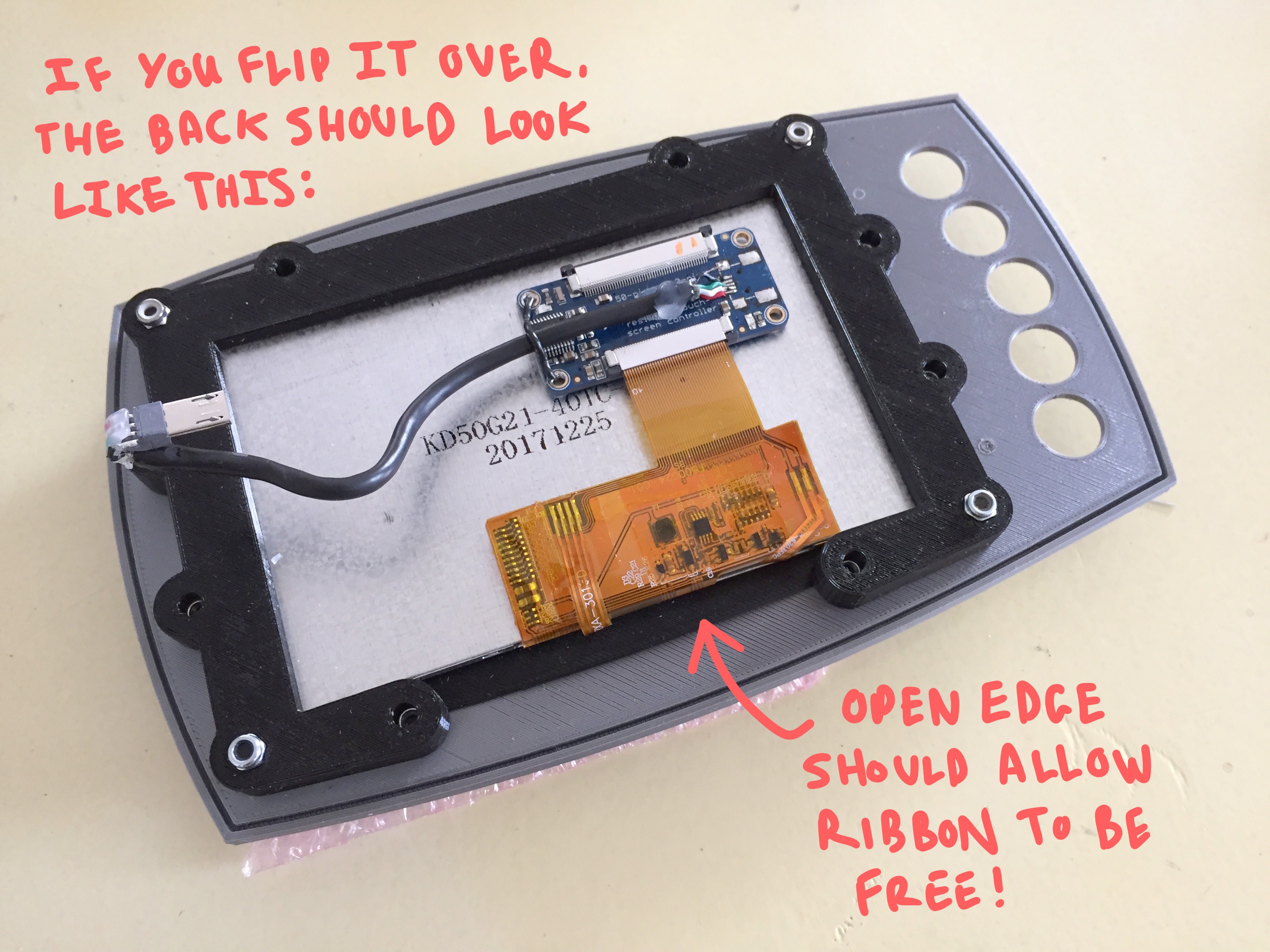
The back should now look like this, with both the ribbon cable and the open edge of the "Screen frame" facing the bottom edge of the assembly:
MOUNTING THE PCBS TO THE "PCB FRAME"
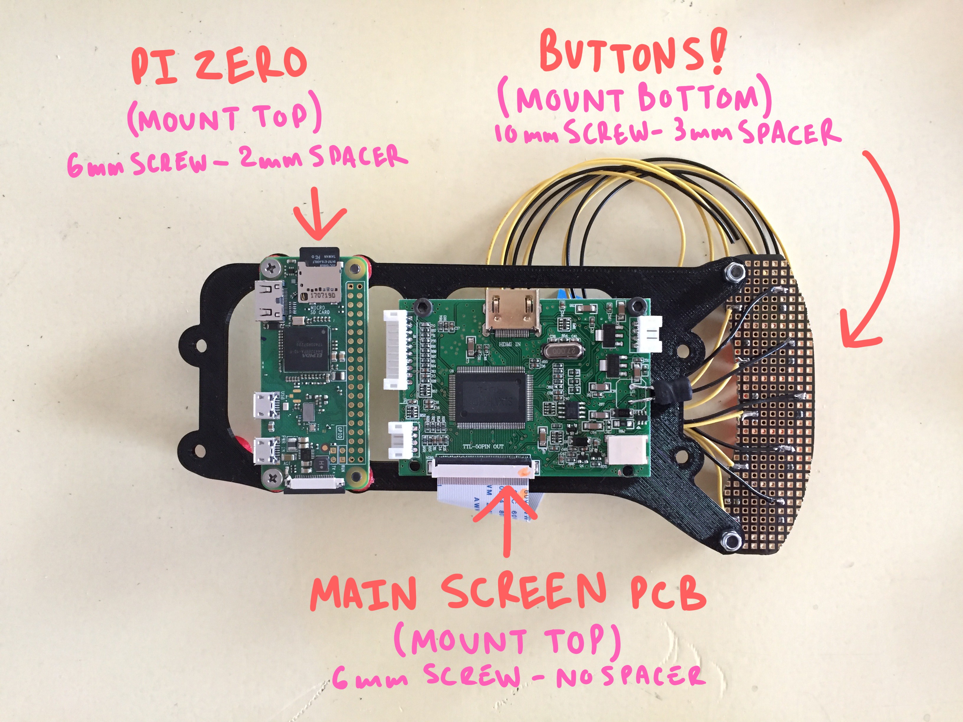
There are three circuit boards that will all share a single mounting frame. On the far left, there should be your "Raspberry Pi Zero", in the center will mount the screen's "primary board", and on the right will mount a "custom button board" that you'll need to put together with some perf-board and those tiny push buttons I listed on the bill of materials.
The completed board should look like this once completed:
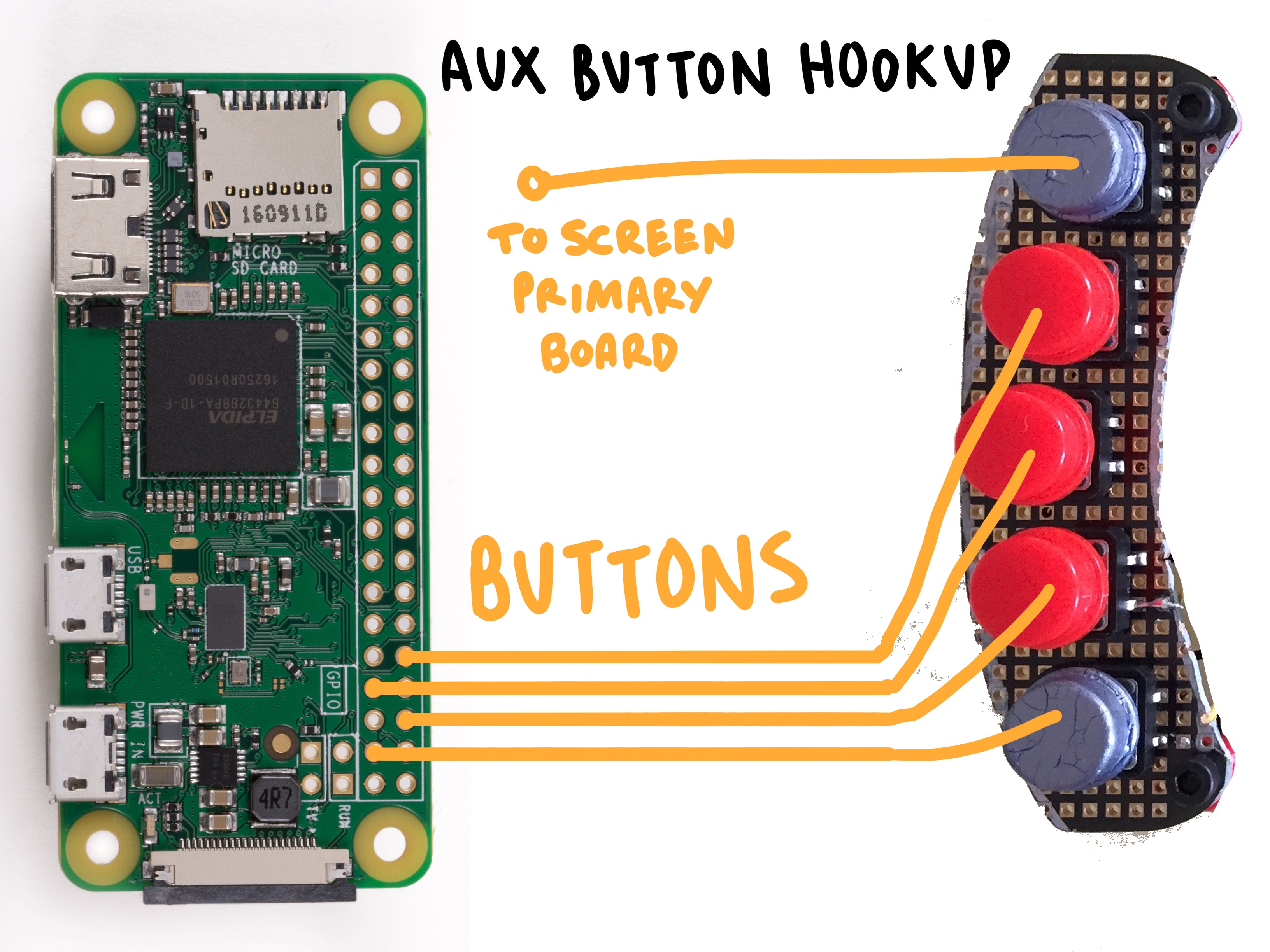
MAKING A CUSTOM BUTTON BOARD
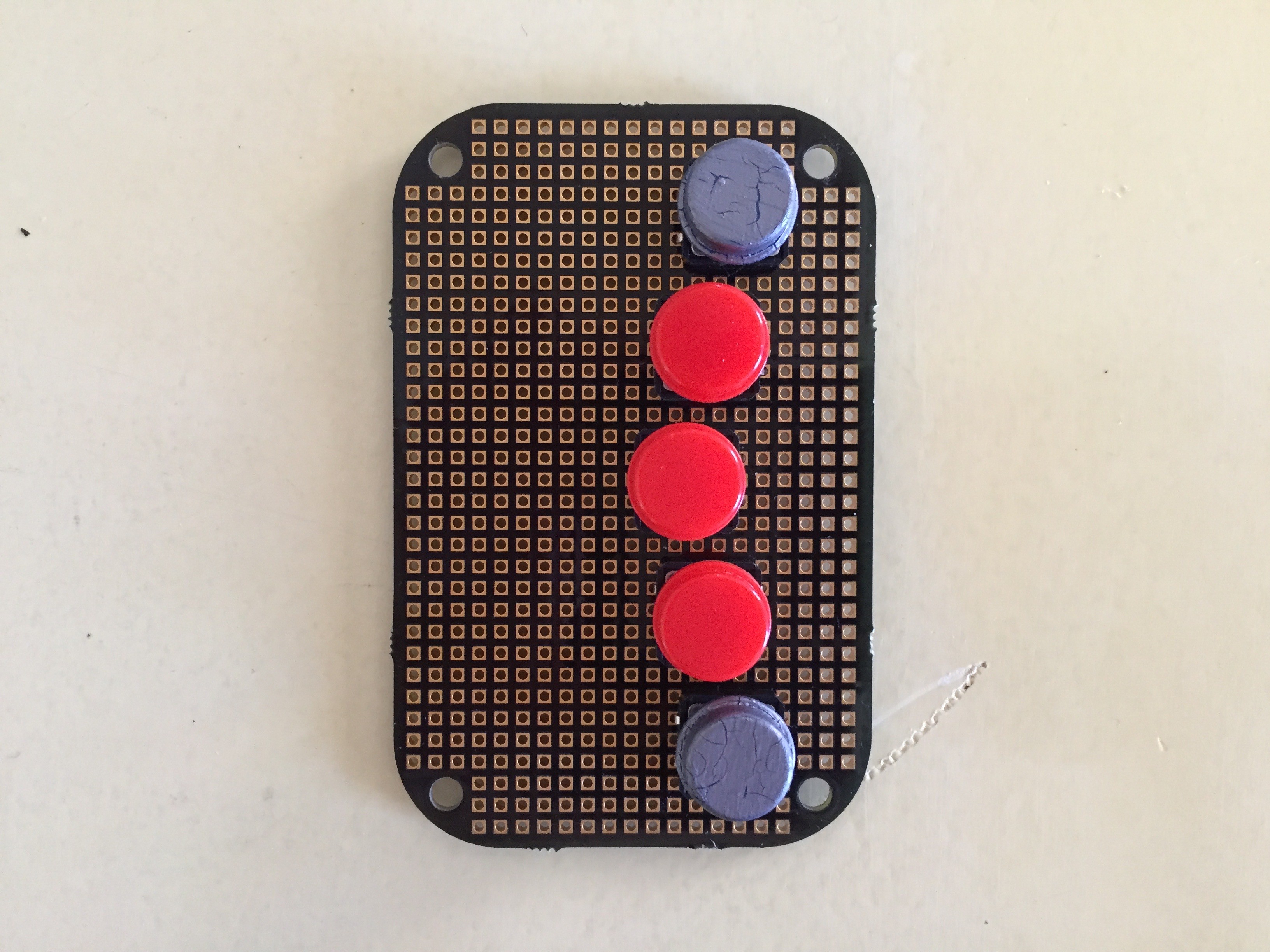
You will need to solder up a quick button board module specifically fit to the clearance holes in the face plate!
Don't worry! If you have standardly spaced perf board, then you're all set. The front of the board should look like this. Five buttons, staggered by one row in a slight bow to the left:
Here is a diagram for the dimensions and space of the buttons as they should fit into the perf board:
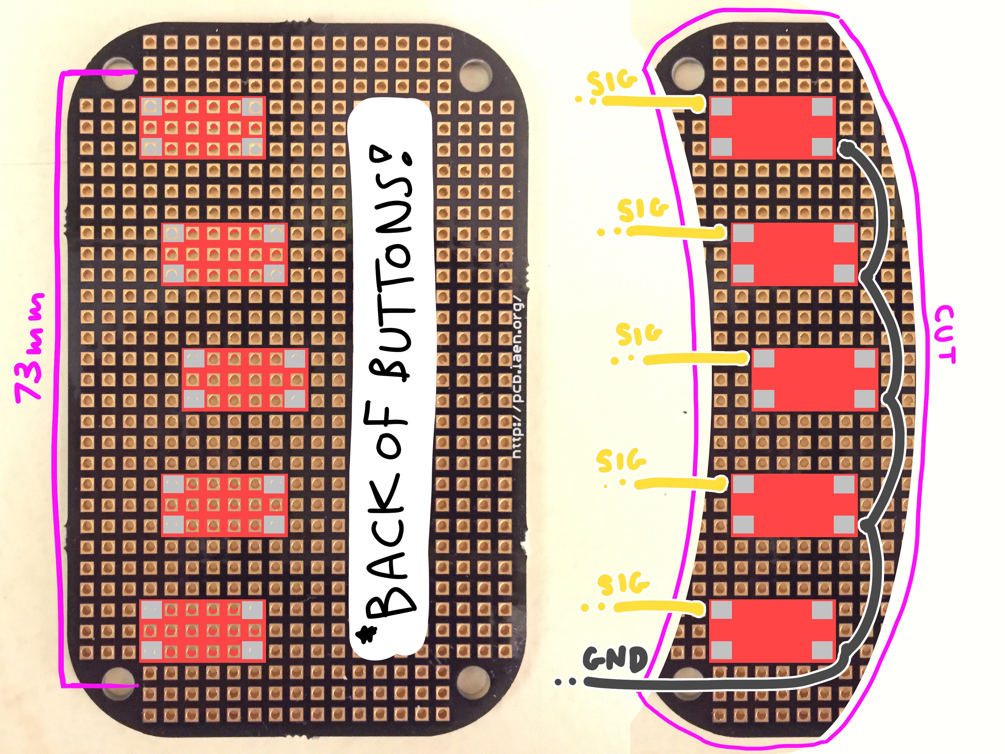
There should be a wire coming off from each button that is ~7" long... and at least on ground wire!
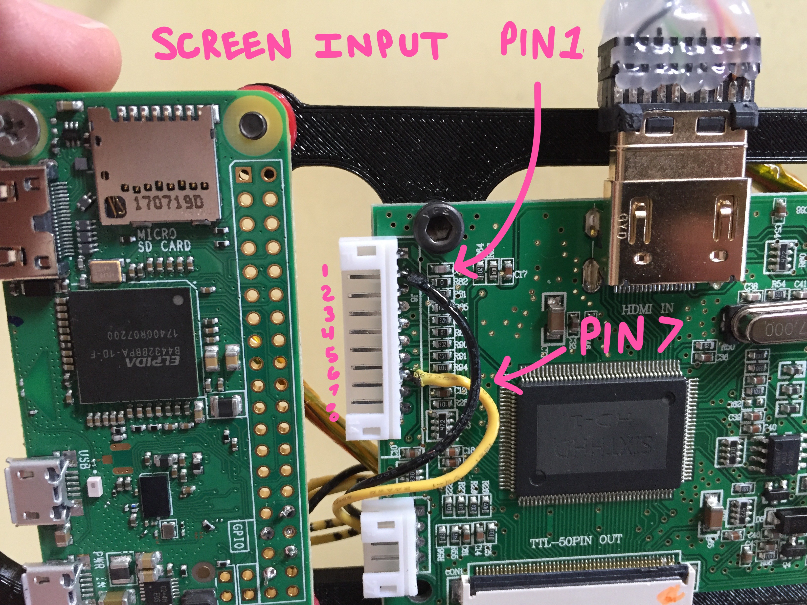
One of your buttons should connect to the "INPUT" of the screen, so that just incase the screen doesn't boot up in the correct mode, you'll be able to easily change it without needed to hook up the whole button bar tumor which came with the screen.
Pick a button, and wire to the pad leading into these two pins of the "button board" connector on the screen's "primary board":
The rest of the buttons on your "custom button board" can be wired into any input pin you'd like on the Raspberry Pi Zero. I personally chose these four pins on the pi:
CONNECTING THE PCBs TOGETHER
This part kinda sucks. :)
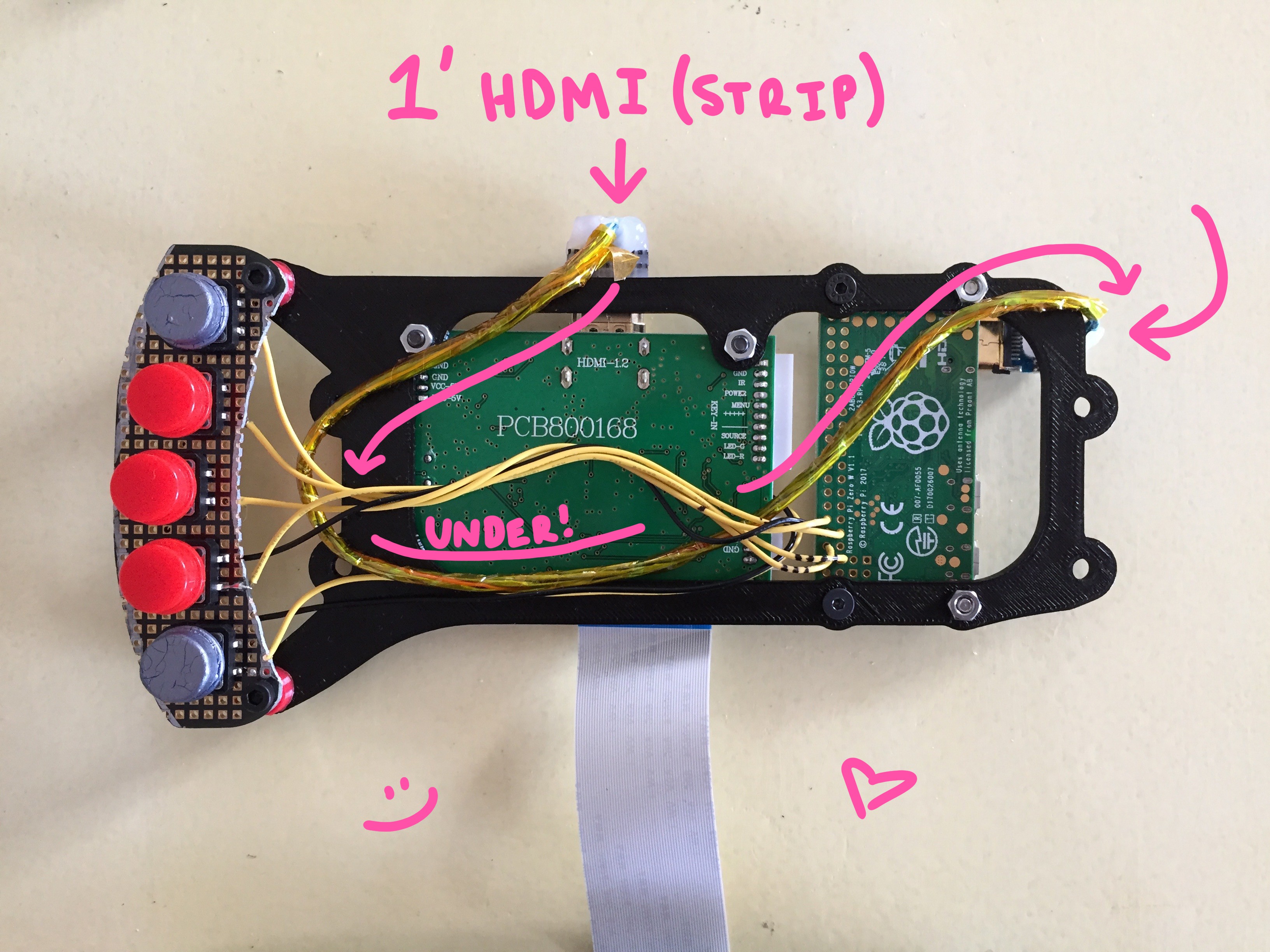
You will have to run *specifically* a 1' HDMI cable from the screen's "primary board" to the "Raspberry Pi" - but in order to get it to fit within the enclosure, you will have to skin it completely. (I will soon post a stream of Mark demonstrating how to do this)
The fully skinned HDMI cable should be routed as such:
There are eight remaining empty holes on the "screen frame" that will be used for attaching this PCB bracket, as well as for sealing up the enclosure.
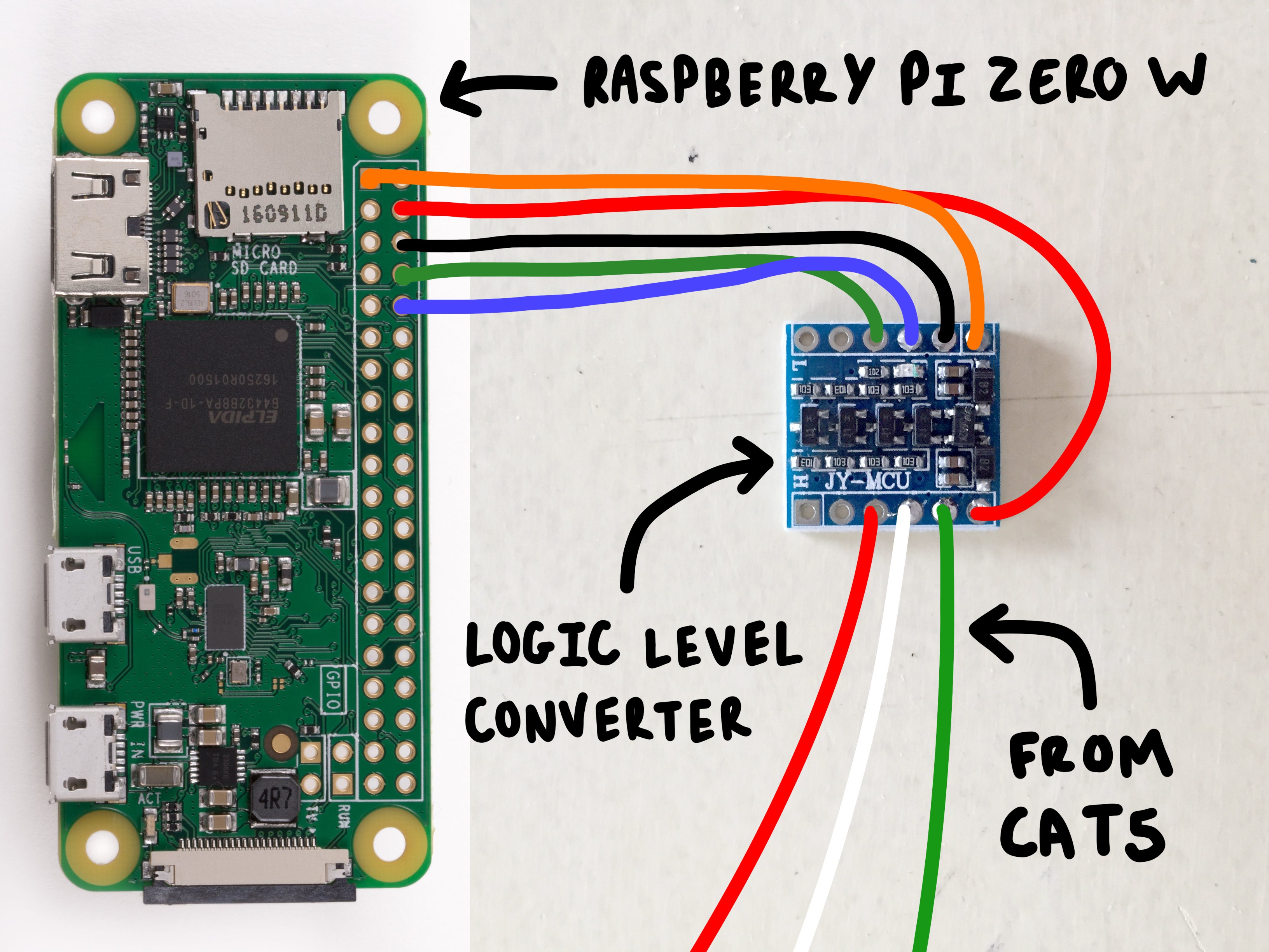
ATTACHING THE LOGIC LEVEL CONVERTER
Floating inside of your enclosure, there will exist two voltage regulators. One is a logic converter which drops 5V to 3.3V, there other is for the system in general.
The main voltage converter is available from Pololu.com, and will go between your power supply and the system at large:
The logic converter is available on Amazon and will go between the Pulse board and the POPgirl's Raspberry Pi Zero board. The stripped end of your cat5 cable will attach to this board, as well as some wire going to your raspberry pi. The hookup will look like this:
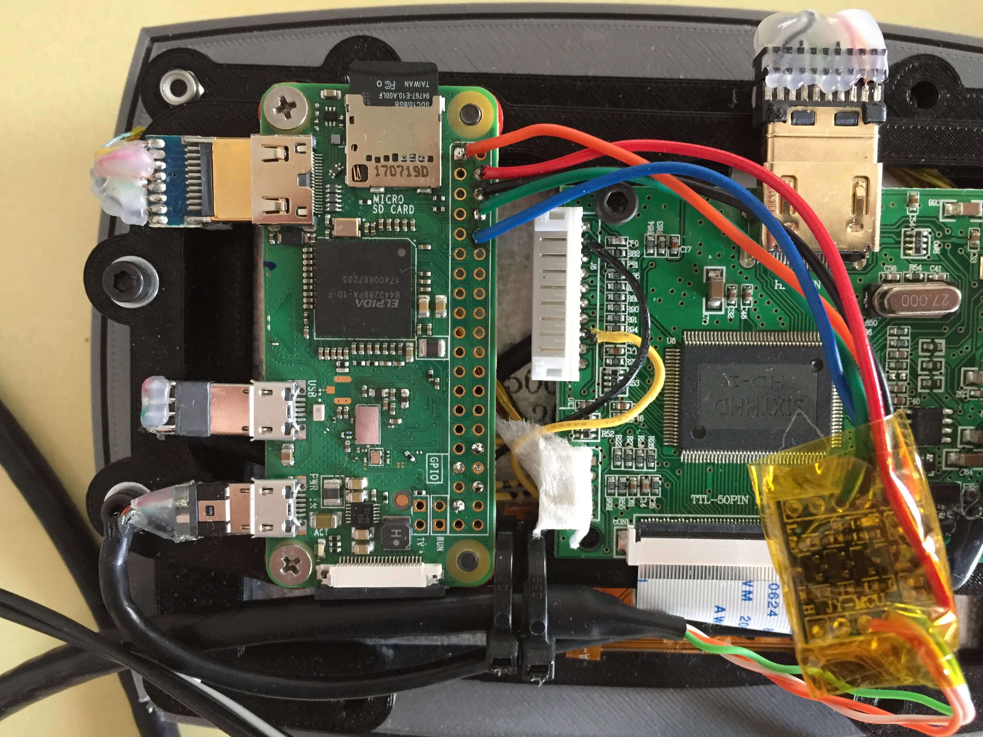
Once its connected, wrap the module in some capton tape and let it rest over the middle the screen's "primary board" like a little floaty tumor:
ATTACHING THE VOLTAGE REGULATOR
The next tiny glad that you'll need to prepare is the "voltage regulator". You can read more about it on Pololu's specs page!
The cable from your chosen power supply should connect *in* to the board, and the male connector compatible with the screen's "primary pub" should be running *out* from the board:
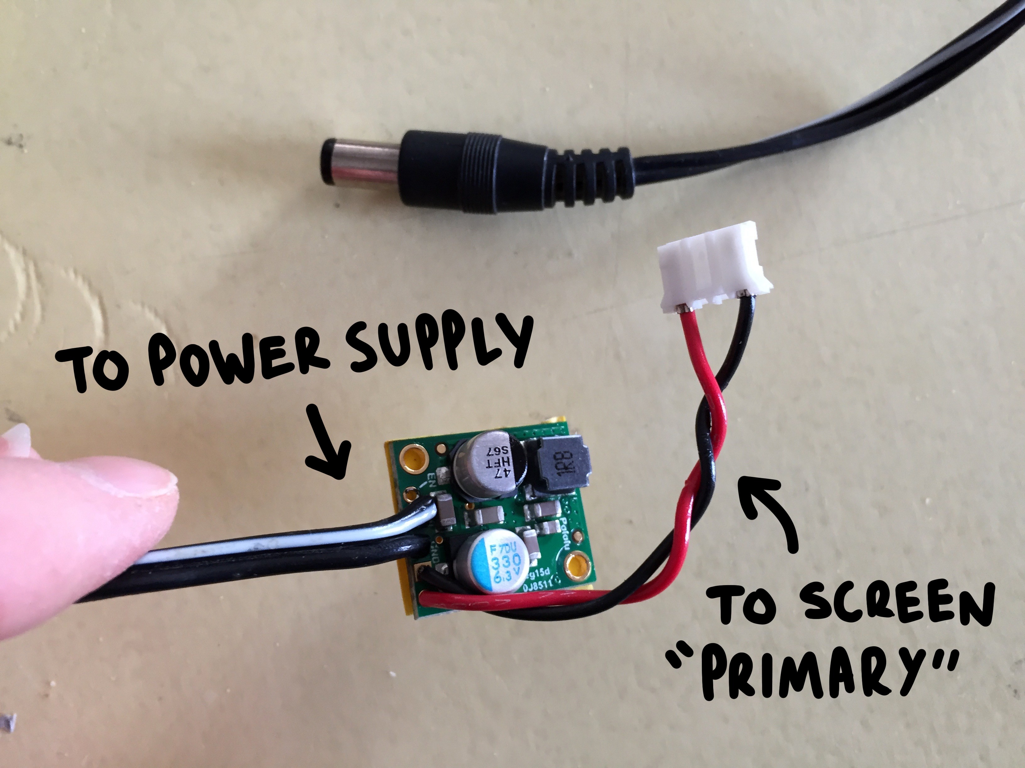
Place some electrical tape along the back of the board and wrap it in capton tape to protect it, as this module will more or less "float" inside of the enclosure like a rogue organ:
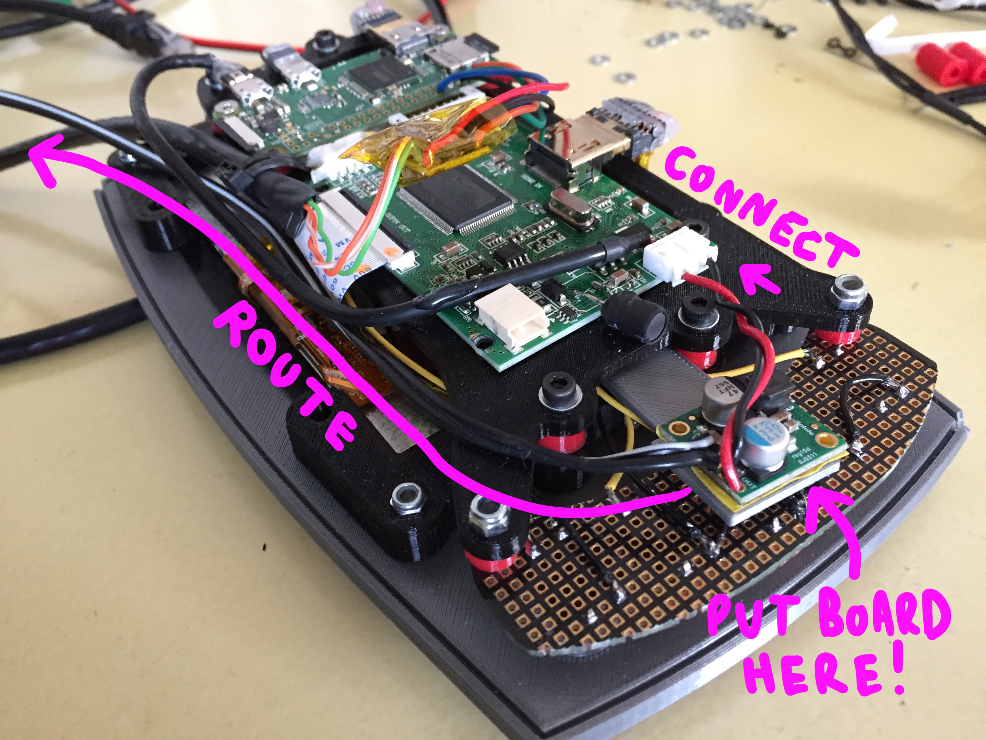
The cable running *in* from your power supply should rout along the bottom edge of the enclosure next to the CAT5 data line.
ATTACHING THE *FULLY LOADED* PCB MOUNT
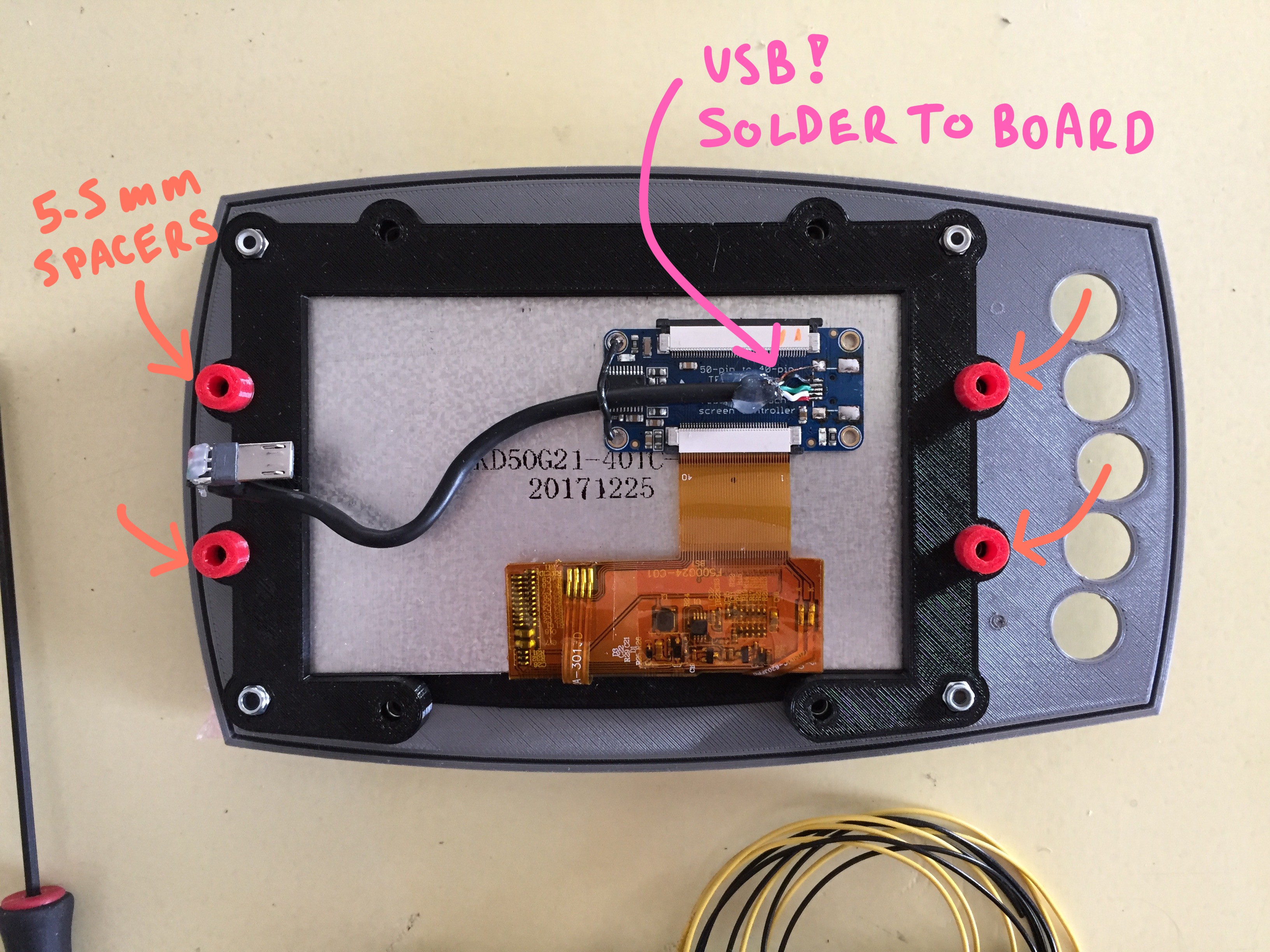
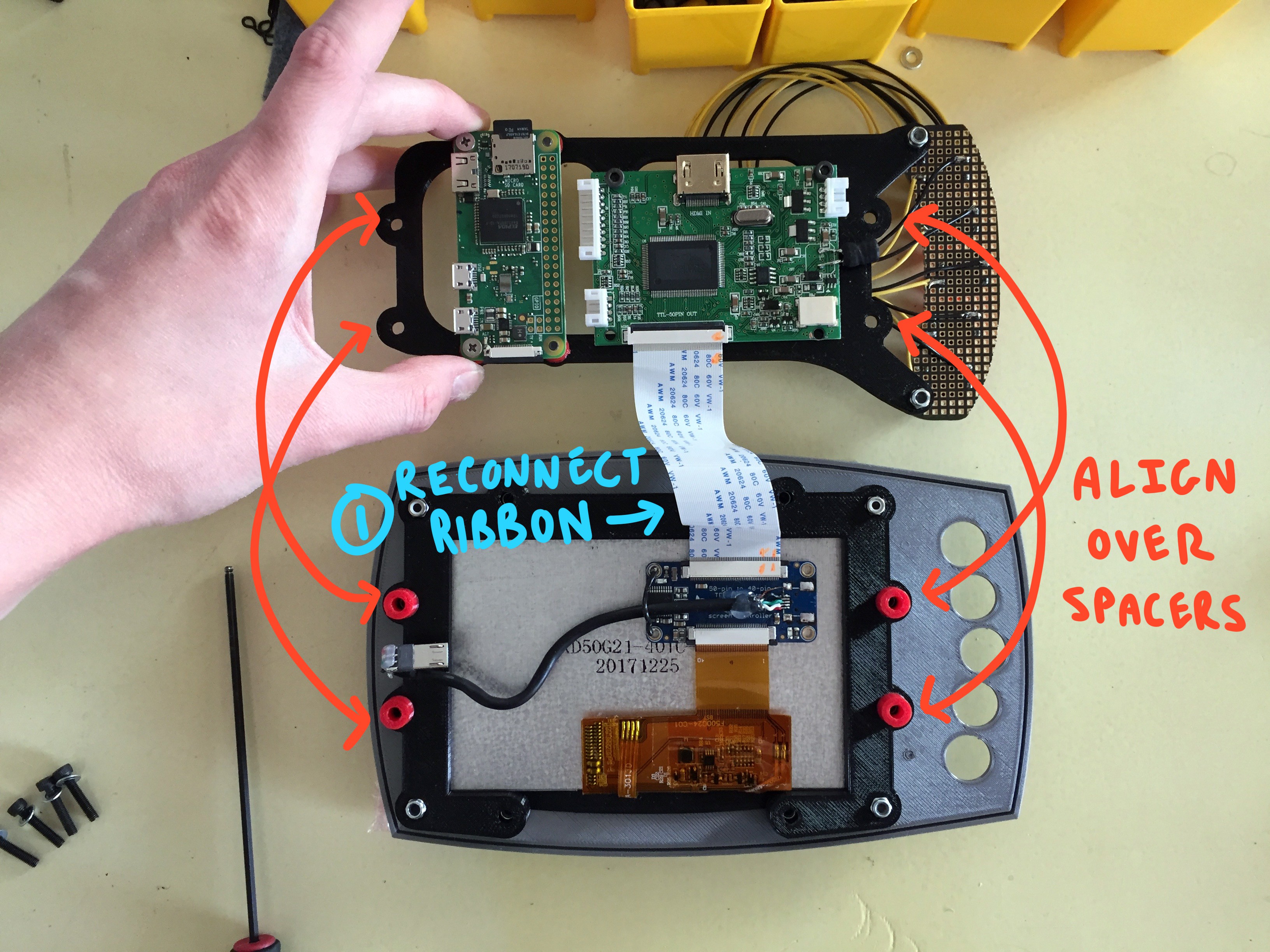
You'll be attaching your loaded PCB bracket to the four holes circled below:
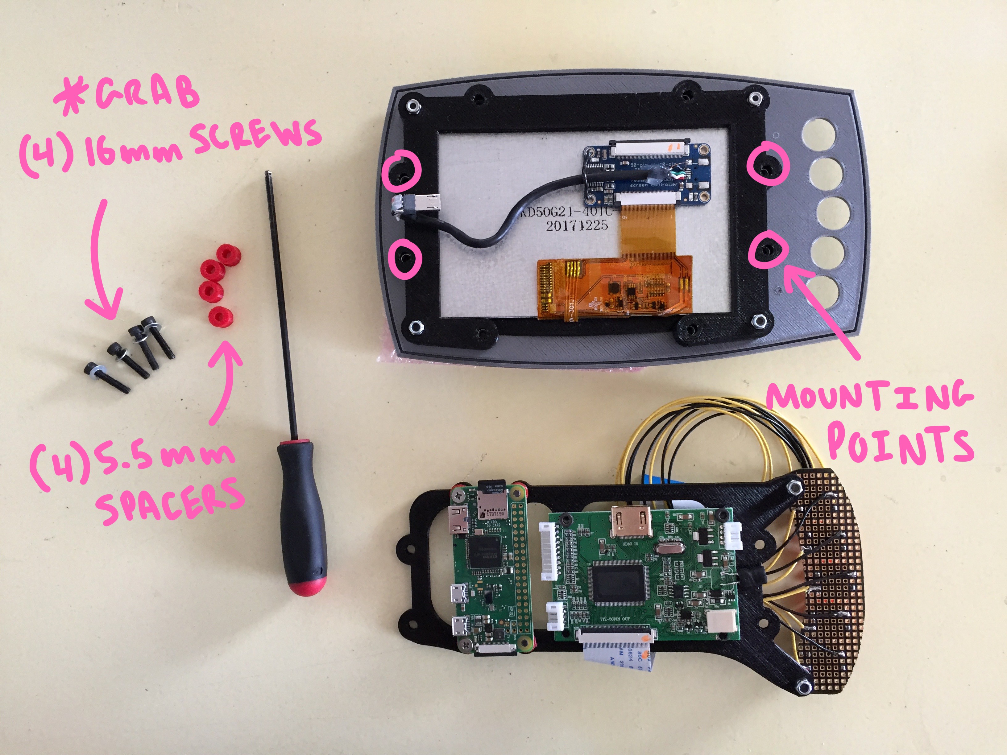
Grab your 5.5mm spacers and position them over these holes:
Be sure to reattach your ribbon cable from the touch screen PCB to the main screen board before you position the "PCB bracket" above the spacers:
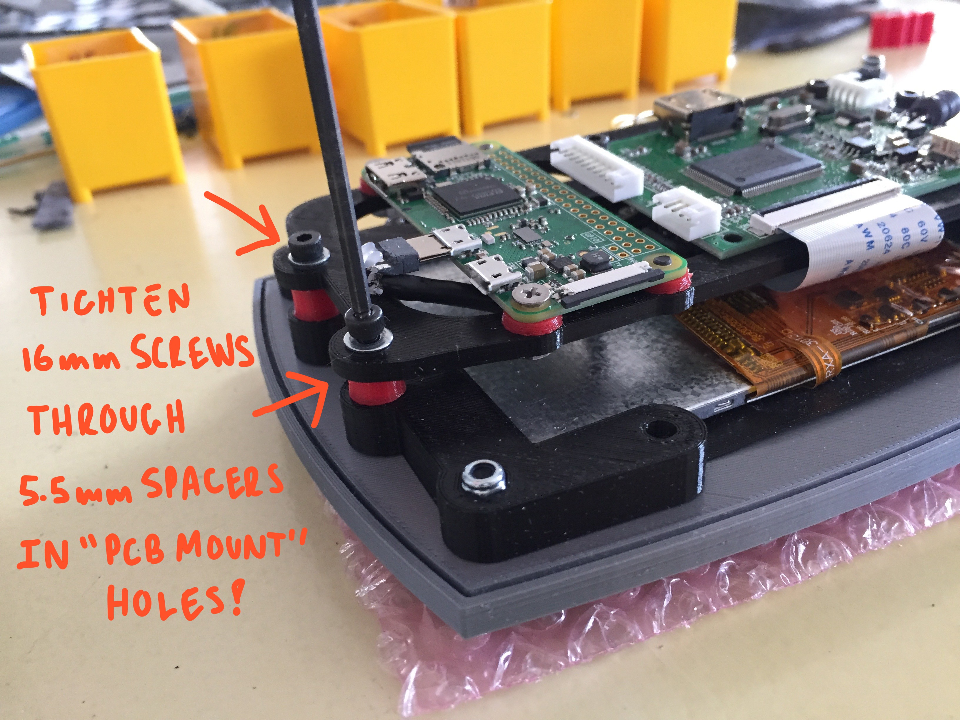
Line up the holes of the "PCB bracket" over the 5.5mm spacers and the receiving holes on the "screen frame", and thread in your 16mm hardware. It will be received by the countersunk nut inside the "screen frame":
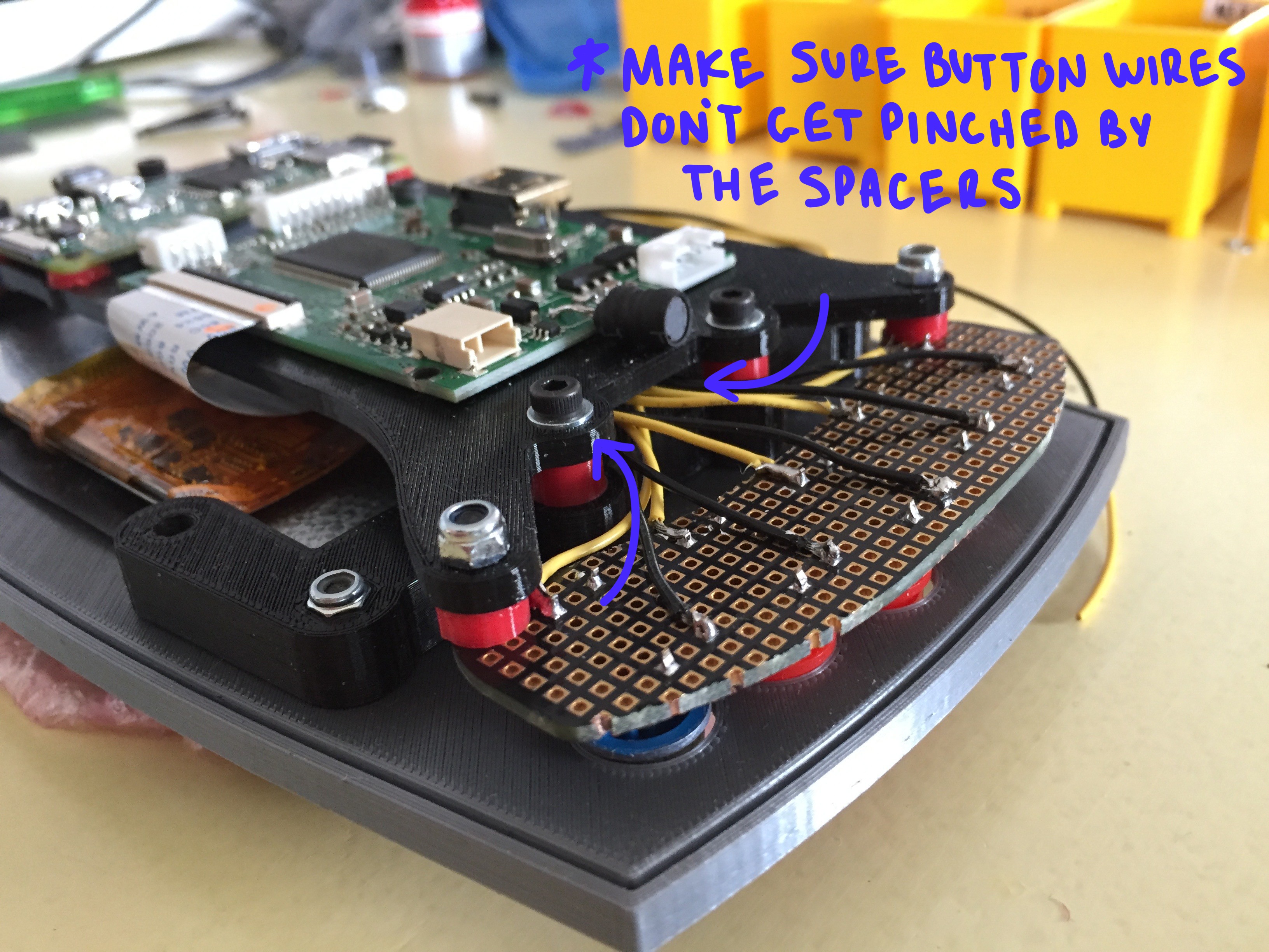
Maker sure that while you are doing this, none of the wires coming off your custom button board are being pinched or twisted strangely:
Make sure all of your cables are connected and that everything looks level and parallel. Then lay the assembly face down:
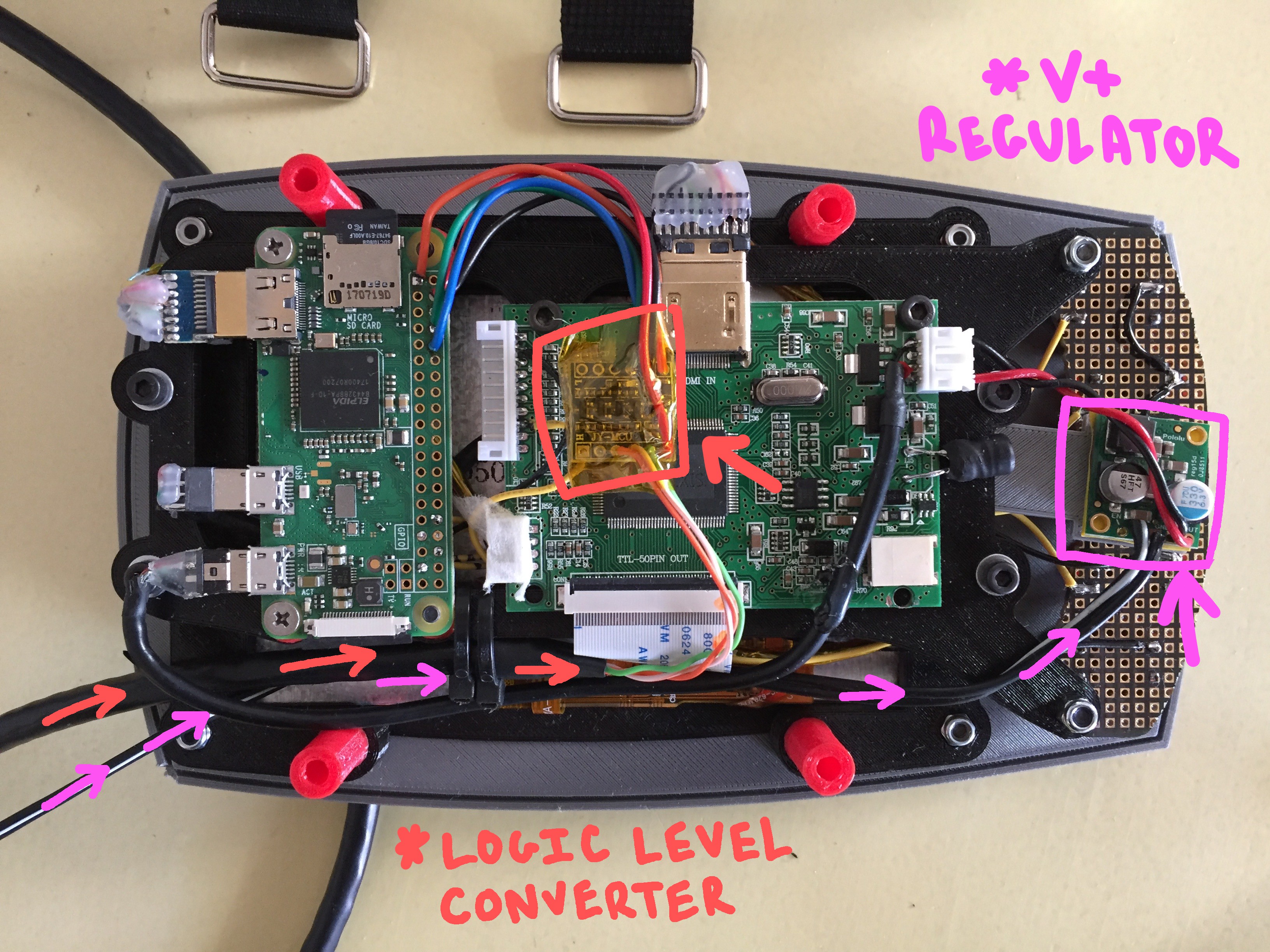
Your "logic level converter" and your "voltage regulator" should seat roughly in the areas shown above. Be sure to wrap them in protective capton tape so nothing shorts out!
ADD STRAPS TO THE "ARM MOUNT"
Before you seal everything up, you'll need to do something a little screwy with your velcro straps (something I will likely fix in a later version of this build, but for now... we'll just do the weird work around)
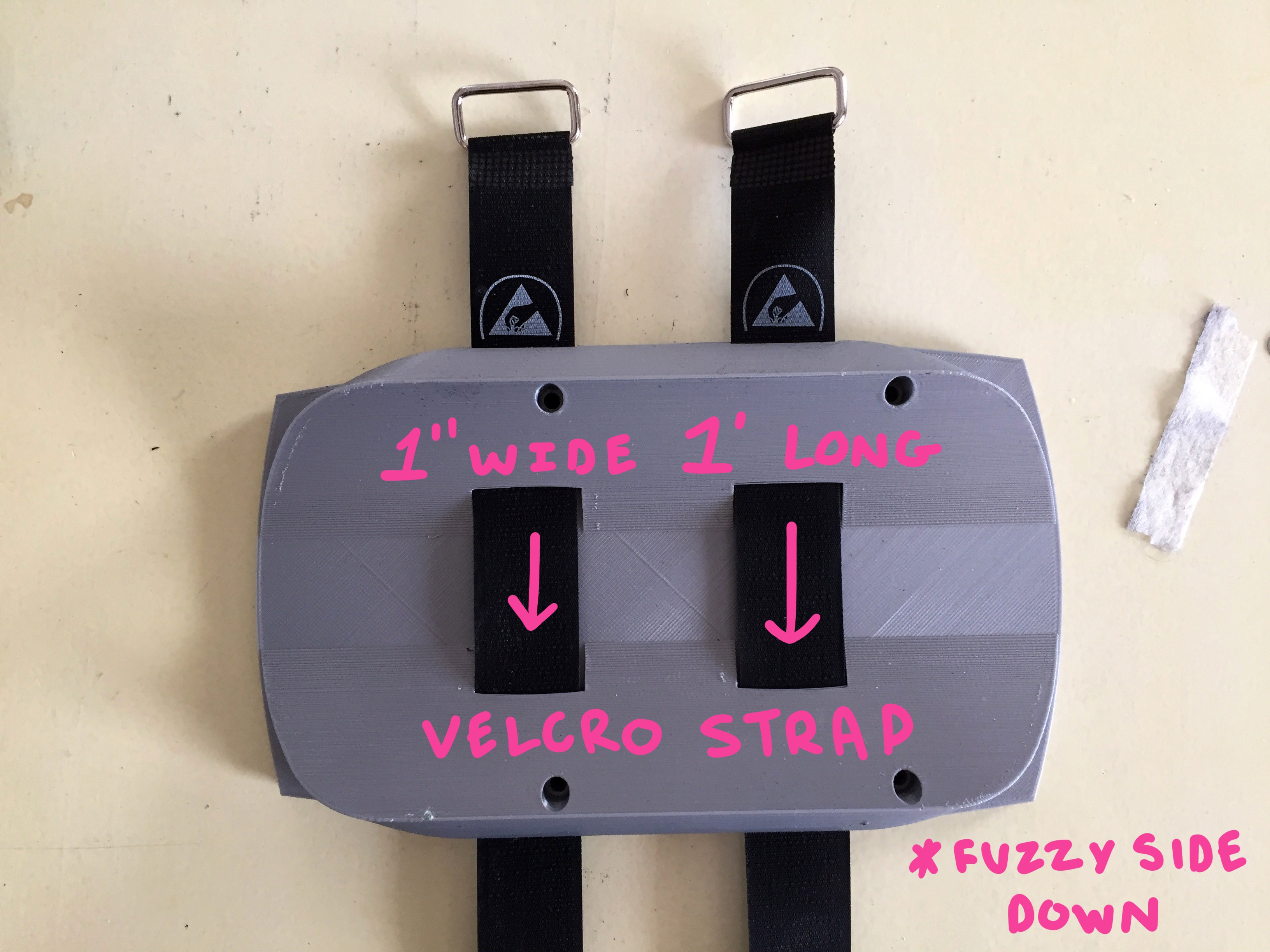
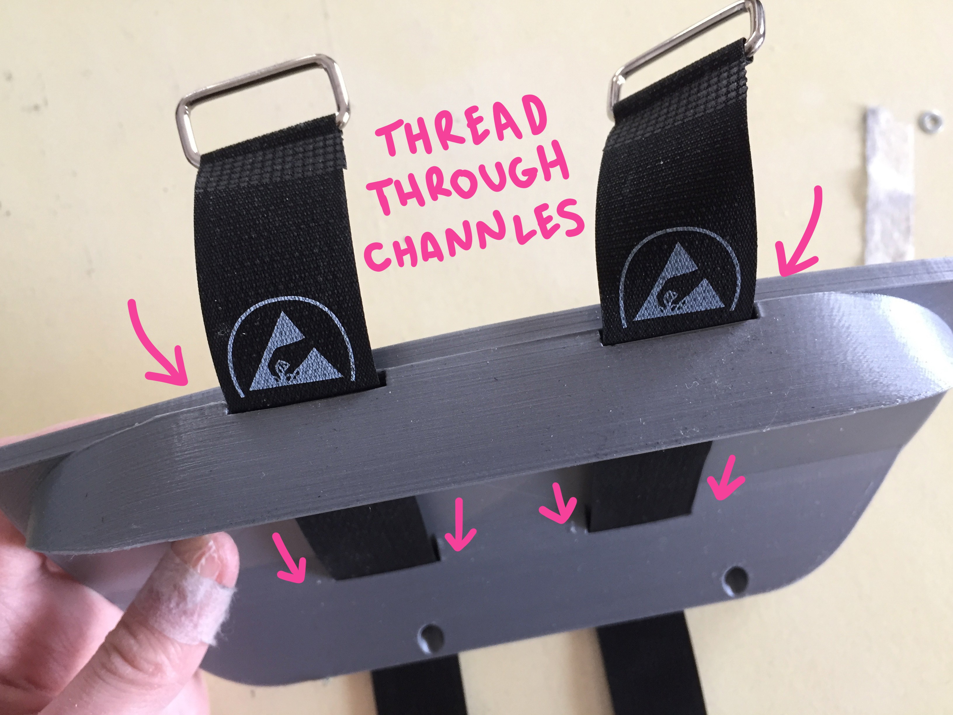
Slide your velcro straps through the flat channels in the "arm capture" piece that you printed.
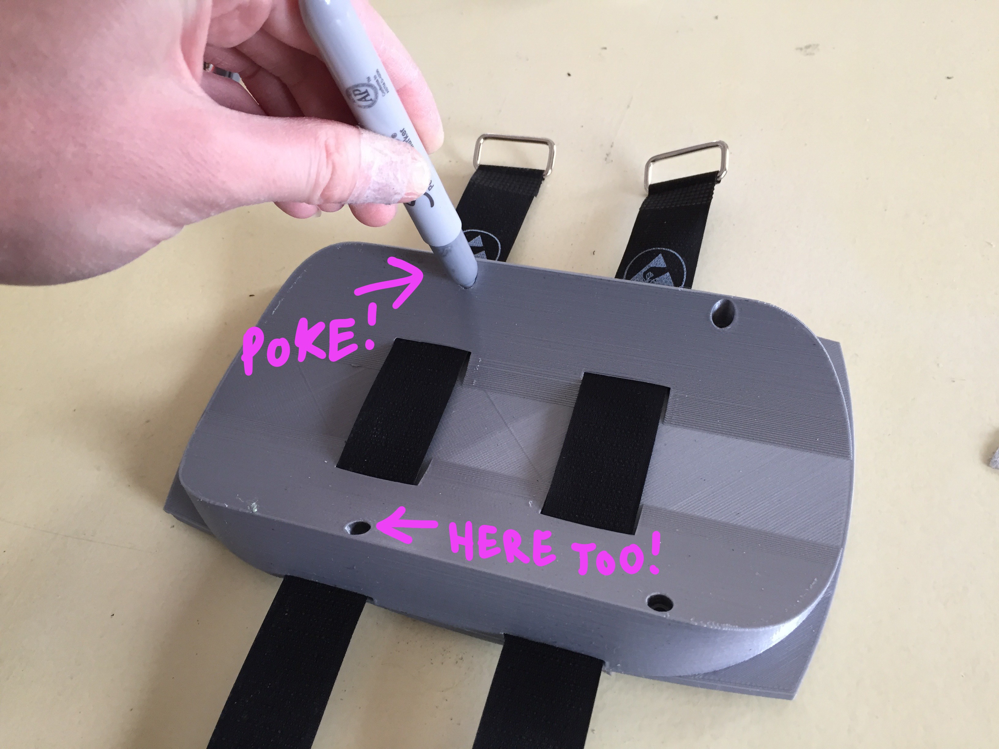
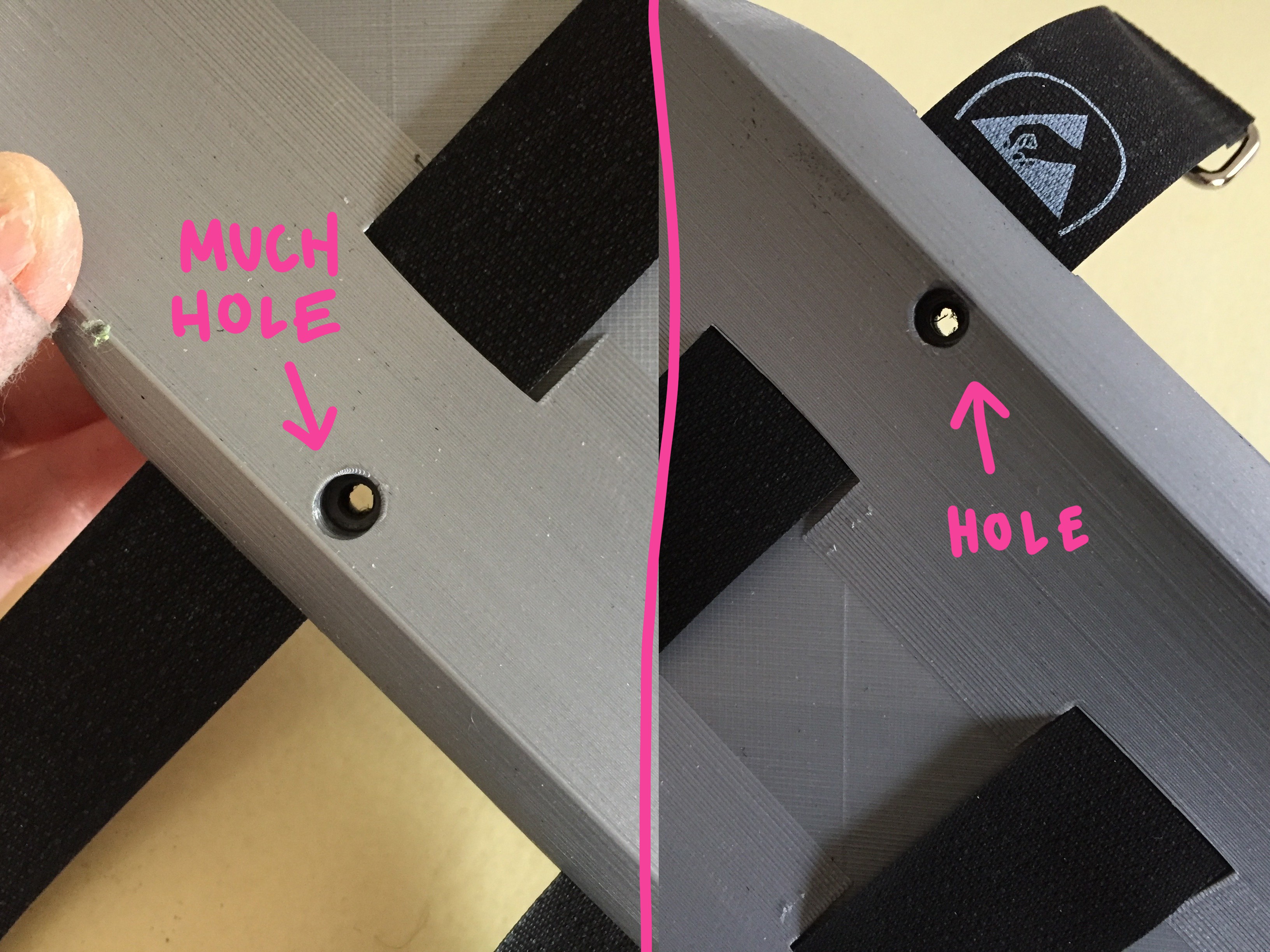
You'll notice one of them has a hole overlapping one of the channels... OOOPS. You will need to pass a piece of hardware through there to seal of the enclosure, so we're going to have to punch some holes in the strap.
Position the straps where they need to be fixed, relative to how they hit the girth of your arm, and then mark where the hole lands with silver sharpie:
Once marked clearly... use a 4mm punch to piece the velcro strap:
Yay! Now the hardware can pass through the strap when you're sealing up the enclosure!
There are four remaining holes at this point =O position the 15mm spacers over these holes and use your 35mm hardware to seal the enclosure, screwing from the "arm capture" plate through the spacers, and into the corresponding holes on the "screen frame" (there should be countersunk nylock nuts ready to receive them!).
CLOSE IT UP
Align the holes of the "arm mount" piece over the remaining 17mm spacers and the remaining holes on the "screen frame":
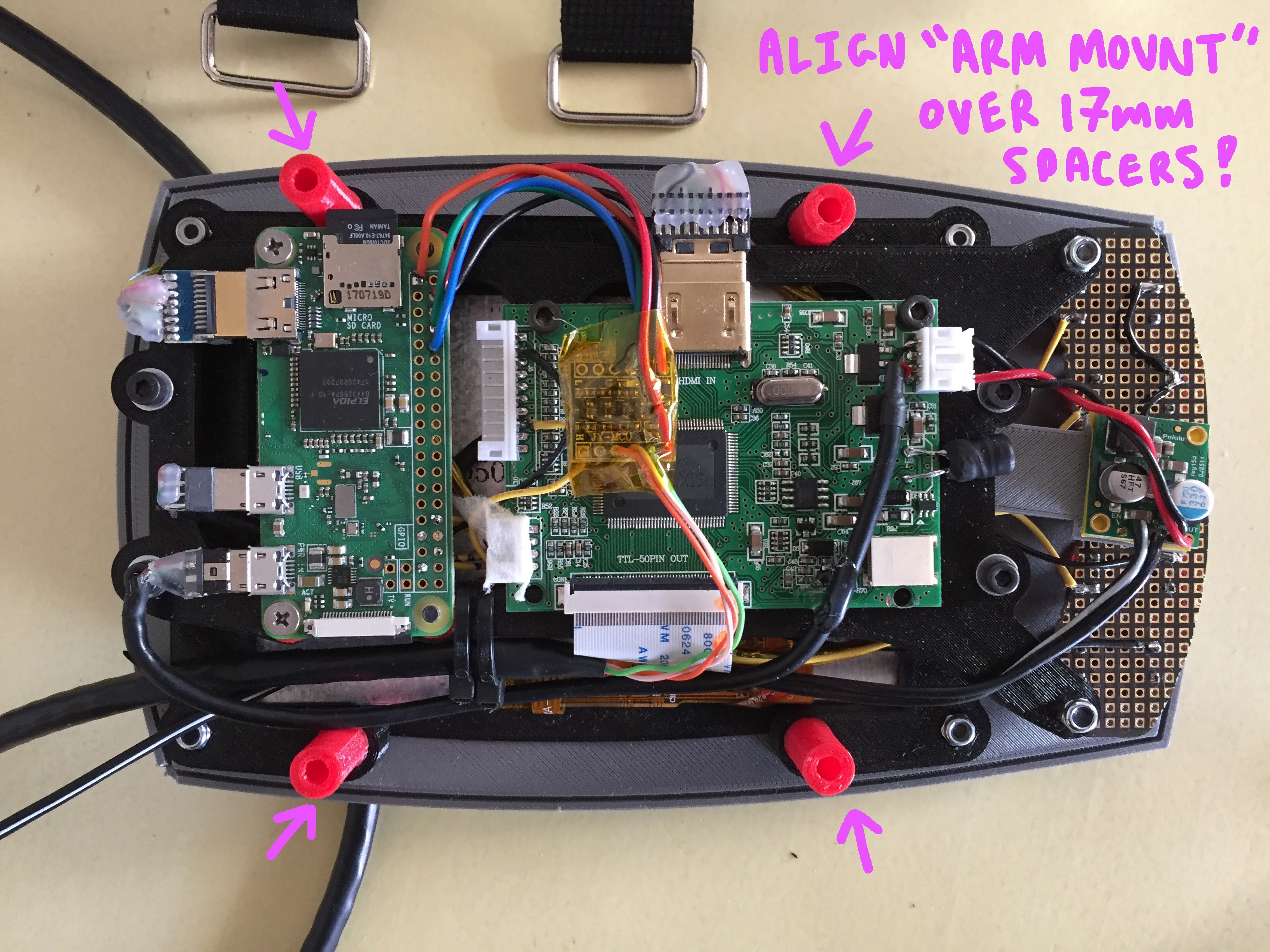
Make sure the cable from the power supply and the CAT5 data line are tucked along the inside of the spacers:
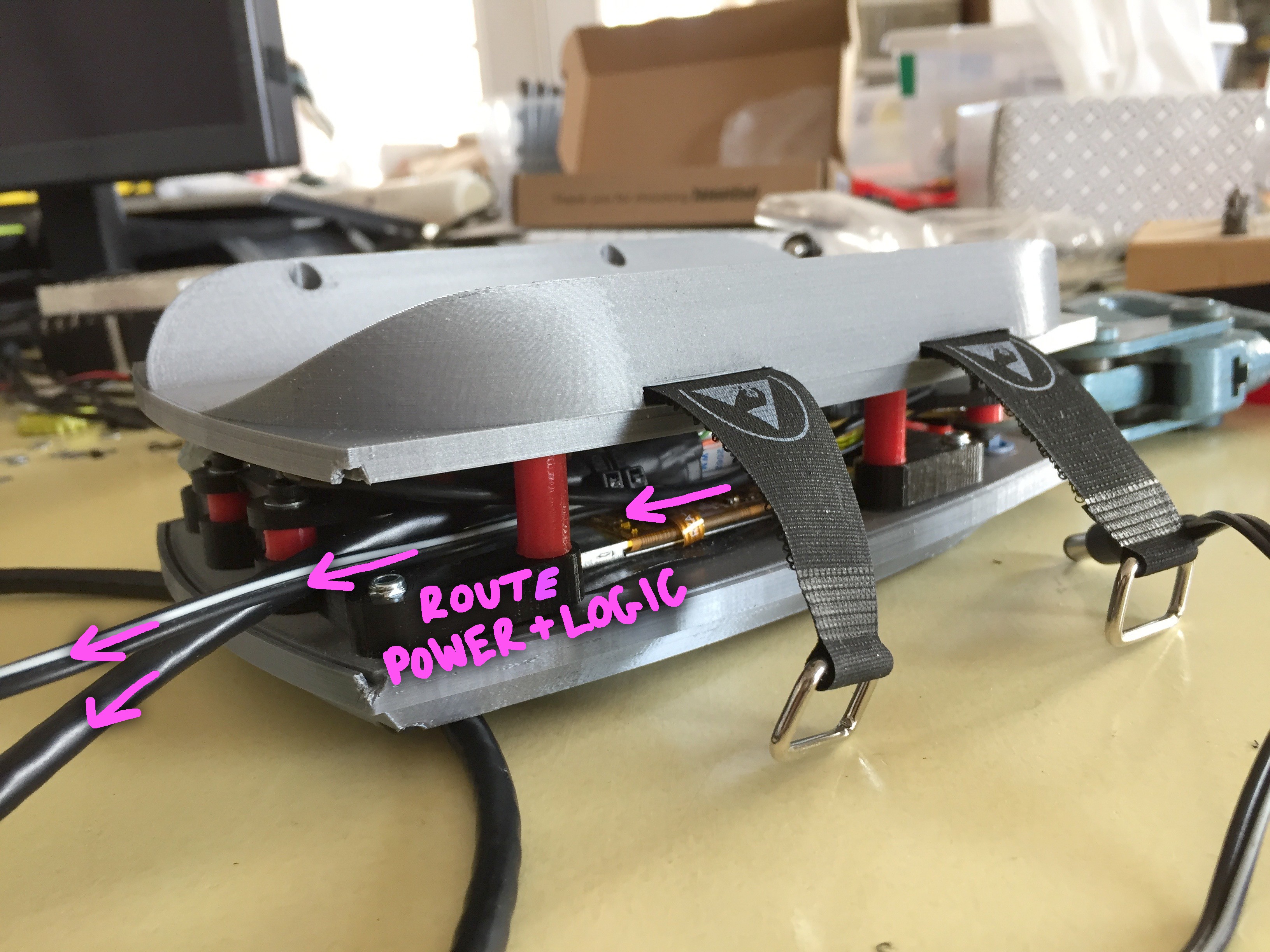
You will use your 40mm to seal the enclosure. Make sure the top assemble and the "arm mount" sandwich the 17mm spacers and that none of your chords or wires are being pinched as your tighten down the screws into the captured nuts in the "screen frame".
CREATE SOME EDGE
Using some sheet plastic, cut small rectangles in the following dimensions:
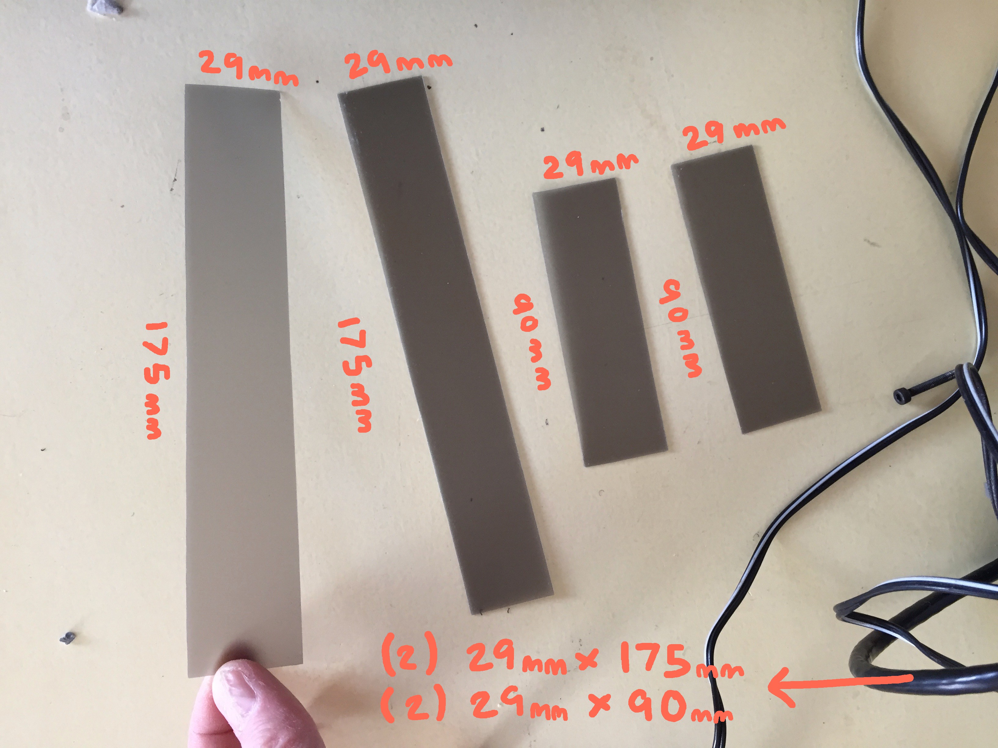
I found some semi-transparent grey sheet that defuses the inside slight from the indicator LEDs on the internal boards quite nicely. Once cut, slide them through the channels along the outside edge of the "face_plate" and the "arm_mount":
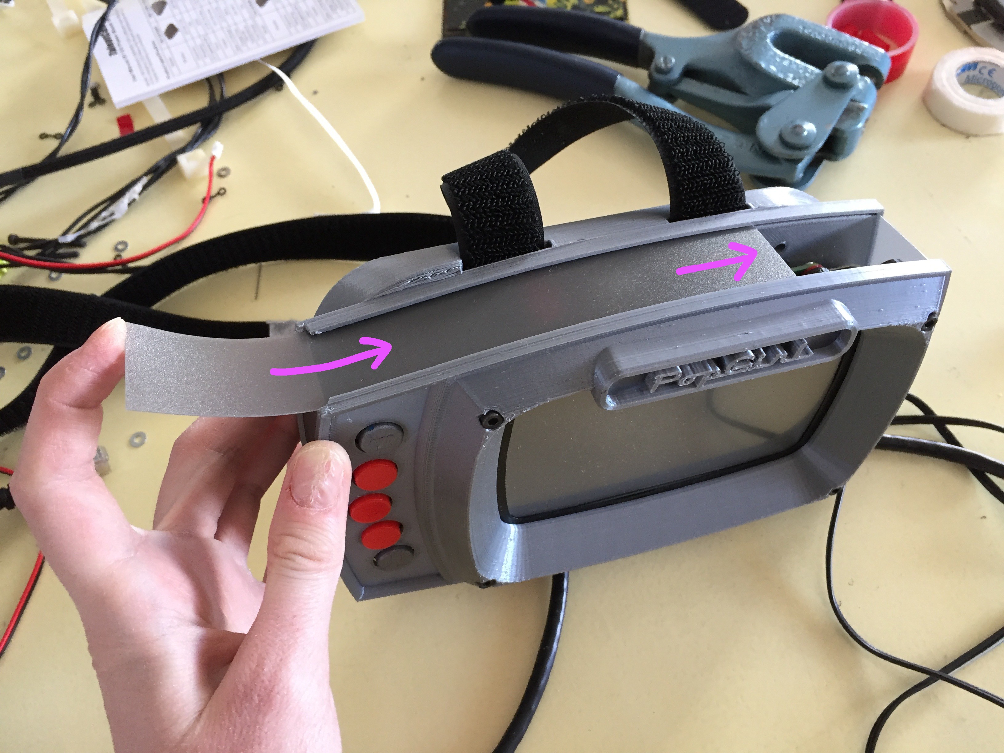
The right side of the enclosure wall should have a hole open for the CAT5 cable to pass through.
Once this finishing touch is added... you are ddddoooooonnnnneee.
The final step is to get the software running on the Pi. So, maybe don't close the thing up just yet. =P
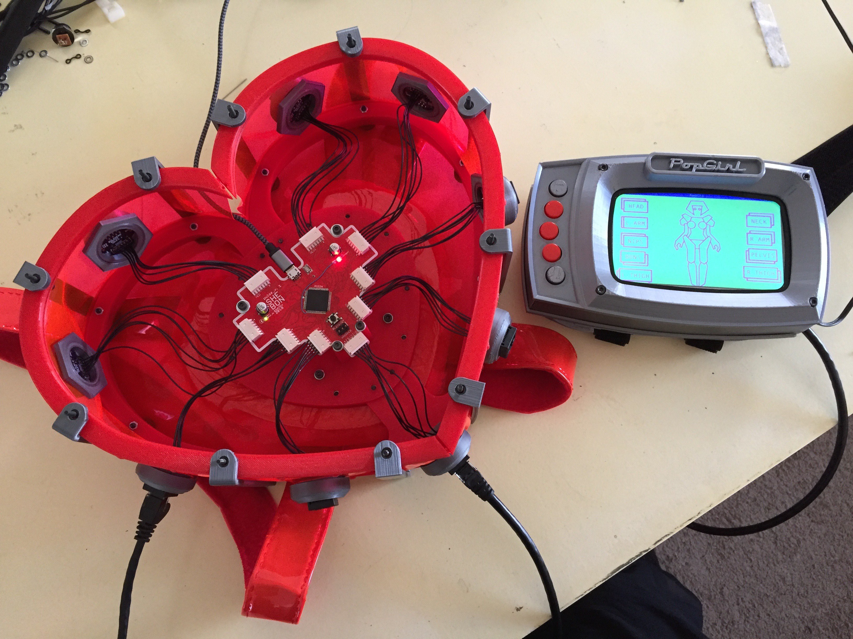
is glorious!
The software instructions will come shortly! Until then- enjoy my wiggly concept sketch of the UI layout!

Discussions
Become a Hackaday.io Member
Create an account to leave a comment. Already have an account? Log In.