 maehem
The pessimist says that the glass is half empty.
The optimist says that the glass is half full.
The engineer says that the glass is twice the size it needs to be.
Design System
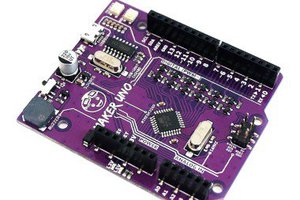
When I started this project I wanted to make something that was off-the-shlef and that I would find useful to my own creations. Although I am a fan of Arduino, I've never used an actual Arduino board in any of my designs and up until recently had never owned one. I've always made my own custom Arduino compatible boards for the specific task at hand. However, my significant-other owns approximately four or five Arduino Uno boards and I watch her go straight to the Uno with a breadboard, components and wires to get an idea up and running within an hour of so. Because I also love to solder, I also haven't used a breadboard in years. I will generally solder up what I need if I am tinkering, which I also don't do much of. Years of being a design engineer has conditioned me to start with CAD and end with a pack of OSH Park boards at my door step. If that goes horribly wrong, Rev.B is only another 10 day wait. So I wanted a "system" that was compact and modular, had alot of the common features I usually use and was something that I could make a dozen more of quickly without it looking like a mess of custom wires. Whenever I look at the Arduino Uno, I always say to myself, "That board is twice as big as it needs to be. Look at all that empty space." When I started Solstice, I wanted an Arduino that I felt I would actually want to use as a starting point for commercial quality designs.
So far I've created the base board called StarFire which features 16 WS2812B (NeoPixel compatible) LEDs along the edge. The Rev.0 board uses 5mmx5mm LEDs giving the board a dimension of 60x52mm, but the next revision will use 3mmx3mm LEDs and shave 4mm off the board width (for a size of 60x48mm). The "Albedo" variant of the board will not have the LEDs at all and will bring the outline of the board down to 60x42mm.
I once destroyed one of the few Arduino boards I've ever owned by assuming that the holes provided on the board could be easily used as mounting points. That burning smell means failure. Not only do Arduino's mounting points have minimal clearance for screw heads and stand-offs (there are traces running close to the holes), they don't really fit a regular grid pattern either. Solstice addresses this by giving the user a solid 54 x 36mm hole grid pattern and accepts M3 screws. I oversized the plating clearance around the grounded holes to ensure that standard socket head screws will make good contact with ground and won't short out nearby traces. And except for the 0.1" perf board accommodation, all dimensions are in metric!
Pinout
The Solstice system pinout is mostly similar to Arduino with a few differences. All the digital pins are on a single edge. The digital pins also include the +5V rail and grounds so that prototypers could potentially plug the Solstice board into a bread-board while having 80% of features available without additional wires. The opposing edge features the analog pin section, which also groups the A-Ref pin in there. That edge also has a group of pins featuring raw V-in, regulated 5V, regulated 3.3V, Reset and two ground pins. The genuine Arduino has one set of header pins that are offset by 0.05" and prevents the use of standard perf board in many situations. I was careful to make sure that the 0.1" header rows stayed on a 0.1" grid across all header locations (including the ISP header) so that hobbyists can choose to use standard perf board with most of their shield prototyping.
Shields (HaLo and Umbra)
The Solstice shields are called a HaLo (Hardware Locus) and measure 60mmx42mm in most cases. We will be open sourcing the HaLo outlines as EagleCAD library parts in...
Read more »
 DIY GUY Chris
 Albert van Dalen
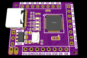
 Kirroslink
At least publish an example sketch? :)