 deʃhipu
So I started to work on the new PCB, using a QFN48 foorprint for the SAMD51G. Of course the footprint I made earlier for the IS31FL3733 chip was inexplicably broken — as soon as I started editing the pin descriptions it started doing really weird stuff. So I re-did it, together with a proper schematic image and all that. Then I started with the PCB I re-did recently for the #D1 Mini Tote, only replaced the PCA9685 with the SAMD51G:
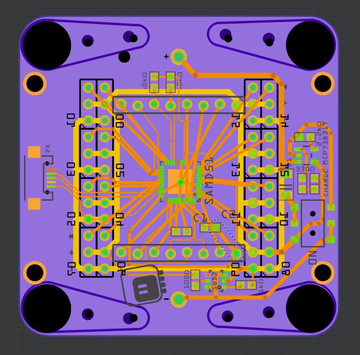
Yes, it's a mess for now. Ideally, I will use the same headers as for the D1 Mini, so that I will be able to use all the D1 Mini shields with this robot — including the #Accelerometer Shield for D1 Mini I made recently (that's one reason why I removed the accelerometer from the PCB, actually). However, I still don't know which combination of pins will have the correct set of timers for making all those PWM outputs. But I'm confident that such a set of pins exists, because of an experiment I made with an ItsyBitsy M4:
import board
import pulseio

pins = [
 'D7',
 'A1',
 'D0',
 'D1',
 'D2',
 'D4',
 'D5',
 'D9',
 'SCL',
 'D10',
 'D11',
 'D12',
 'D13',
]

pwms = []
for name in pins:
    pin = getattr(board, name)
    print(name)
    pwms.append(pulseio.PWMOut(pin, frequency=50))
So yeah, I can have at least 13 PWM outputs — I'm sure I can find a set of pins that will work. Whether they will be easy to route is another question, but I have a lot of space and as many vias, as I need. Also note, that on the current PCB I actually have 16 servo sockets, not 12 — ultimately there will be 4 fewer.
I will probably also add a flash chip and that speaker with an amp — this way I can put all the turret voices from Portal on it.
Discussions
Become a Hackaday.io Member
Create an account to leave a comment. Already have an account? Log In.