 deʃhipu
I still have no strength to sit down and program a proper gait, but I keep thinking about the mechanical design and having ideas. One thing I'm going to need is some kind of an expansion socket on the front part of the robot, so that I can connect different kinds of sensors, displays, faces, etc. I could simply just have a pin header with all the unused pins broken out randomly, but that's not very convenient. I could have several headers, to match several of the modules I want to be able to connect, but that gets complex fast. Or I could use some kind of a standard footprint — for example the one for Adafruit Feather, so that I can connect FeatherWings to it. But here is a small problem: the Feather M0 uses a larger SAMD21 chip than I was planning to use — does my chip have enough pins to re-create the pinout?
So I went to Adafruit's website, grabbed the schematic they published, and started working:
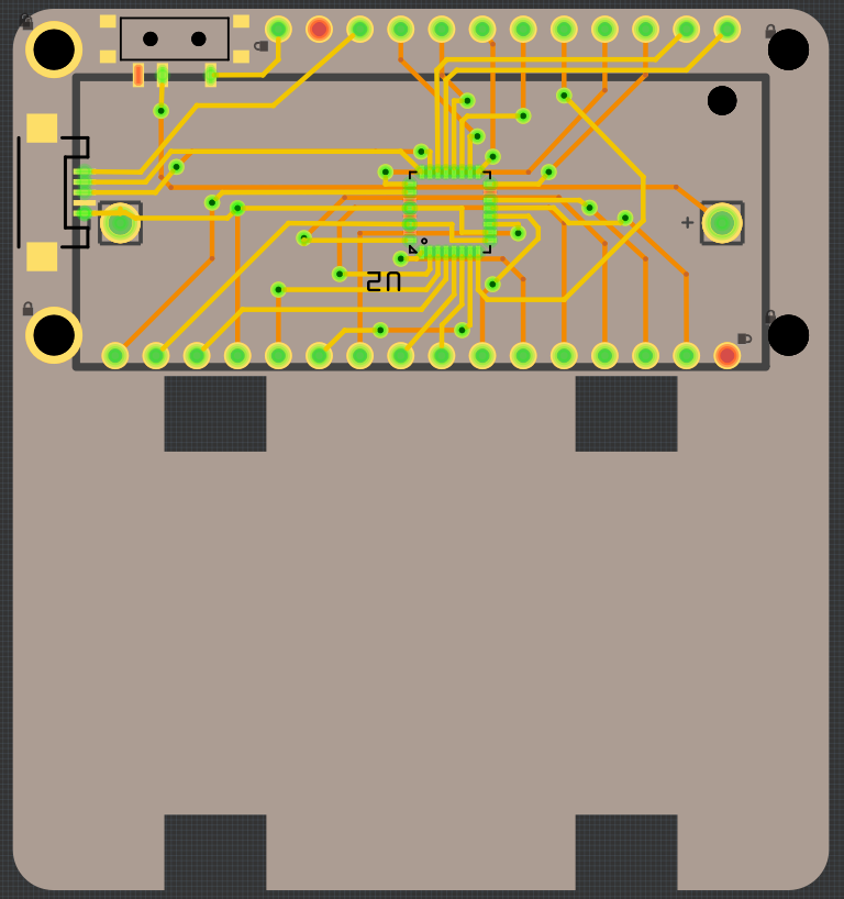
The answer is yes, you can do it, with only 7 pins that are not available on this chip, but easily replaced with other pins. And you still have 3 pins free!
Unfortunately, I need at least 8 additional pins to control the servos, and they have to be timer-capable pins to do PWM. So either I switch to a chip with more pins (and at this point it would probably be SAMD51, because I already have it in my drawer), or I use some of the pins that are unlikely to be used by the FeatherWings that I need — in this case that would be the analog pins. I would leave the A0 (because it also has DAC), and re-reoute A1-A5 to the servos, which together with the 3 extra pins should be enough. I would need to do some experimenting to see if all of those pins are PWM-capable, and probably swap some of them around if they are not — something that requires more effort than I am ready to spend right now.
Second thing I was thinking about is the mechanical design. I think I figured out how to best attach the servos to the main body of the robot, without needing to solder loops of paperclip wire to the PCB. See those four slots in the PCB? You just need small horizontal bars that go inside them, with holes for the servo screws. They will push against the outer edge of the slots, and the servos will push against each other, and that should give you a pretty solid attachment.
And the next thing — I originally designed this robot to be just a single piece of PCB, that you just break to get all the parts for the legs and body. This way you don't need access to a laser cutter or a 3D printer. But after my experiences with #PewPew M4 I discovered that it is very easy to order your laser-cut parts together with the PCB, and they are so much cheaper than the PCB is! They also are thicker and look better, so there is really no point in using PCB for construction anymore. That brings me to redesigning the legs and the body to be laser-cut, and the PCB to be as small as possible and attached on top.
Discussions
Become a Hackaday.io Member
Create an account to leave a comment. Already have an account? Log In.