It has been a long time coming, but the custom SOL device is finally working.
After assembling the SOL_R1 design, and charging the battery, I measured the output of the 3.3V MIC5205 voltage regulator with a multimeter as about 1.4V. After looking further at the datasheet for the MIC5205, I noticed that it is not compatible with a ceramic output capacitor. I did not have an oscilloscope on hand to examine the output waveform, but it was likely oscillating such that the averaged measurement seen on the multimeter was about 1.4V.
A few solutions seemed reasonable. One option was to switch over to the MIC5245 voltage regulator, which is pin compatible with the MIC5205 and is stable with a ceramic output capacitor. Or I could change the output capacitor for the MIC5205 to the recommended 2.2uF tantalum capacitor. I ordered both options.
Once the MIC5245 device arrived, I built SOL with it. Unfortunately, the output voltage was still bad, hovering around 0.4V. At this point I realized what should have been obvious earlier -- these voltage regulators can only supply up to 150mA, but the ESP32 datasheet recommends a power supply of at least 500mA. While the first version still would have been unstable with a ceramic capacitor as set up, the second attempt likely would have been stable, but was unable to supply enough power.
Thankfully, there is a pin-compatible 500mA voltage regulator (RT9080) which I was able to switch to without making new PCBs. After installing this part, the output voltage was a stable 3.3V!
The next step was to program the device with the SOL firmware. I used the 3.3V FTDI Basic USB-to-serial converter from SparkFun. I connected GND, TXO on the FTDI basic to RXD on SOL, and RXI on the FTDI basic to TXD on SOL. When I attempted to program the device, it did not respond. I then realized that the ESP32 needs to be put into the ROM serial bootloader mode. This website explains the process. GPIO 0 and GPIO 2 must be held low. SOL was designed to use GPIO 0 as a touchpad input, so this pin was easily accessible. For GPIO 2, I had to carefully touch a jumper wire connected to ground to the correct pad on the ESP32 module. Once I did this, the device was programmed!
I confirmed the device was able to measure power from the solar panel, was able to connect to WiFi, and was able to upload data to Google Sheets.
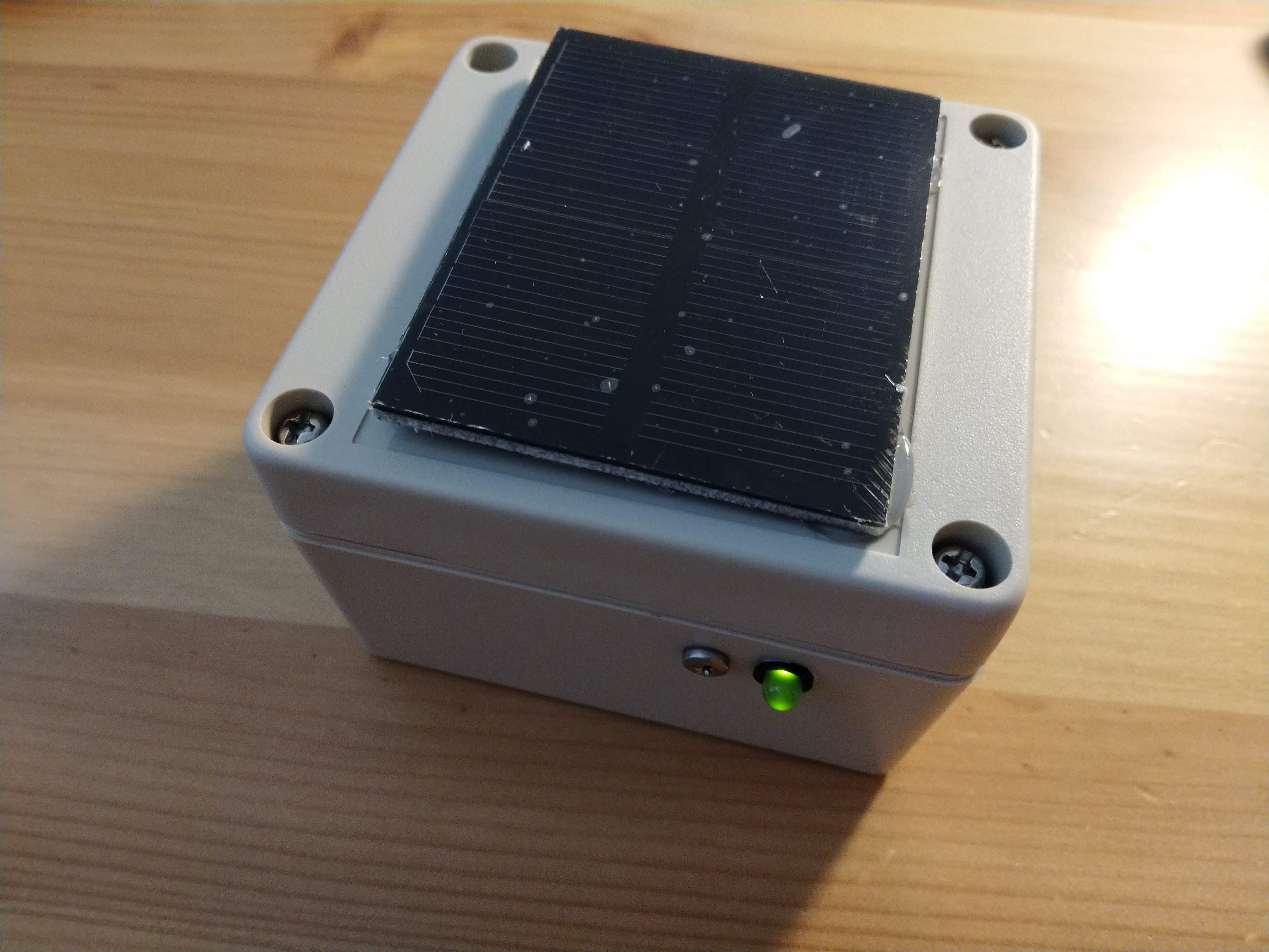
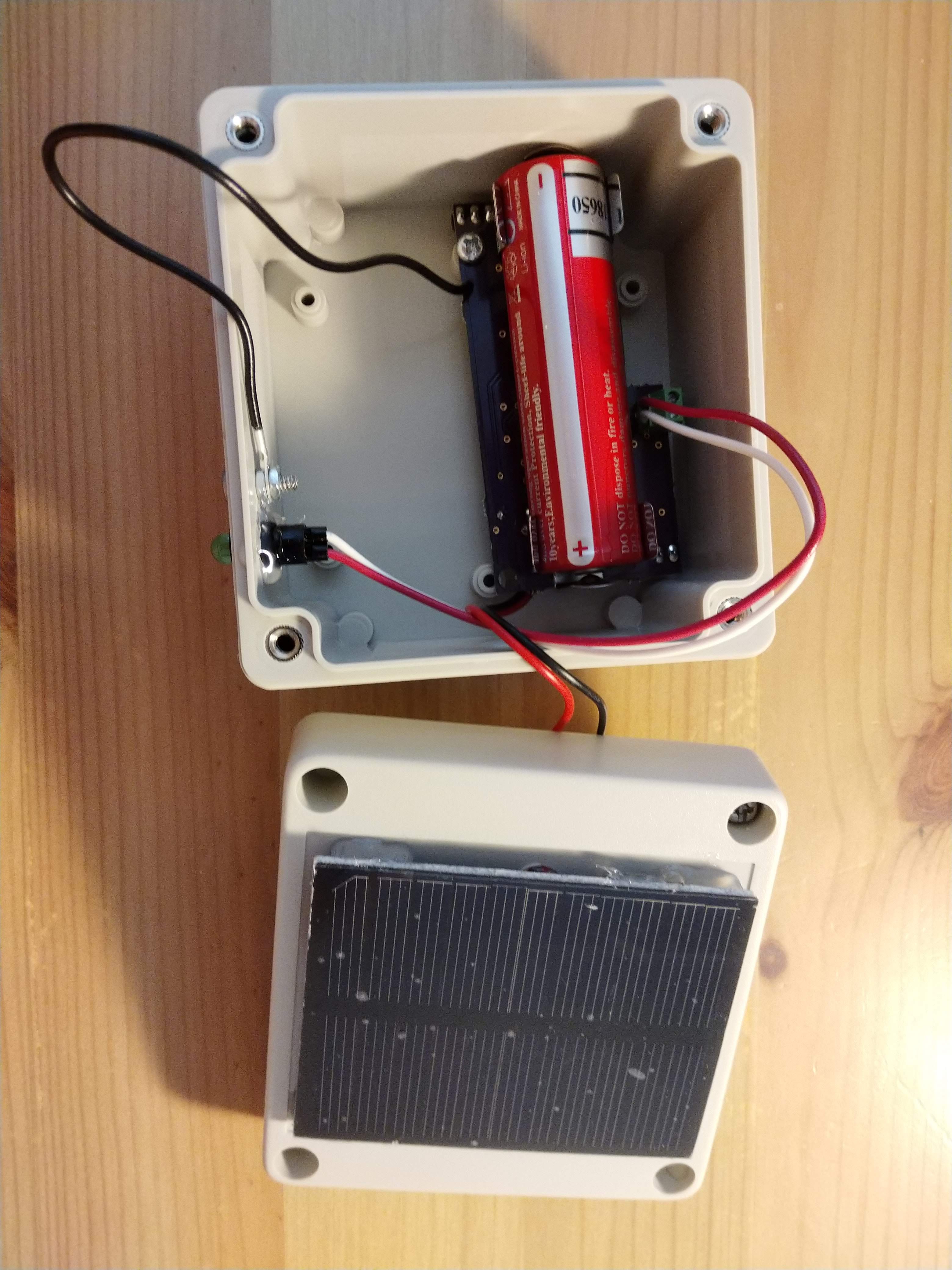
Next, I worked to assemble SOL into its case. I used an off-the-shelf IP65 waterproof case (RP1065.) I added a hole on top for the solar panel connection, and two holes on the side. One hole was for the a panel mount LED, and the other is for a bolt with gasket used as a capacitive touch input. Ideally, this setup will be waterproof, but quick testing showed some leaks. Likely this is from the panel mount LED, which does not have a gasket and is not very accessible for adding waterproofing. Making this setup waterproof will be a next step, so that SOL can be left outside.
Discussions
Become a Hackaday.io Member
Create an account to leave a comment. Already have an account? Log In.