Version 3 Goals
Version 3 had a few simple goals. First and most obvious was to fix design mistakes in version 2:
- The trace from the output of the temperature sensor to the ESP32 ADC was accidentally overlapped by a ground trace, causing version 2 to not be able to measure temperature.
- I forgot the load capacitors on the RTC oscillator, so the RTC did not keep time.
Second, version 3 was designed to be easily programmable. All the necessary pins were brought to a ZIF (zero insertion force) connector, and an adapter board for a FTDI Basic 3.3V was made, so that I could use the two onboard buttons to toggle EN pin (to reset) and IO0 pin (to enter bootloader mode), without having to manually touch jumper wires to ground.
Assembly
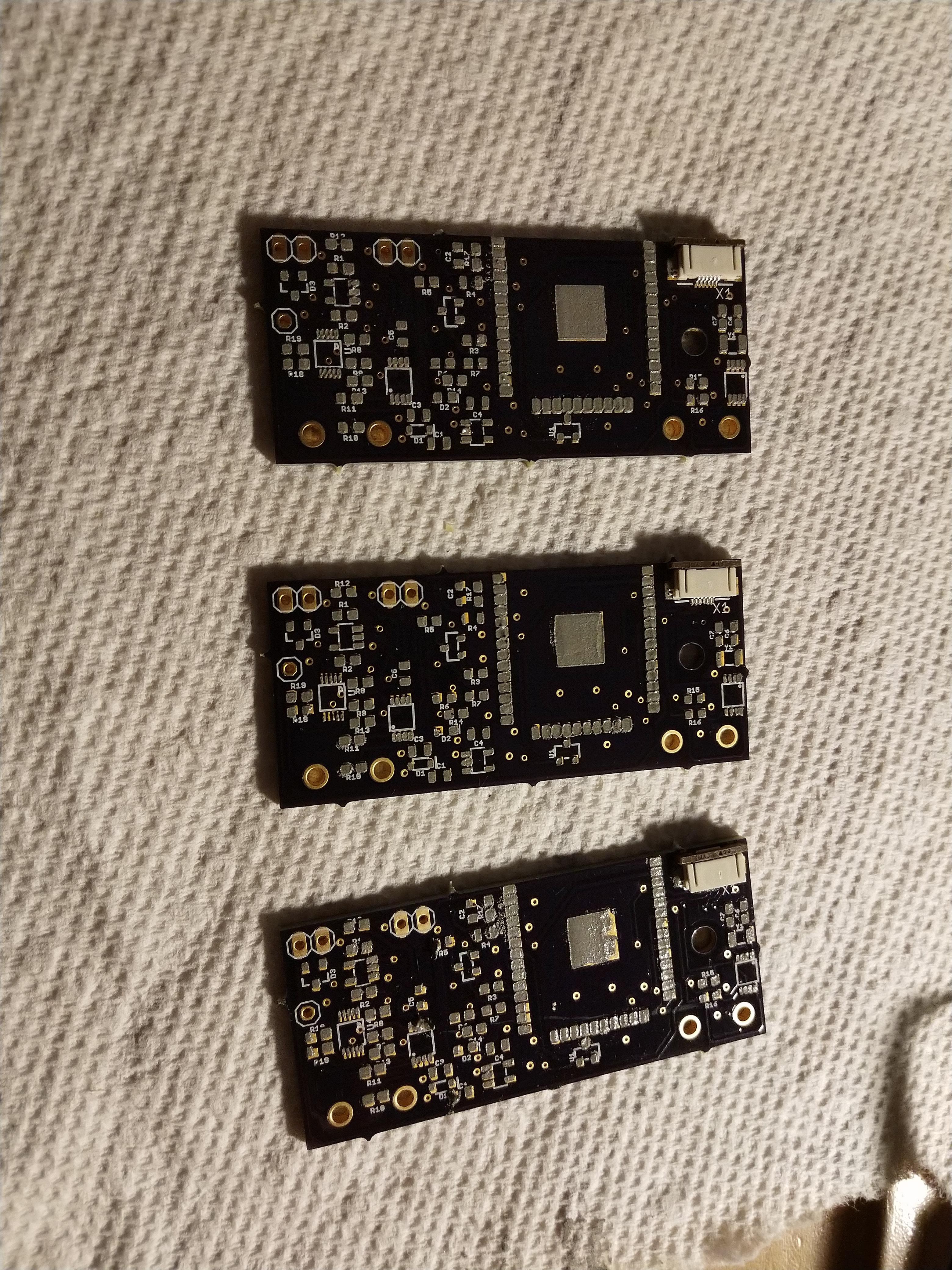
On previous versions, I assembled by laying down small bits of solder paste on each pad using the syringe it comes in. However, this process is very slow, and often results in too much solder paste on fine pitch packages. For version 3, the ZIF connector is a 0.5mm pitch package, so I bought a stencil from OSH Stencils, and used that to apply the solder paste. This gives a more even amount of solder paste on each pad, and speeds up the assembly process. The three version 3 boards I assembled are shown below with solder paste applied and the ZIF connector placed.
As previously mentioned, version 2 was a bit of a pain to program, requiring me to manually touch jumpers on the EN and IO0 pins to ground at certain times. I did this by connecting through a breadboard. It worked, but it wasn't good, and I had to be very carefully not to accidentally short something.
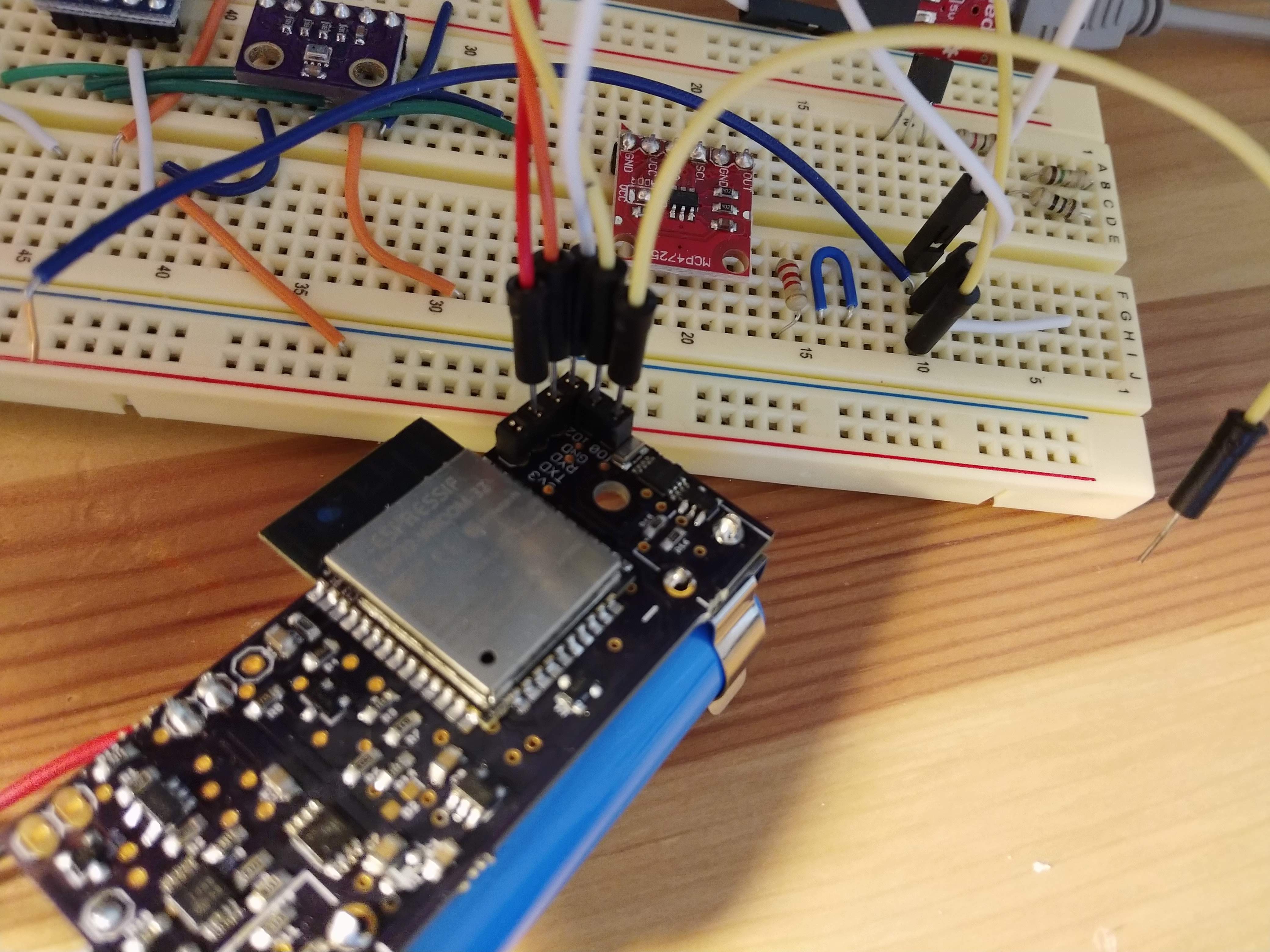
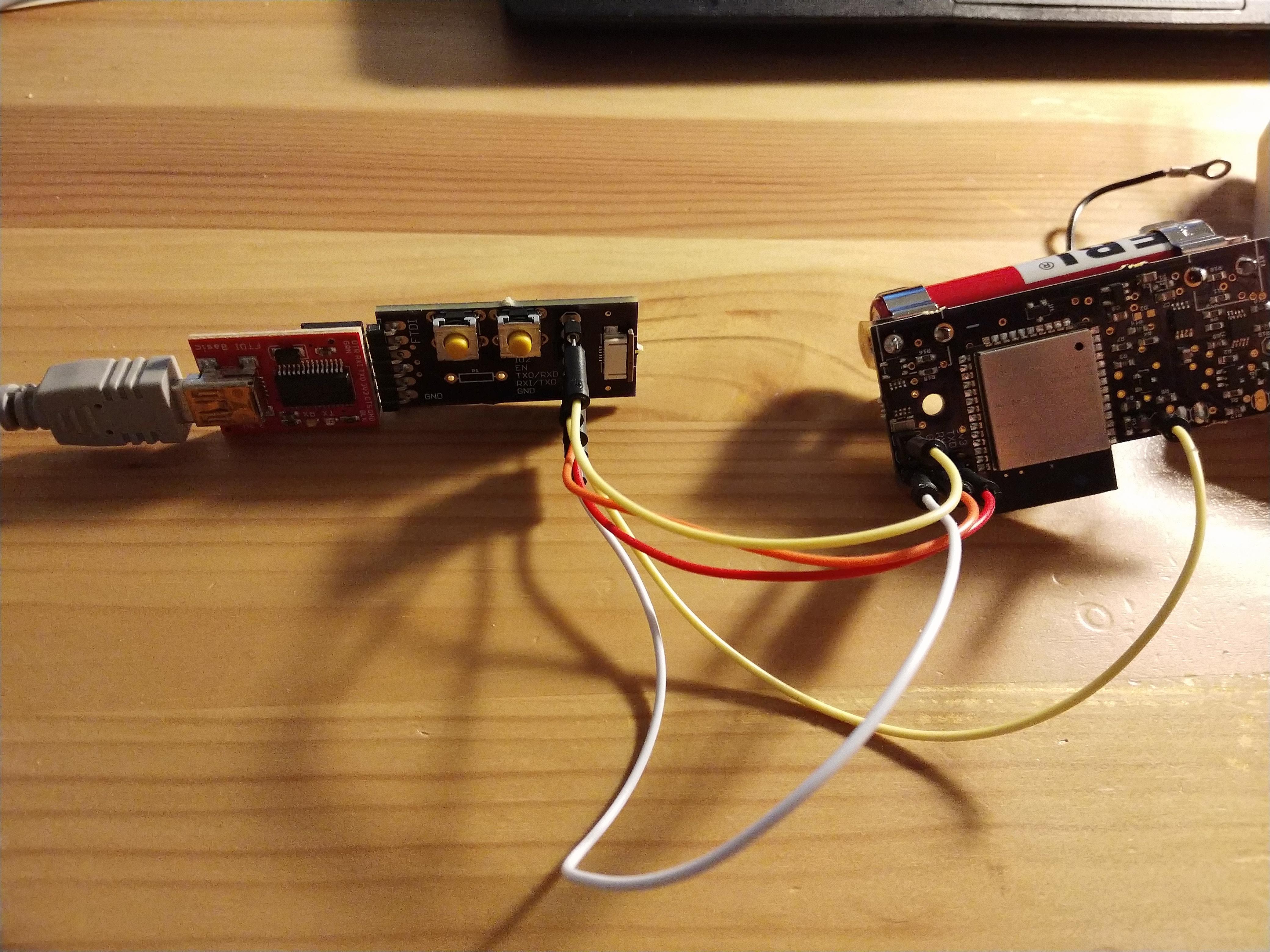
To fix this, I built an adapter board for the FTDI basic, which has the corresponding ZIF connector for version 3 programming, as well as female header pins for programming version 2. Below, the adapter board is shown connected to version 2. The two buttons on the adapter board are for reset and bootloader entering.
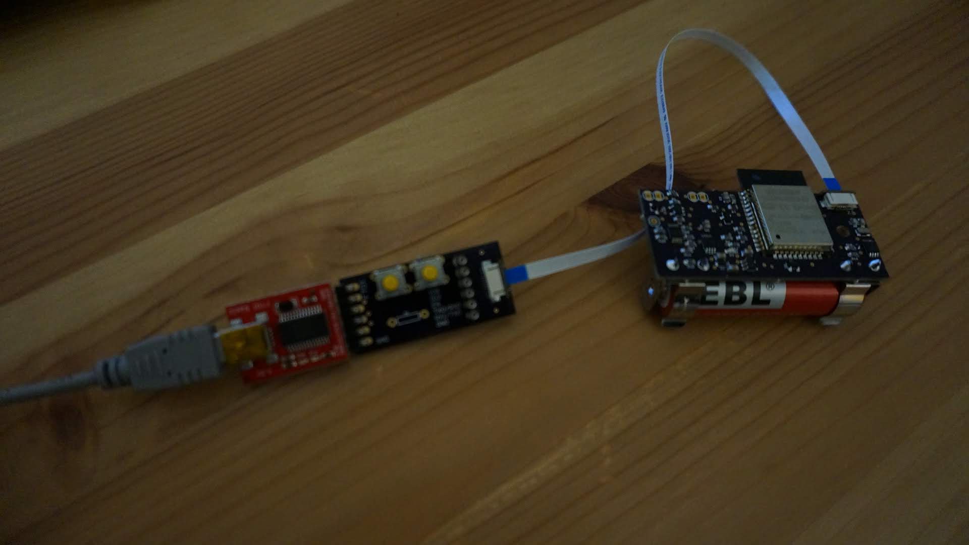
When used with version 3, the ZIF connector and FFC (flat flexible cable) allow me to program very easily, by just clicking the buttons before (holding the IO0 button while toggling EN to enter bootloader) and after (toggling EN to reset after programming).
Server Setup
Ryan has done some great work setting up a server at solsensor.com (all source is here). This allows us to step away from the simple IFTTT/Google Sheets setup used previously. While that was useful as a proof of concept, it obviously wasn't a long-term solution. It limited the amount of data that could be uploaded at each API call, and had restrictive rate limiting. Our server does not yet have a front end to show the data, but works well as a back-end.
Firmware Re-write
The new server side built by Ryan led me to re-architect the SOL firmware. The old firmware was admittedly hacked together to get it working, but I was waiting to redo it until the server side API was designed. This firmware will be put in the github soon. There are some major changes:
- SOL V3 does not have an EEPROM chip, so all datapoints between uploads are stored on the ESP32. The RTC memory is used to cache datapoints in RAM, and then data is stored permanently in a SQLite database in the ESP32 flash memory.
- The connections to the server are all new. HTTPS is used to upload data in batches to the server. This showed some limitations in the ESP32 hardware.
- The API includes an endpoint to upload a single datapoint, or an array of datapoints. At first, I uploaded the data one-at-a-time with the single datapoint endpoint, but this was VERY slow. It took about 3-4 seconds per datapoint, which is pretty unacceptable, given the low power needs of SOL. It's not 100% clear why, but my guess is this is due to the encryption needed for HTTPS. When I changed to uploading data as arrays, the time per data chunk was still 3-4 seconds, even though 100 datapoints or more are uploaded at a time. The firmware allows me to define the chunk size here, and uploads all new data as a number of chunks, vastly improving throughput.
- Data needed between sleep cycles are stored in RTC memory where possible, speeding up access to that data, and ensuring the device is in low power modes as much as possible.
- The new server API uses access tokens provided by the server, so no keys need to be programmed into the firmware. The same firmware can be used by anyone, and they can connect it to their WiFi, and provide their SOL credentials so that the device can get the proper tokens. The SOL credentials are not stored long-term, only the access tokens are, and the device access tokens only allow the device to add data, improving security.
Testing
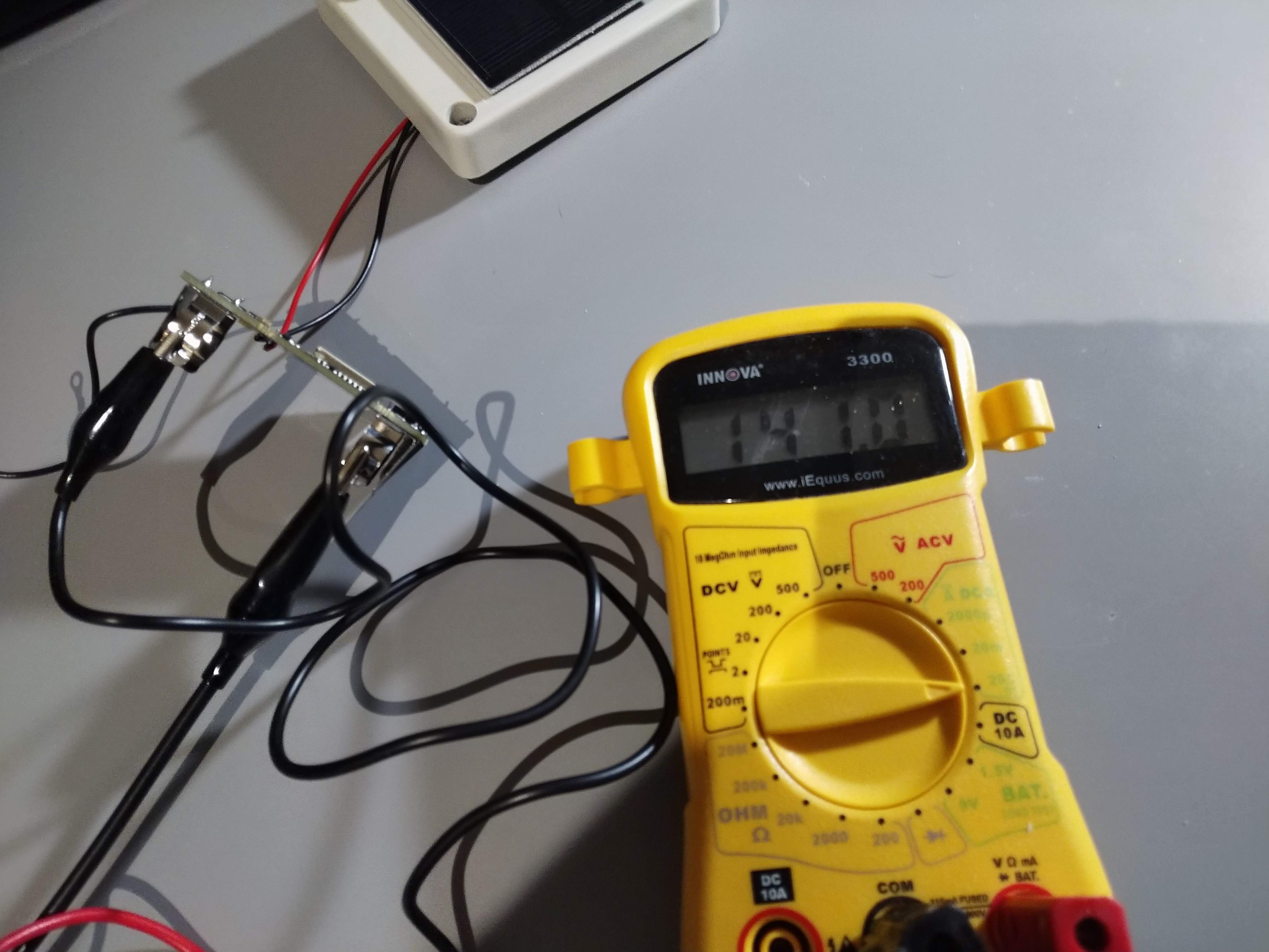
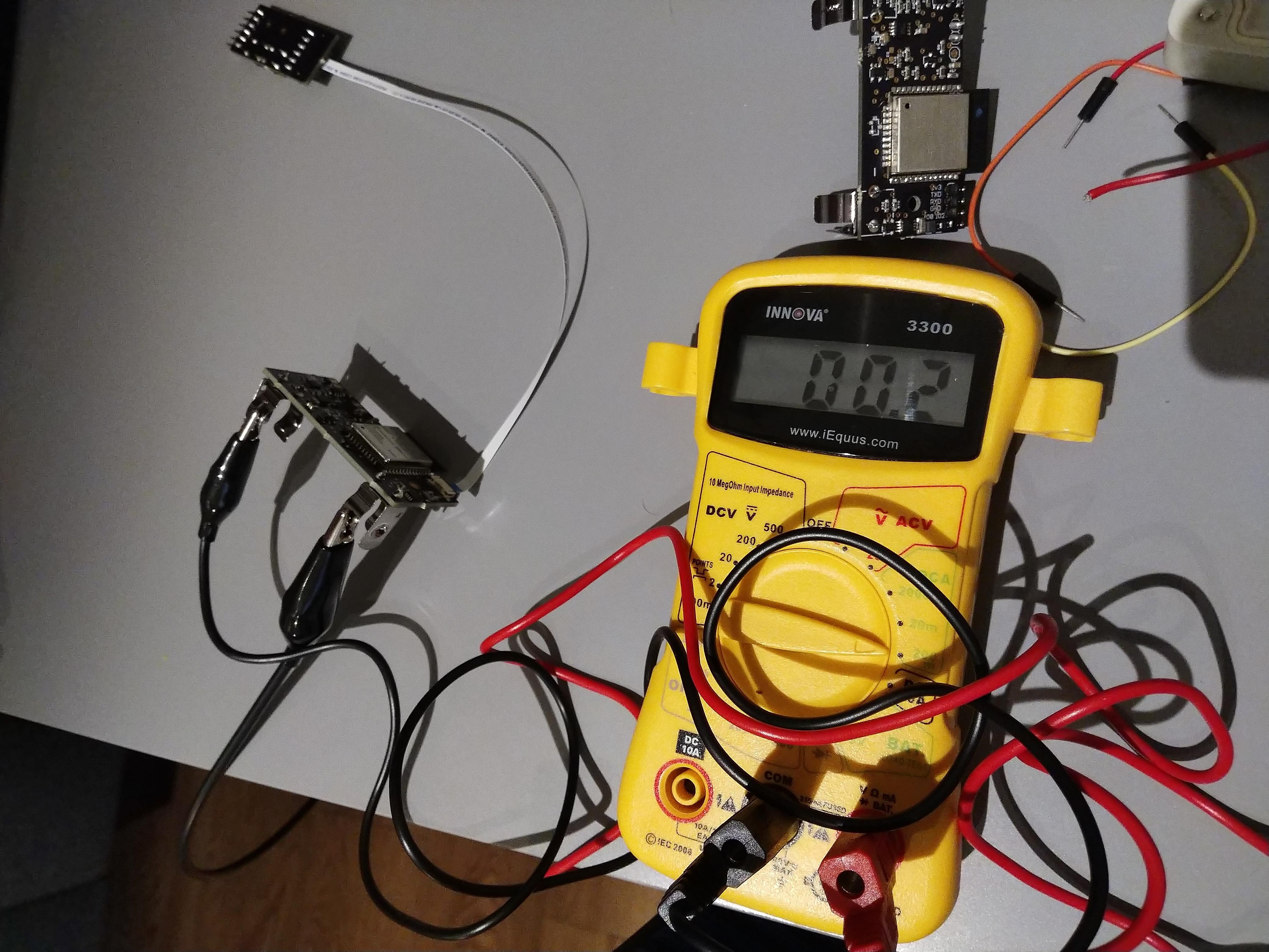
Some of the first testing I performed was on power consumption, to ensure the device is achieving the proper power consumption in low power mode. SOL was powered with a power supply through an ammeter, and current consumption was monitored in low power mode and when the device was awake with WiFi on. With WiFi on, current consumption was about 140mA at 4.2V. In low power mode, current consumption was about 0.2mA at 4.2V. The ammeter used was built into a cheap multimeter, so accuracy at that level is suspect, but this level is about what was expected, and is low enough.
Another issue from the previous firmware was how long it took to take a measurement of the peak power, voltage, and current from the solar panel. The ADC used has a PGA (programmable gain amplifier) with 5 useful gain settings, and 2 channels are used in this step, one for voltage, one for current. The ADC is controlled through I2C, which even at 400kHz isn't all that fast. Worse, the ADC has max sample rate of 3300 SPS. As it was, the concept of measurement was to sweep the DAC output as input to the MOSFET, and sweep through the PGA gains. Through it all, the voltage, power, and current were measured, and maximums reported. For each measurement, I also found the ADC results questionable unless I measured twice and threw away the first measurement. Overall, with 256 DAC levels, 2 sets of 5 PGA gains, and 4 measurements needed per DAC/gain set at 0.303ms per measurement, a full sweep takes a minimum of about 7.7 seconds, ignoring delays in I2C. In reality, I measured this to take about 9.5 seconds. For low power consumption, SOL must be in low power mode for the vast majority of time, so measuring for nearly 10 seconds is unacceptable.
Because of this, I created a fast algorithm for power/voltage/current measurement from the solar panel. In testing, this took about 0.27 seconds (about 35X faster), and consistently provided the same measurements as the full sweep method. All details are in the firmware. This allows SOL to wake up, take a fast measurement, and return to sleep quickly.
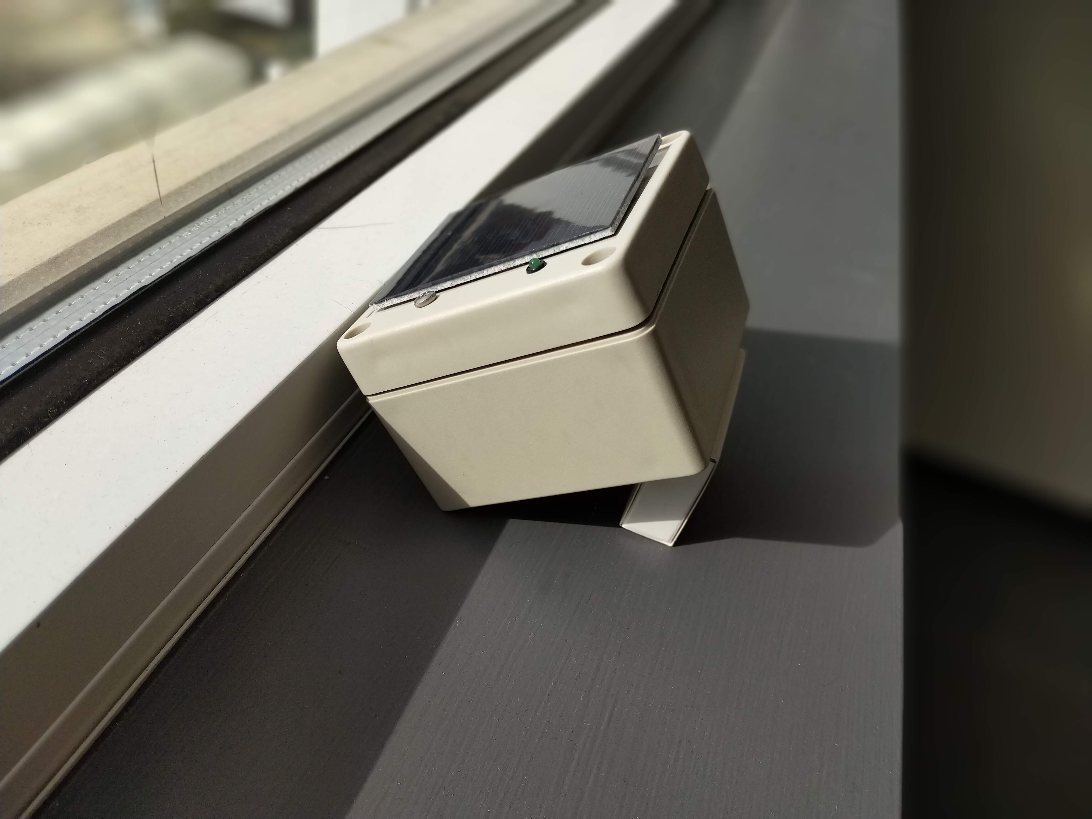
Once the firmware was written, I set up SOL in my office window for a workday. I propped it up to look out the window and receive power better. My window does not receive direct sunlight until later in the day (faces mostly west), and this day was cloudy until the early afternoon. There are also nearby buildings occluding the view.
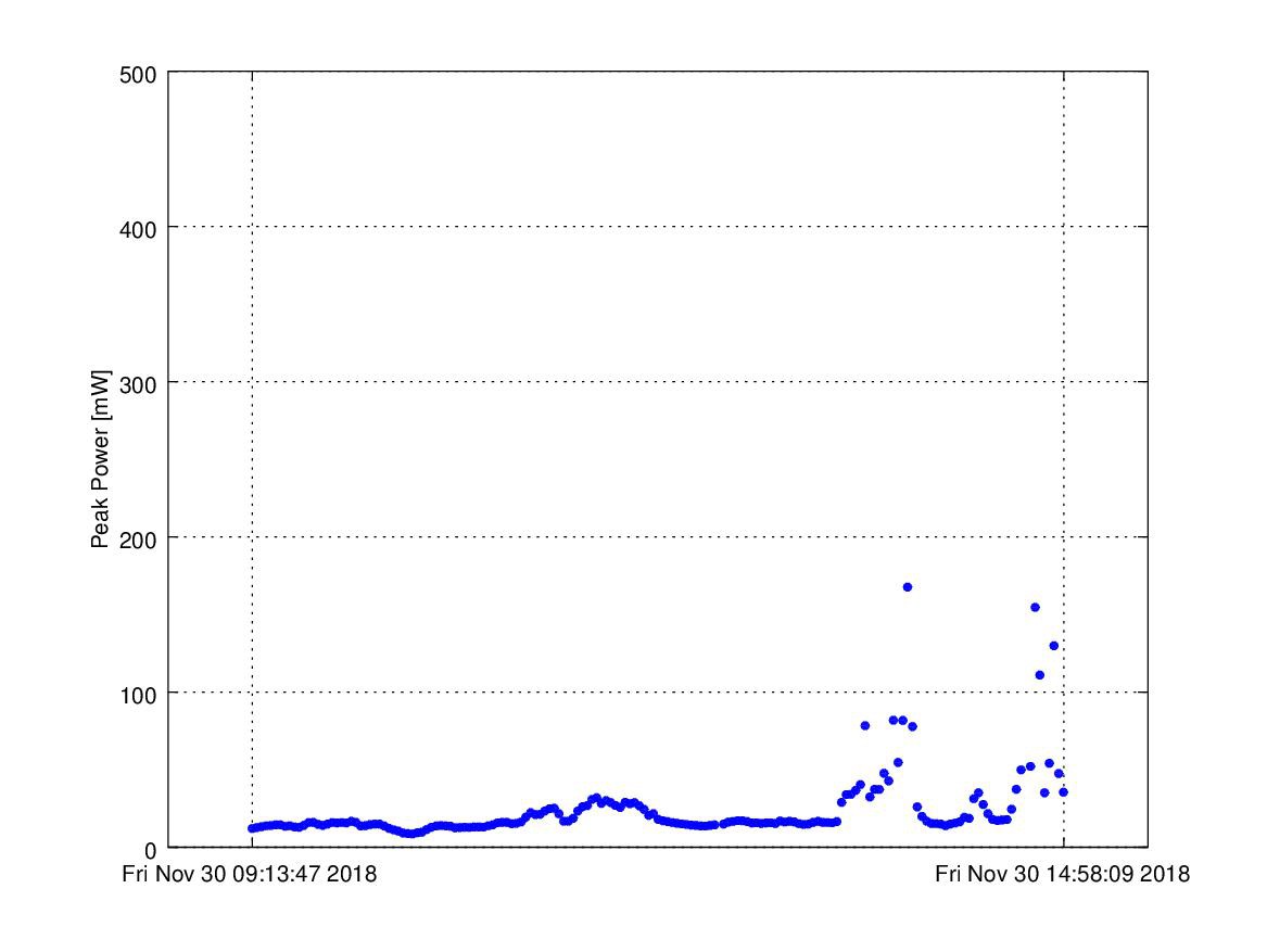
The data shown below is directly from the solsensor website, showing how the whole system was working. The data from the morning to midday is very nicely consistent, with some increases and decreases in power measured. Later in the day, the sun occasionally peaked through the clouds, resulting in significantly higher measurements. The time interval was 2 minutes here.
The temperature measurements implied the power increase shown here is real. While the office was warmer than shown here, it seems next to the window was cool. The device cools off at the start after being placed by the window (it was likely warmer at start due to WiFi being on for provisioning). Regardless, the temperature clearly increases later in the day, indicating the incident power from the sun increased. There are a couple of flat sections that look like there was a possible measurement issue.
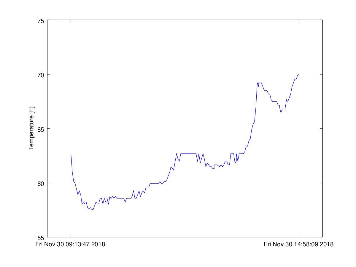
The data shown here ends at about 3pm due to some bug in the firmware, which appears to be tied to the batch upload of data. I will be looking into that soon.
Summary and Next Steps
This progress is very encouraging, and is basically a "hello world" for the project. All basic needs are fulfilled. SOL has firmware that achieves the needed low power, seems to be measuring the solar power data correctly, and is flexible enough to allow the user to provision the device to their own WiFi network and SOL account without reprogramming needed. The server side handles account creation, token generation and authentication, and storage of data.
Next steps include further firmware debugging, documentation, testing to ensure SOL can charge its battery from the solar panel, and website front-end for data viewing and analysis.
Discussions
Become a Hackaday.io Member
Create an account to leave a comment. Already have an account? Log In.