 Brian Barrett
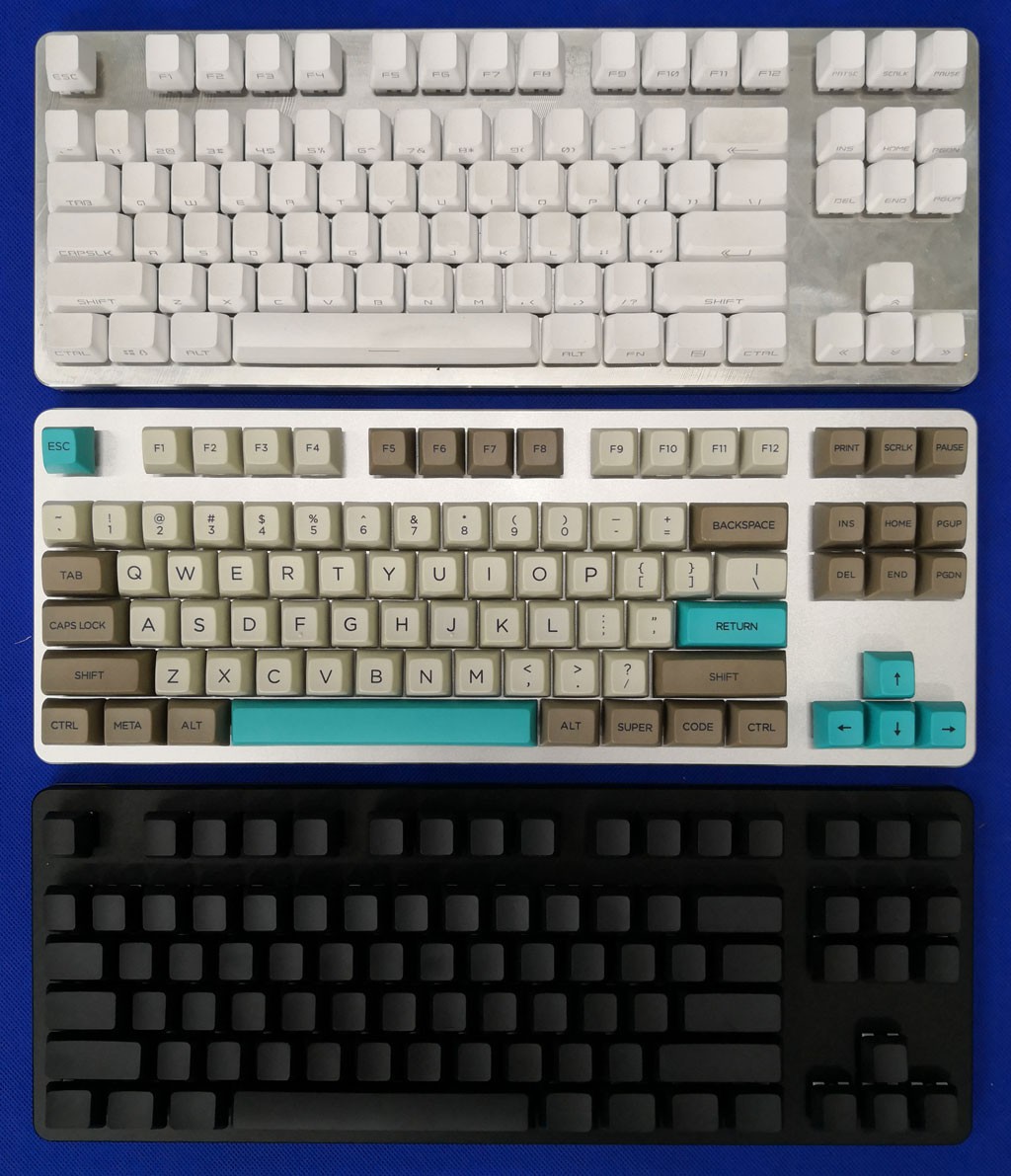
I've decided to try and manufacture 10 K-type keyboards. This is a keyboard designed by Input Club and for me it ticks all the boxes for what a mechanical keyboard should be. There is some drama in the history of this keyboard, where Massdrop manufactured it, then had a falling out with Input Club and released a copy called the CTRL. Input club has moved on to a new keyboard design. So, you can't buy this keyboard and I'm not selling them either. I simply wanted a new keyboard and a manufacturing challenge.
Why the K-type? The design is open source which is the first criteria. Secondly, it has almost all custom parts. You can't just buy the parts and assemble them. Last but not least, I think it's cool and I want one.
So what custom parts do you need?
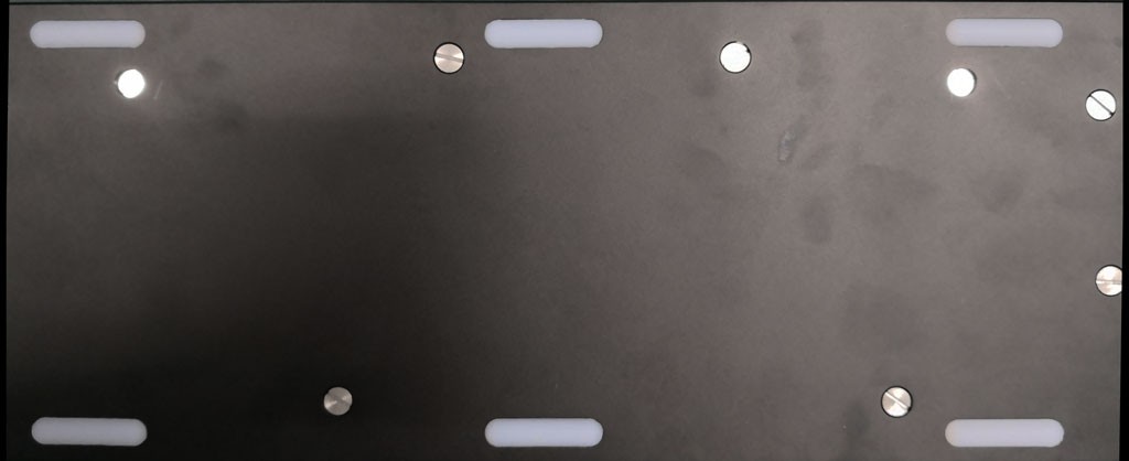
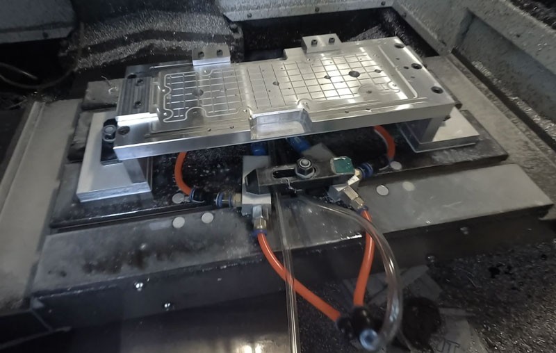
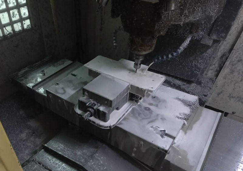
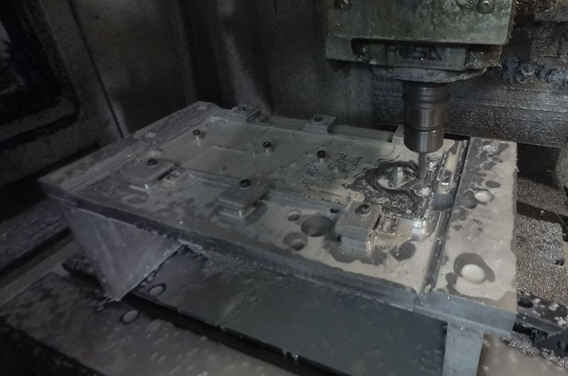
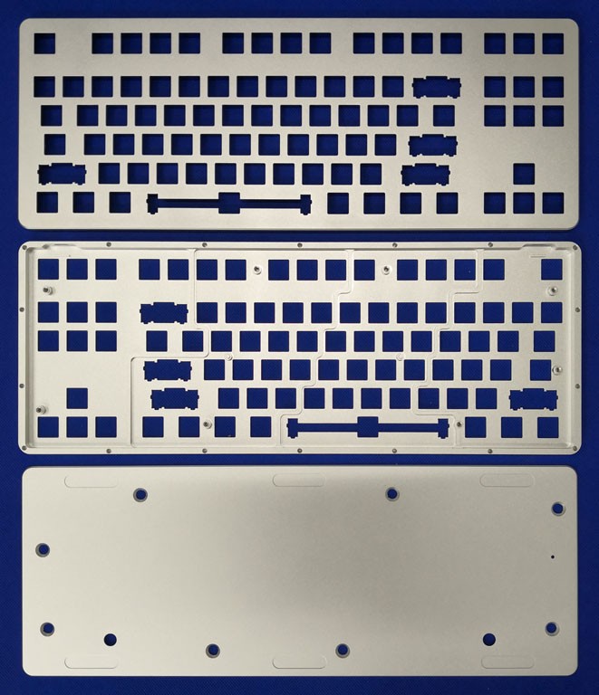
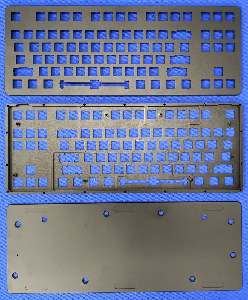
1. CNC Machined Aluminum Case
2. CNC Machined Acrylic Layer
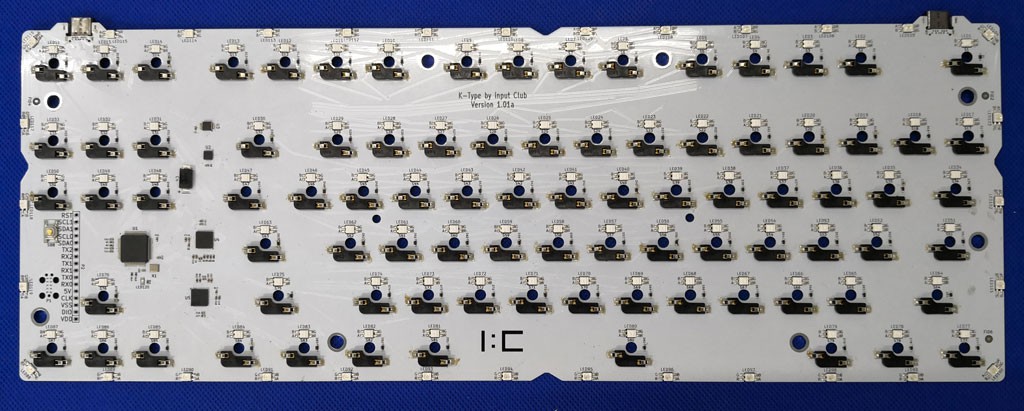
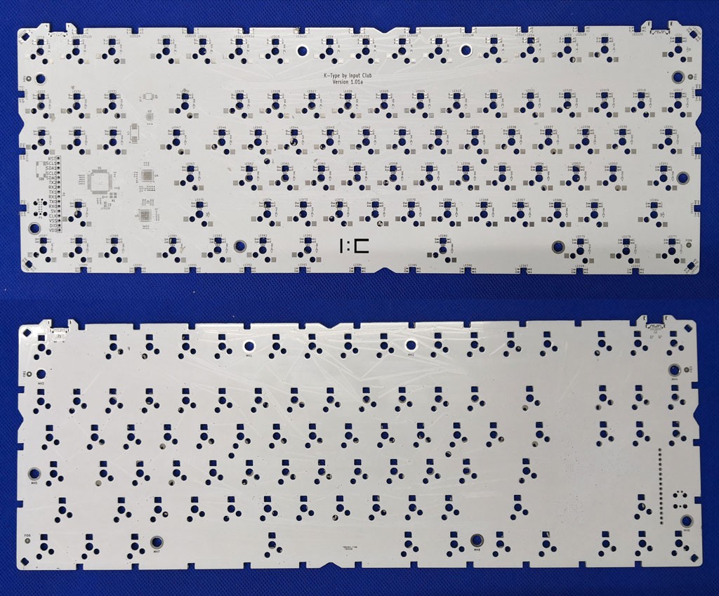
3. Custom PCB
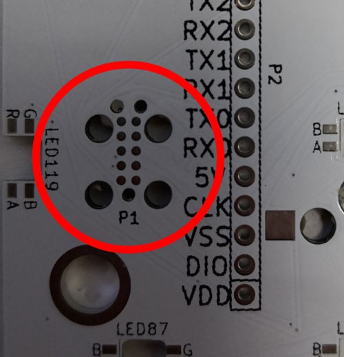
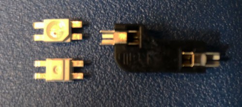
4. Custom LEDs, yup, you heard right, custom. More on this later.
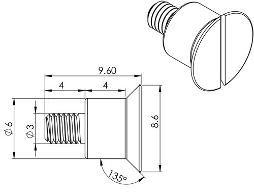
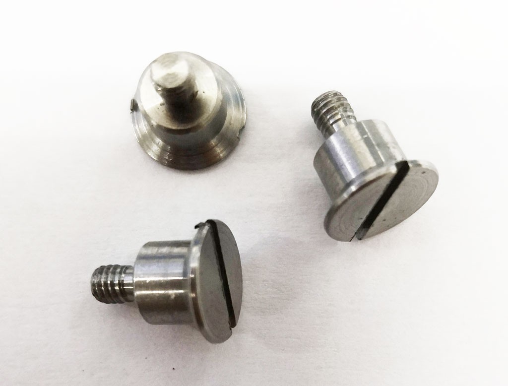
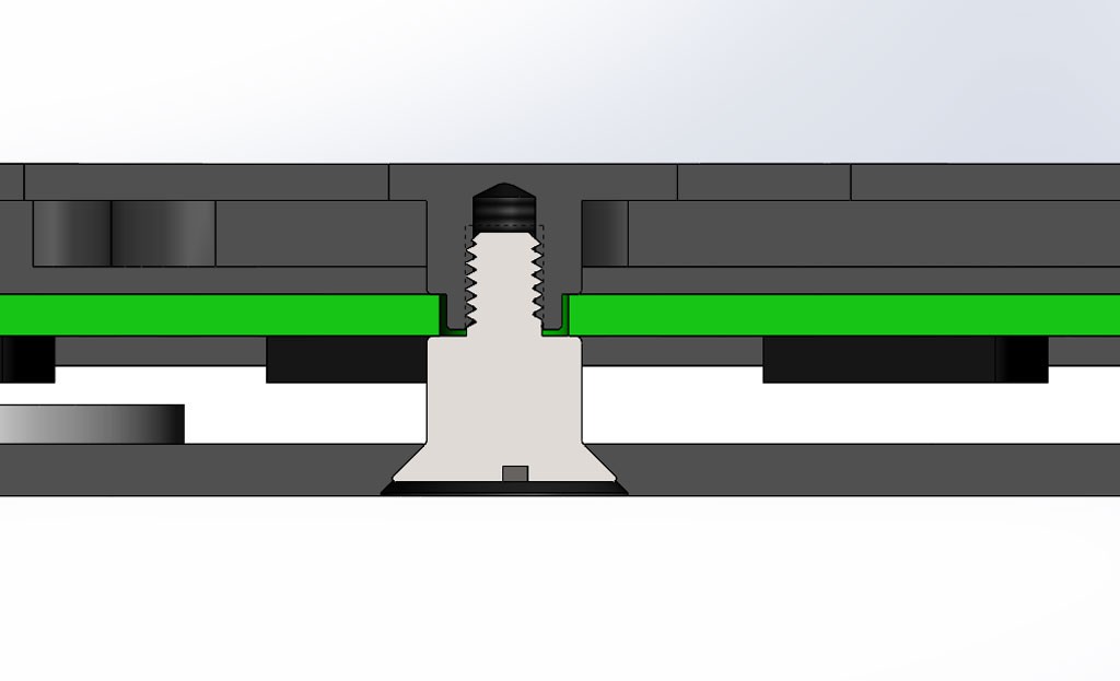
5. Custom screws, believe it or not.
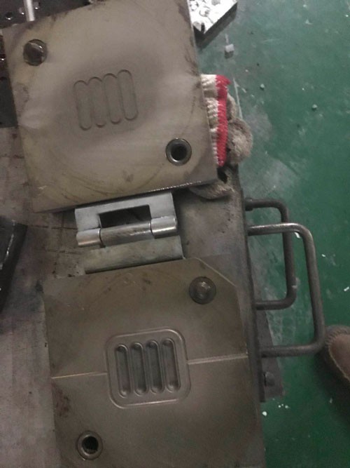
6. Custom Silicone Rubber Feet
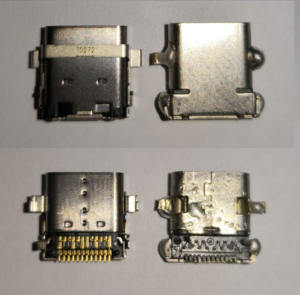
There is also the keyboard switch sockets. They are single source parts from a Chinese manufacturer. That could be a challenge too. What's the MOQ? Can I just call them and buy them?
The keyboard PCB is fairly complicated and many components are 0402, which was not necessary but I've decided to not modify the design for ease of manufacture. I'll use all parts as specified in the design files.
 Dave's Dev Lab
 Cristian
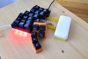
 JohSchneider
 Peter Lyons