INTRODUCTION
I need quite a few solar panel sun trackers to generate as much power as possible from 60 solar panels.
Why? well, we bought a farm in Spain, 120 acres of olive tree garnished paradise.
I'm building a large, off-grid property to replace a derelict farmhouse which is in the mountains of Aragon ...sounds like somewhere out of Lord of The Rings and if I look carefully, I'm sure that I can see Mount Doom somewhere in the Maztrazgo mountains...
Of course, I'm going to need power, lots of it.
I searched the market for a cheap solar tracking unit as my tests in Spain over the last year led me to realise that I need to optimise the amount of power available, especially in the winter. A tracking system will optimise the sun power that I can use and extend the times of day when maximum power is available.
In the area of Matarranya where I'm building (see www.offgrid.casa), there are a number of other off-gridders dotted around, however, they generally use gas or oil for heating and cooking plus around a dozen solar panels for basic electrical requirements. They end up running their generators for much of the winter and that goes against my principle of no carbon based fuel brought to the land. Carbon-based wine is a different matter, however. That is allowed by the truck load.
My guiding light is that I want my house to be really, properly and totally self sufficient - i.e. all electric, powered by a combination of solar and some wind. Basically, I want to be different. Also, I don't want to have to haul off into town which is 10 miles away down a dirt track just because I run out of cooking or heating gas.
In the summer, folk just put up with the heat as they generally don't have enough power for aircon. However, I'm going to use reversible air source heat pumps with under floor piping to heat the house in winter and cool it in summer. This means that the concrete floors become a thermal battery and I can either put heat into the floors ar remove it during the day when power is plentiful and cut it off at night to avoid battery drain. A huge hot water tank also run off a separate air source heat pump will be another thermal battery - additionally, a pair of immersion heaters will allow me to heat the water to around 85 degrees celcius (185 fahrenheit) whenever there's spare power. I'll also automatically switch on the charging power to my Tesla if there's any power left over - see, I don't even need fuel for the car...admit it, you were wondering if I was actually a hypocrite with a planet destroying gas guzzler. My son calls it "electric smugness" and, apparently, I have it in spades. Can't see it myself though.
Tests have been done with a neighbour who has now finished his house. Last winter he kept his house at a steady 22 degrees celcius (72F) and ran his electrics all winter from 15 x 260W panels. Obviously, 6 inches of insulation in the walls and floors helps. However, once the house has attained the correct temperature, it doesn't need much input.
SOLAR TRACKING
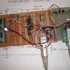
My early trials just used a single axis tracking system. The first video shows the first tests in my workshop. There's also a bit of a tour of the 8-channel solar power monitor and mains inverter interface if you're interested.
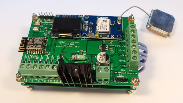
The finished prototype
My solar tracking metalwork is fairly simple. It uses eight cheap, stainless steel ball bearing hinges, some steel and two 4 inch (100mm) linear actuators. The initial prototype was in aluminium, but it's such a pain to weld, that I have moved to mild steel. You don't actually have to weld it together as you can just use...
Read more »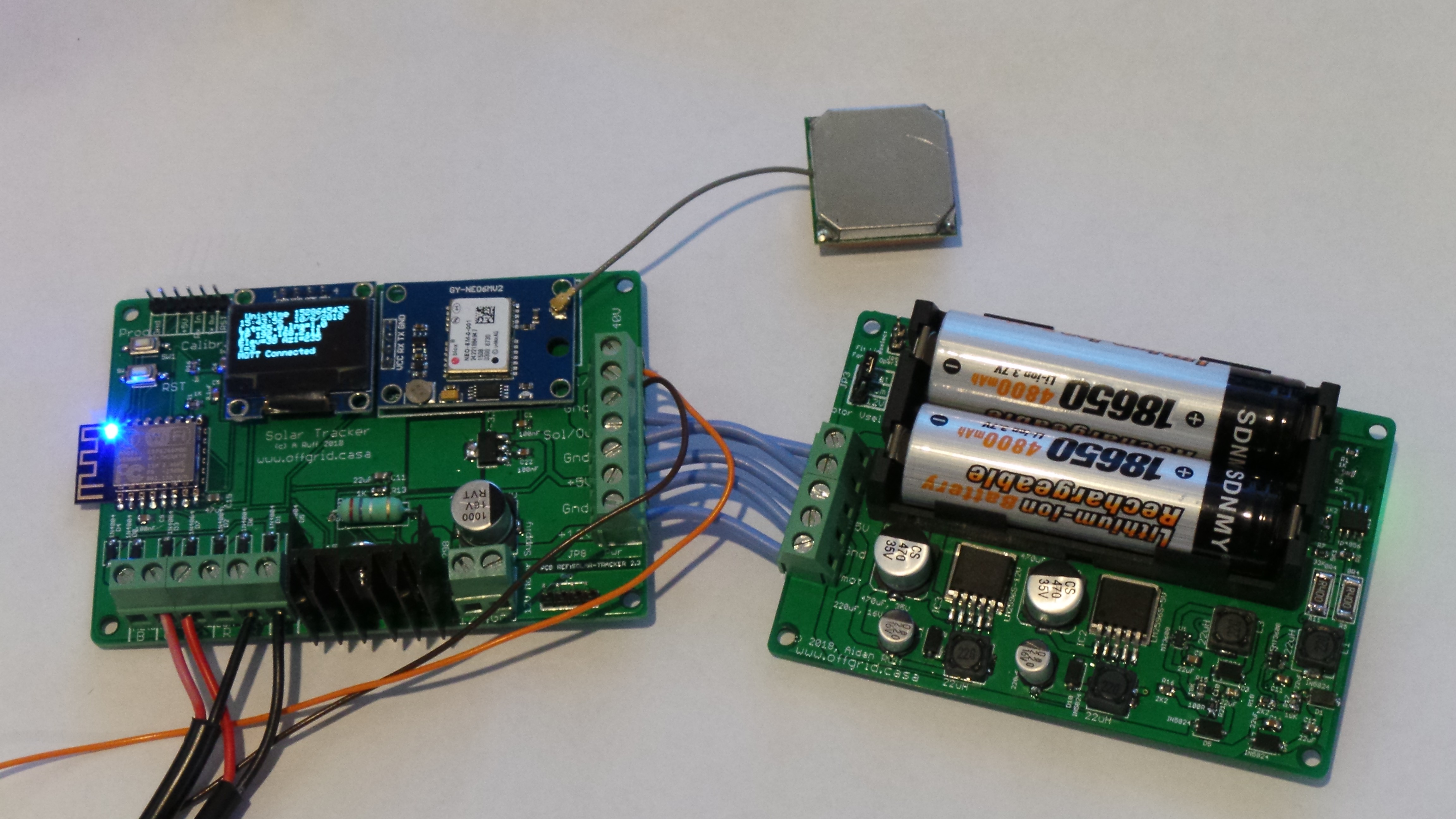

 MCenderdragon
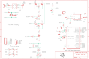
 Arpit Singh
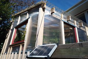
 Sam Griffen
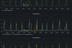
 Turo Heikkinen
That's a really good point! I've added the Arduino code to the files section. Bear in mind that this runs on an ESP8266 so you'll need to add that processor to your environment...really easy.
The list of libraries are in the <include> section at the beginning of the code file