0%
0%
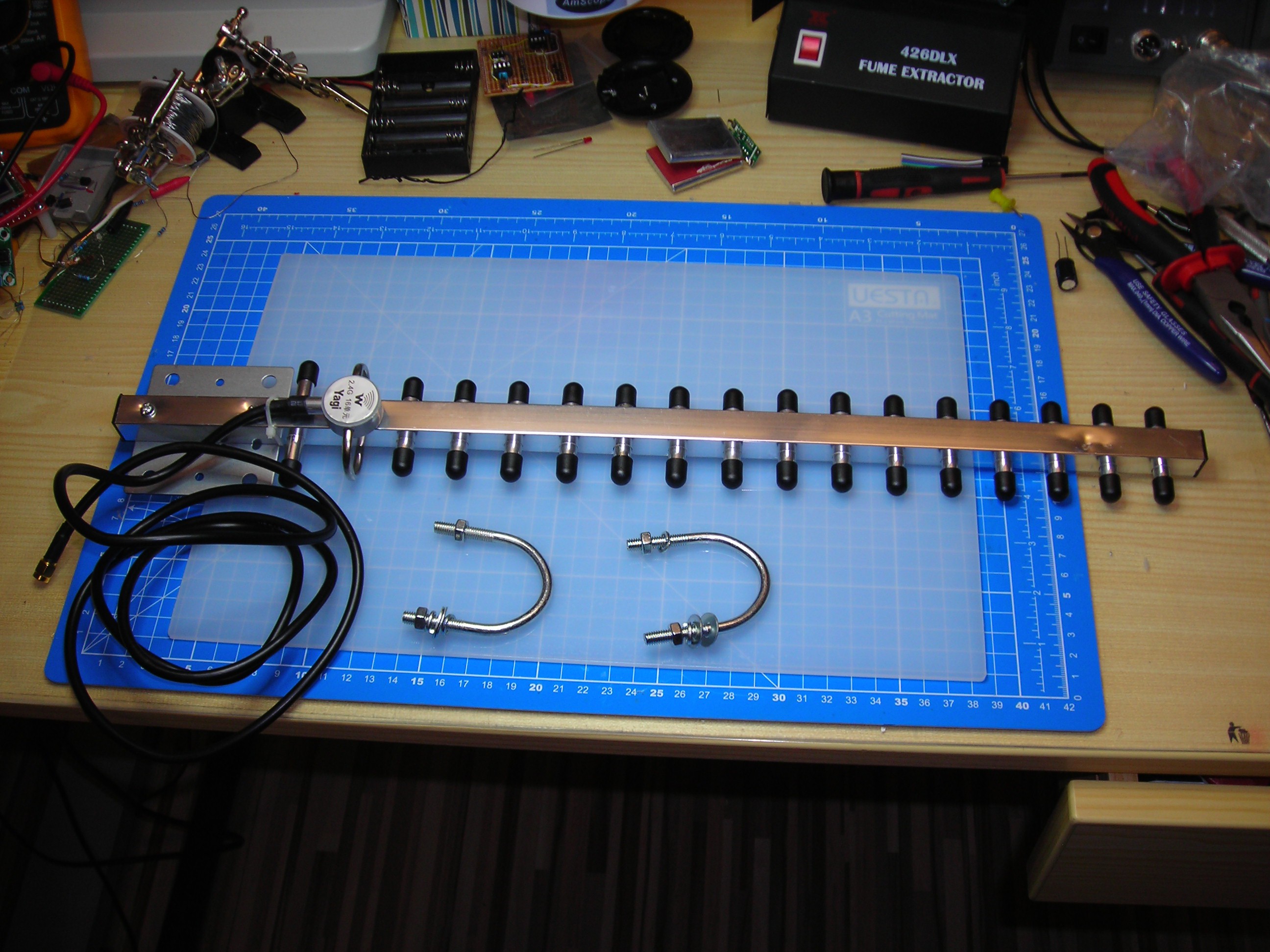
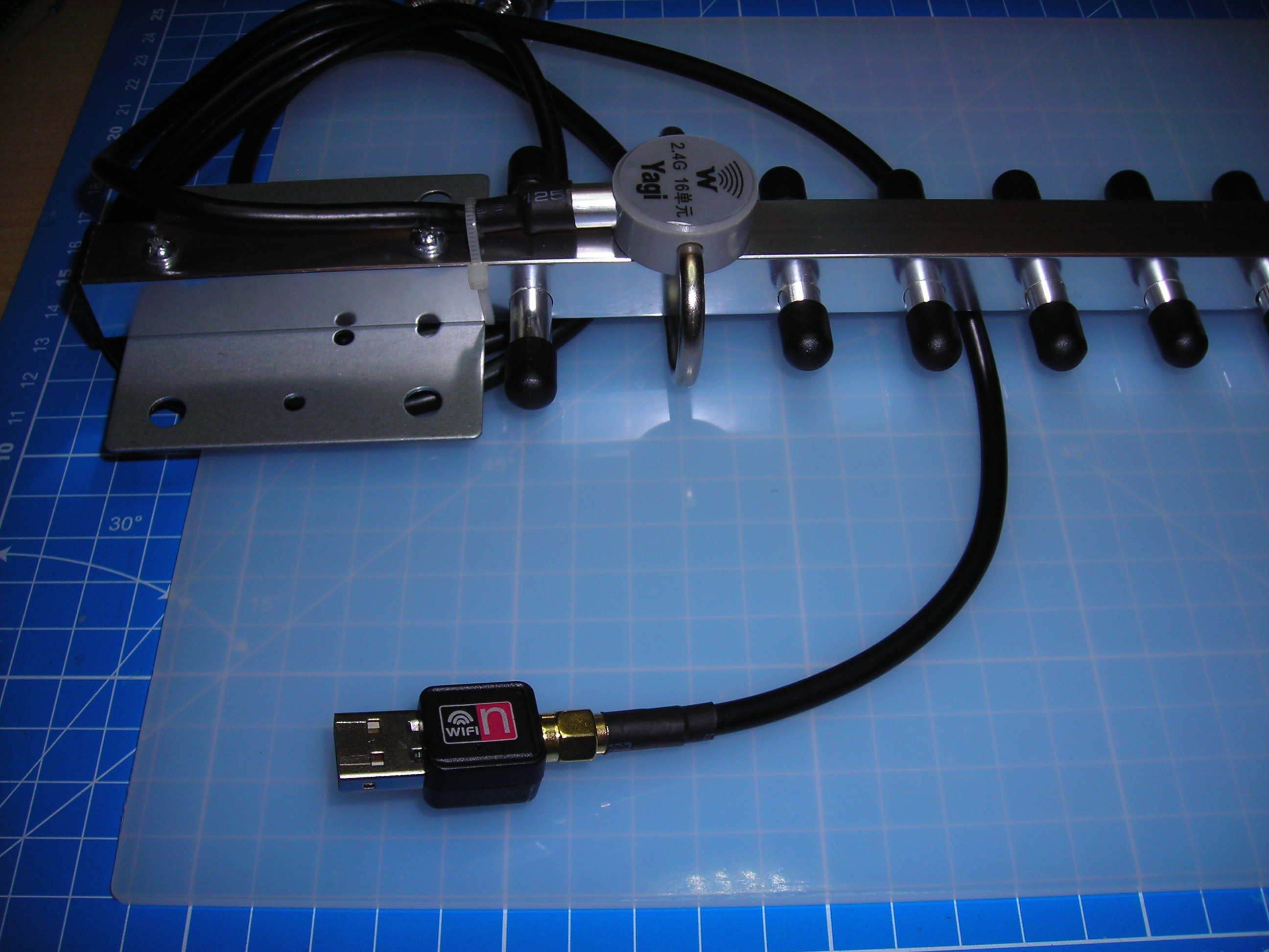
Dodgy 2,4 GHz WiFi-Yagis from China
Rework of one (actually 2) non-working cheap 2,4 GHz WiFi-Yagi(s)
Become a Hackaday.io member
Already have an account? Log in.
Just one more thing
To make the experience fit your profile, pick a username and tell us what interests you.
Pick an awesome username
hackaday.io/
Your profile's URL: hackaday.io/username. Max 25 alphanumeric characters.
Pick a few interests
Projects that share your interests
People that share your interests
 Ruediger F. Loeckenhoff
 Colin Alston
 Morning.Star
 matthewkleinmann
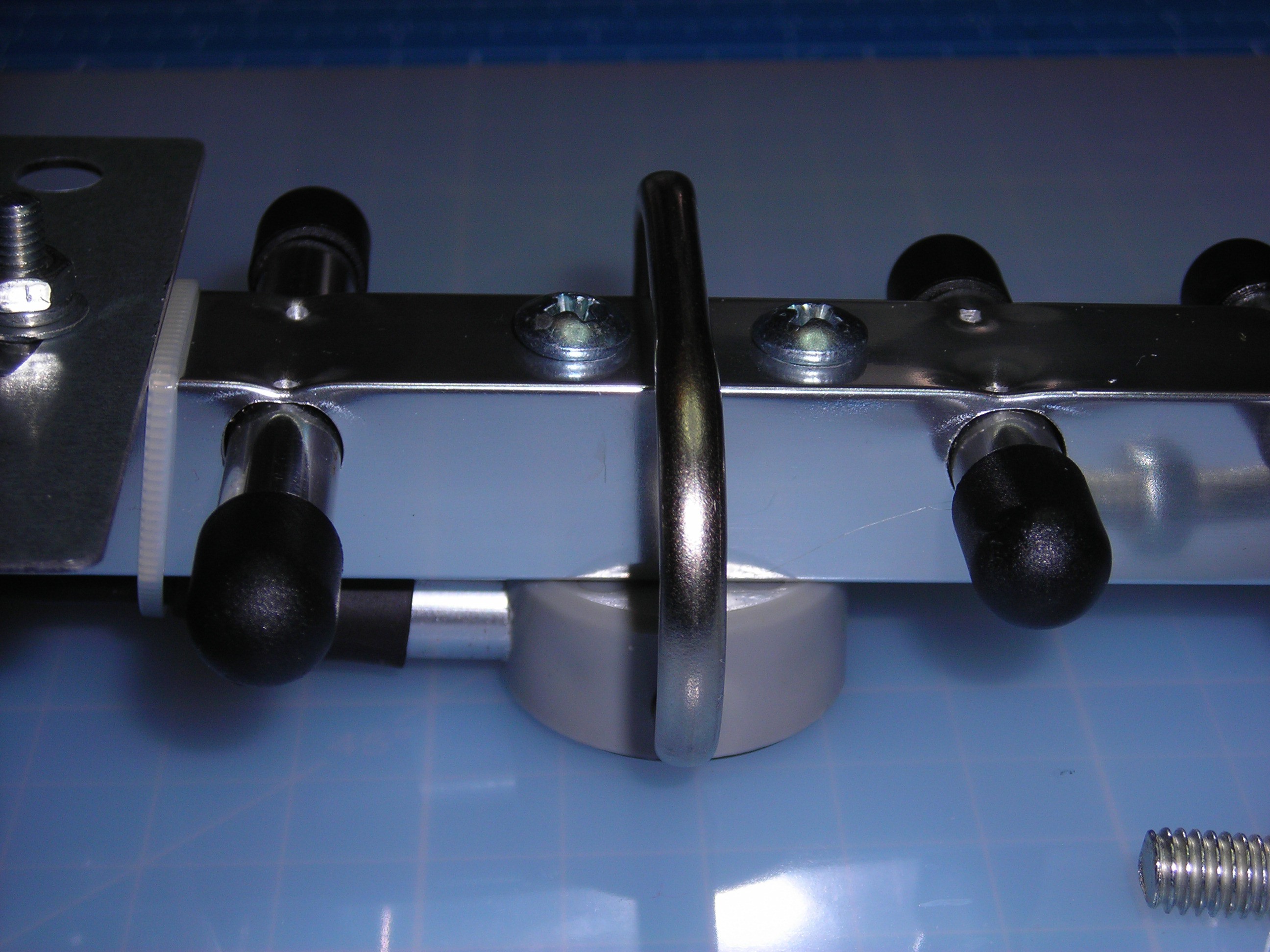
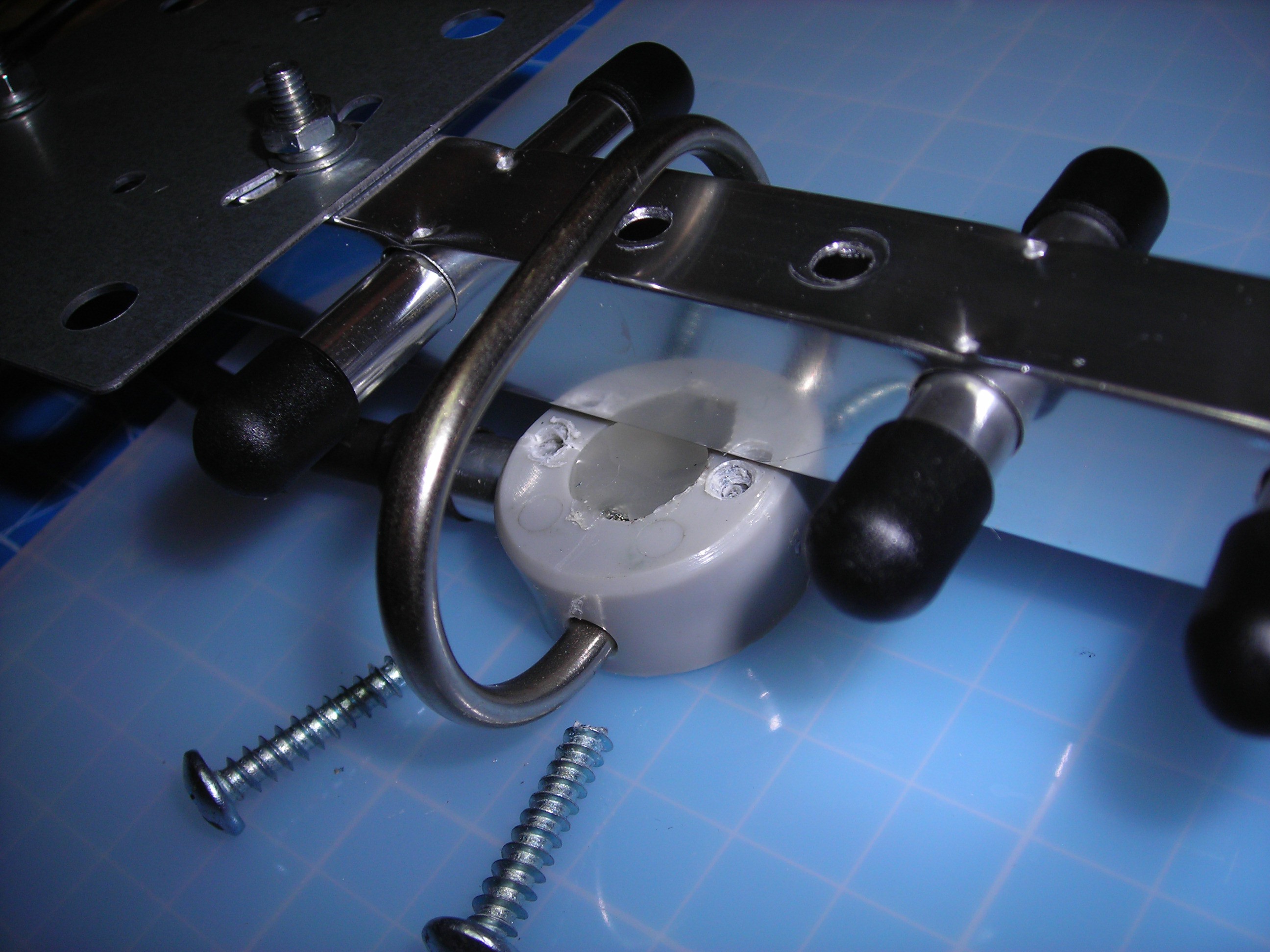
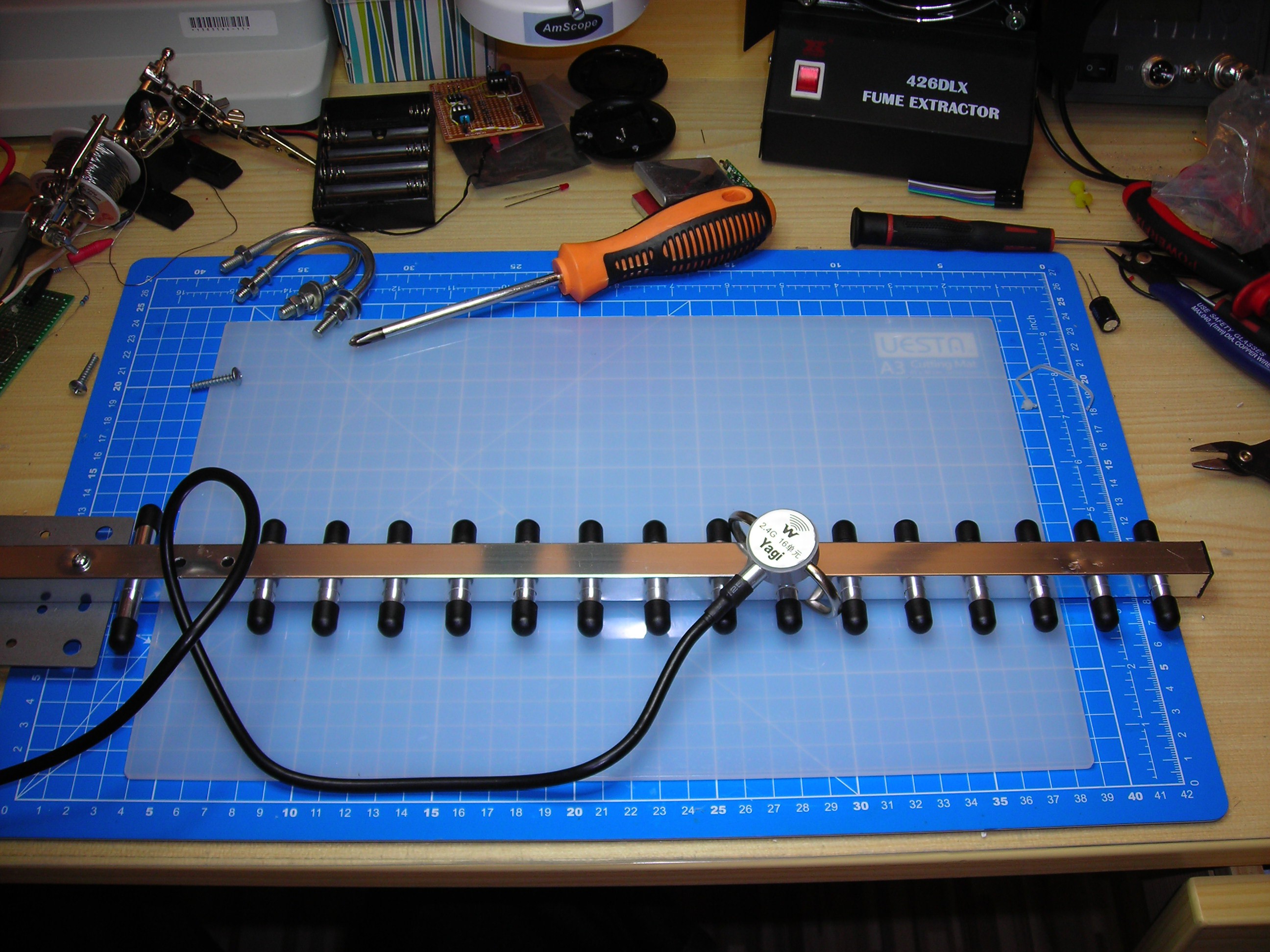
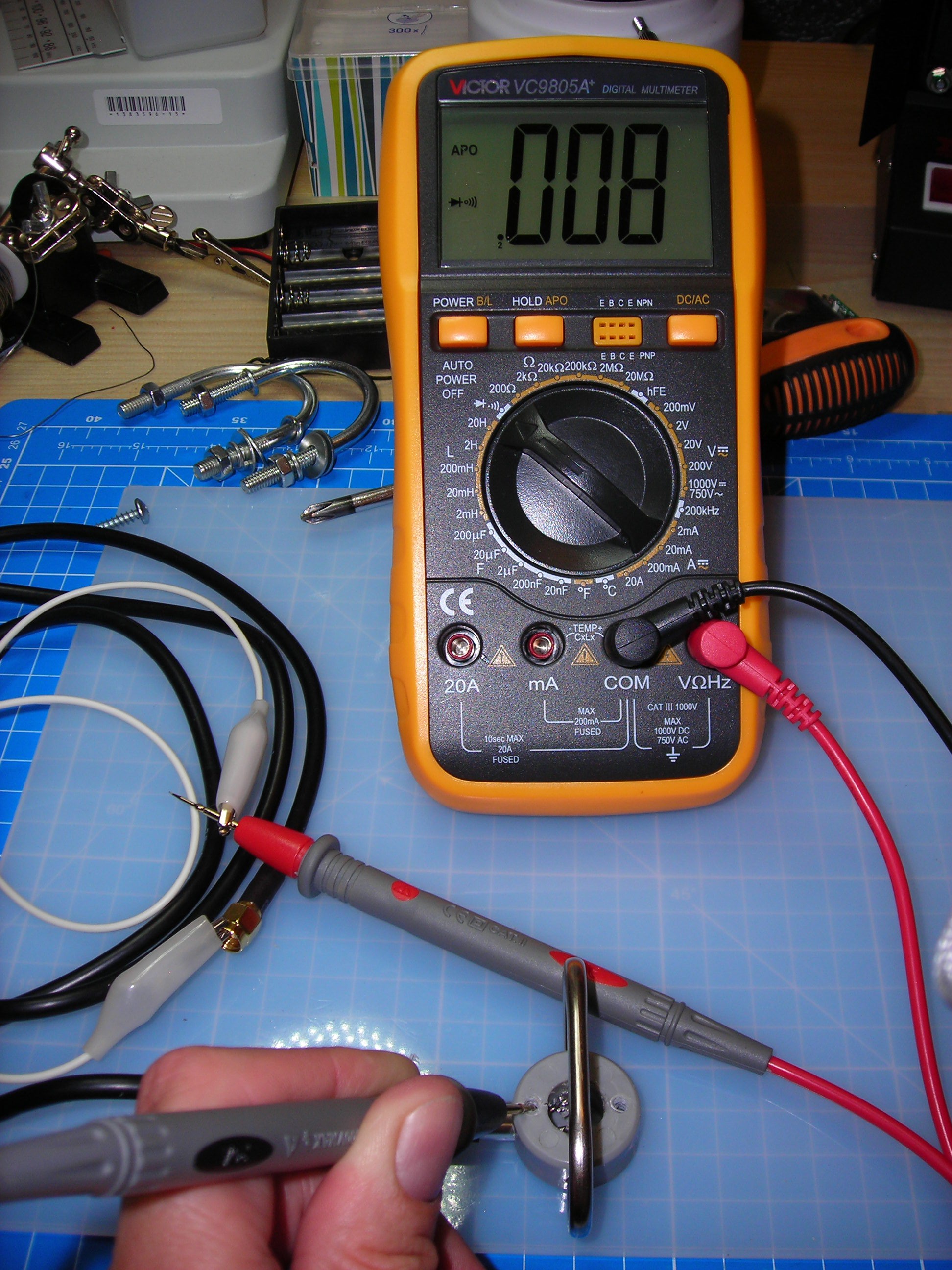
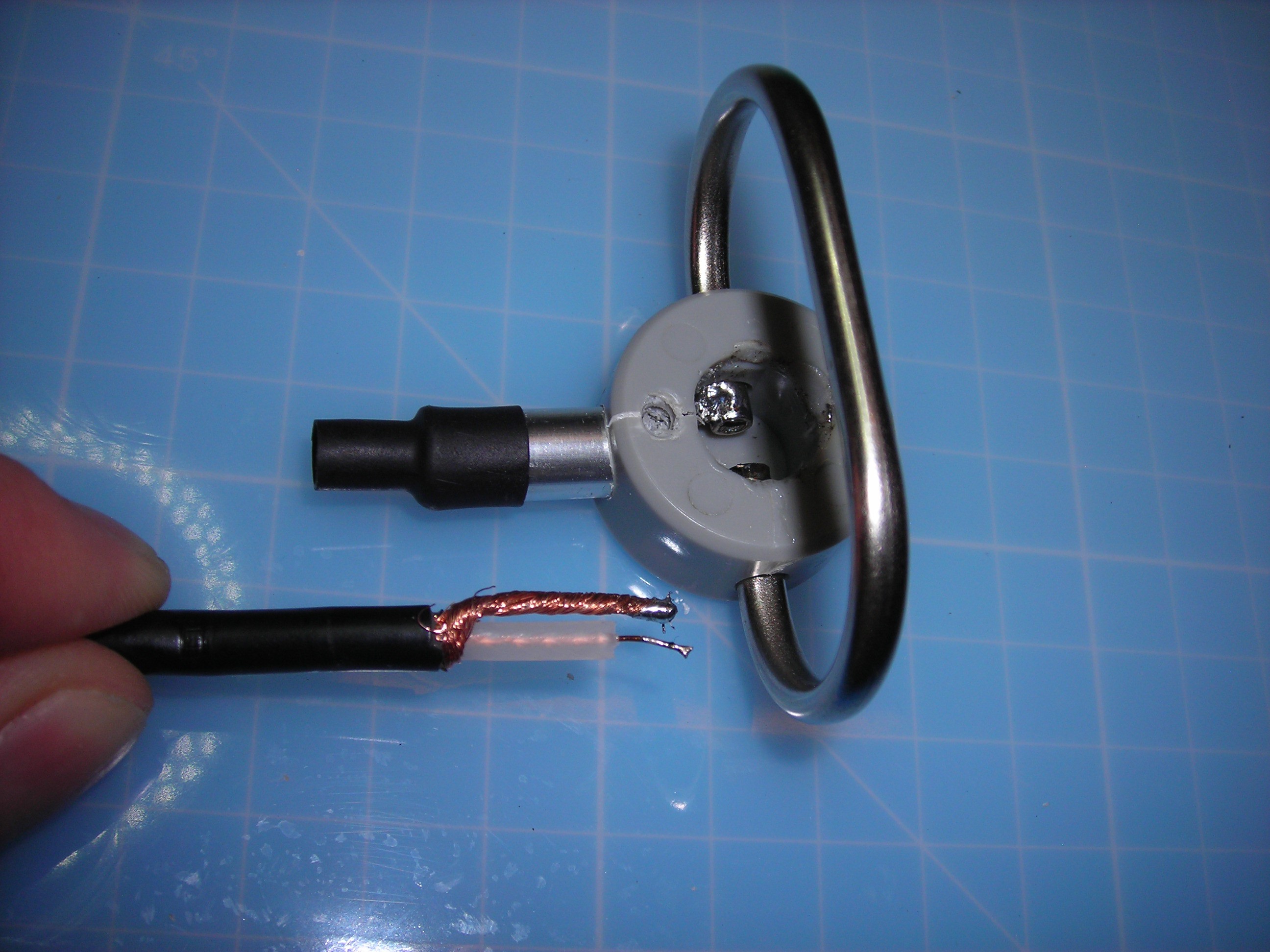
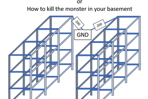
Thank you for publishing your experencies and sharing with us. Before I found your analysis, I disassembled an identical antenna. With the glue removed, I found the center of the coaxial outlet connected to one end of the dipole, the shield connected to the other end. I measured the antenna in this configuration to have a 10 dB gain over the standard router antenna (a 120 mm stub). The mounting plate was removed during this measurement.
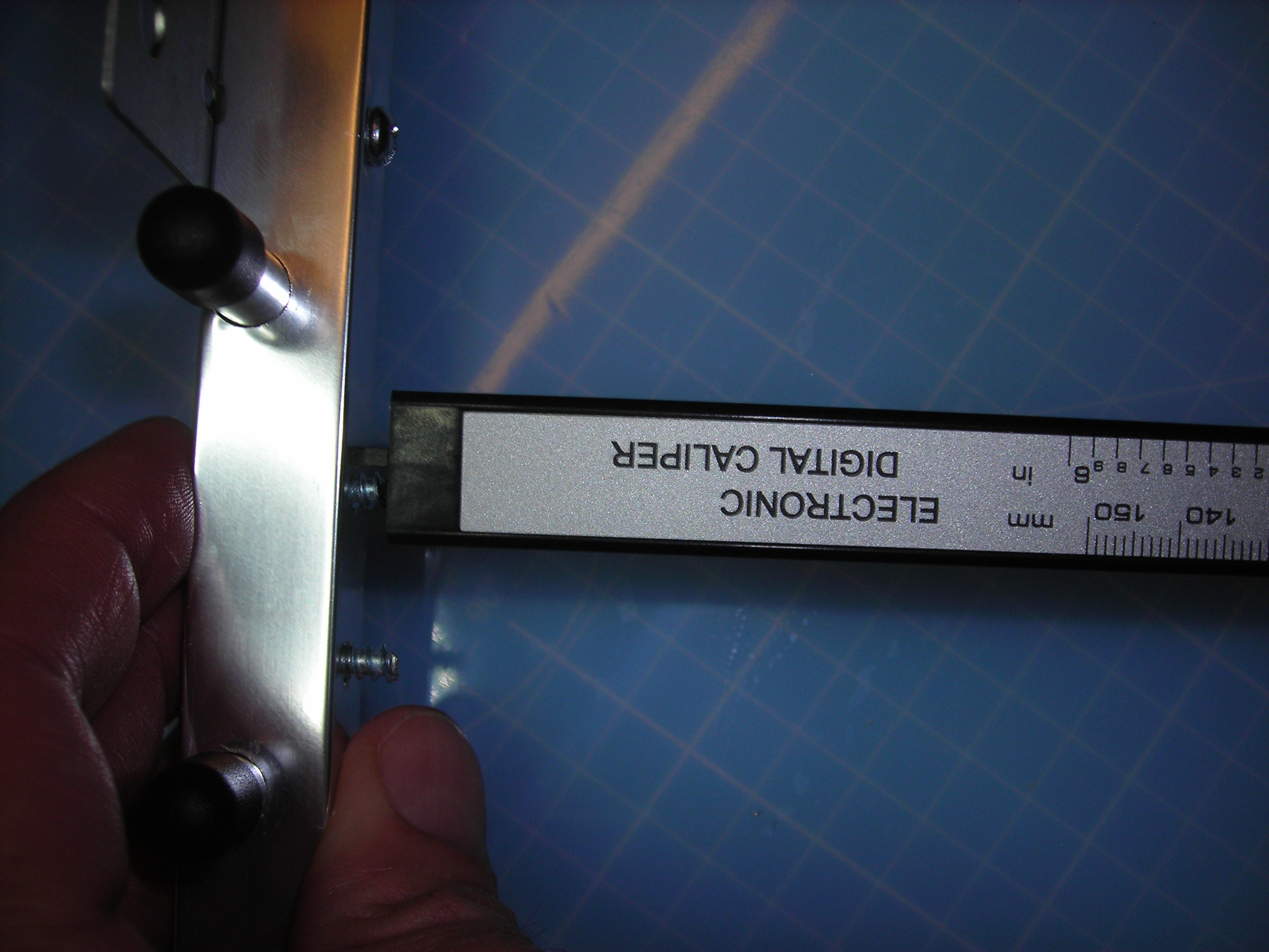
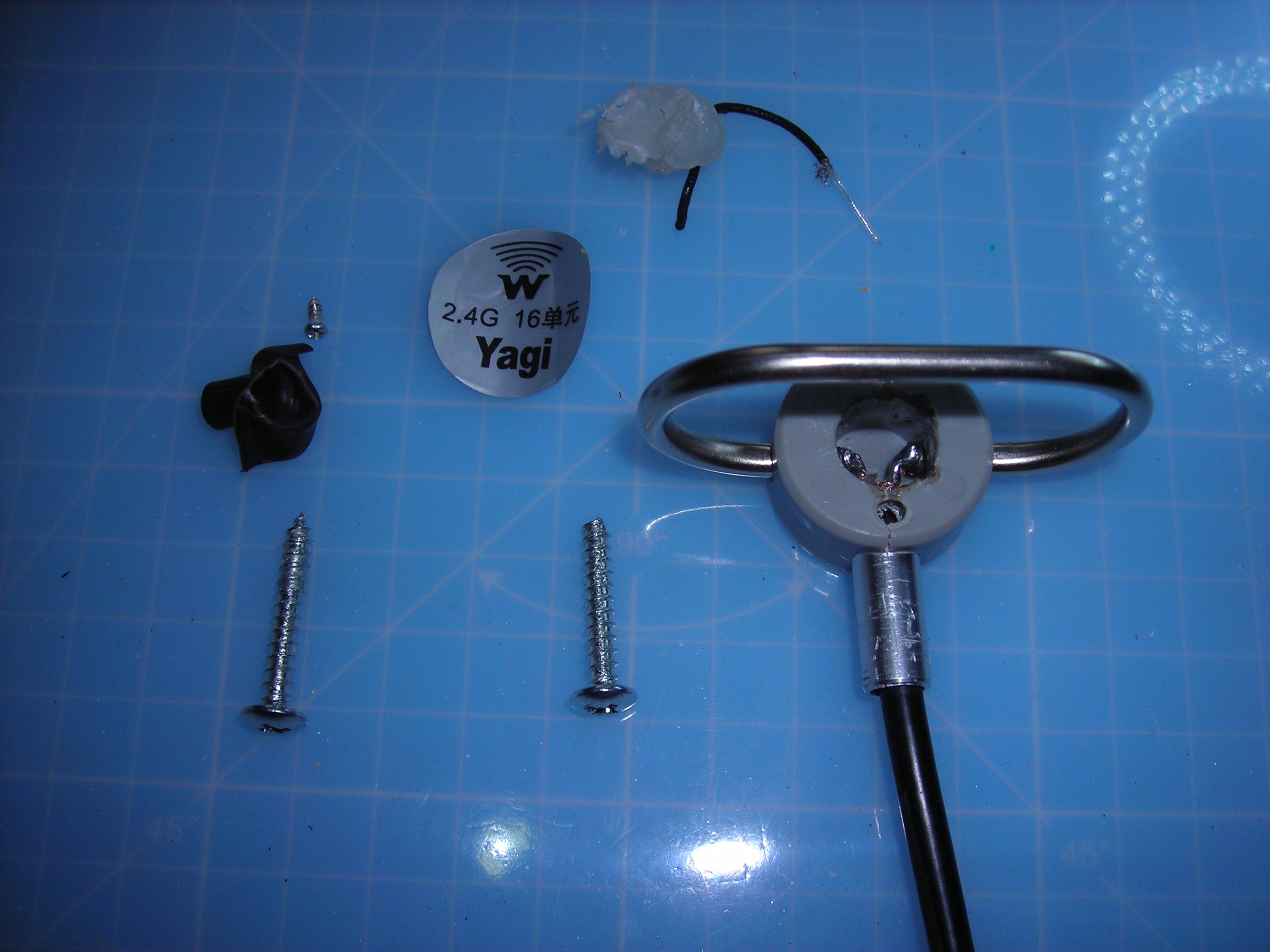
I also found a 'piece of black wire' embedded in the glue. Close inspection showed that this is actually a piece of coaxial cable, 1,2 mm o.d. and just 40 mm long. Then I made a calculation of the length of a balun needed to match the folded dipole to the coaxial outlet cable of the antenna for 2400 Hz. For a coax cable with a velocity factor of 0,66, this length should be 41 mm. So my guess is that the antenna is designed with a proper balun, but the assembly is sloppy and repair is needed. I am stil working on the antenna...