 Involute
Kilonomicon will have at least two modes of operation. In one, it will play brief patterns of sounds on a subset of the relays (anywhere from one to, say, 100), separated by random intervals of several seconds up to a couple of minutes. In the other, it will play a three to four minute composition that will enlist all the relays (at least for some sections). The first mode will be the default, with the second kicking in every hour or so.
There may be an additional mode allowing one or more people to "play" Kilonomicon in real time via some sort of MIDI interface. I'm hoping to at least partially fund Kilonomicon through Kickstarter, in which case this additional mode will be a stretch goal. Another stretch goal may be to commission actual composers to create the mode 2 piece(s), though I've already located a couple of composers willing to give it a shot for free due to the novelty of Kilonomicon.
I hope to display Kilonomicon at music festivals (e.g. Coachella, Lollapalooza, Electric Daisy Carnival, etc.) and science museums around the country (or world, if someone funds the travel) for a year or two, and then find a permanent home for it.
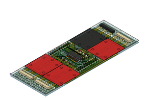
Given it will be moved around a lot, I've decided a modular structure will be the best approach. While this will require assembly and disassembly, it makes crating and shipping much easier than it would be for a monolithic piece measuring roughly 10' tall by 10' wide by 6' deep (that tipsy woman in the render is 5'9" tall). It also makes initial construction much easier since I can build the modules at my leisure and then rent a space for a few days to do the final assembly for testing.
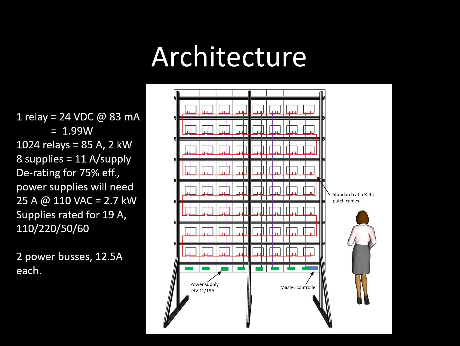
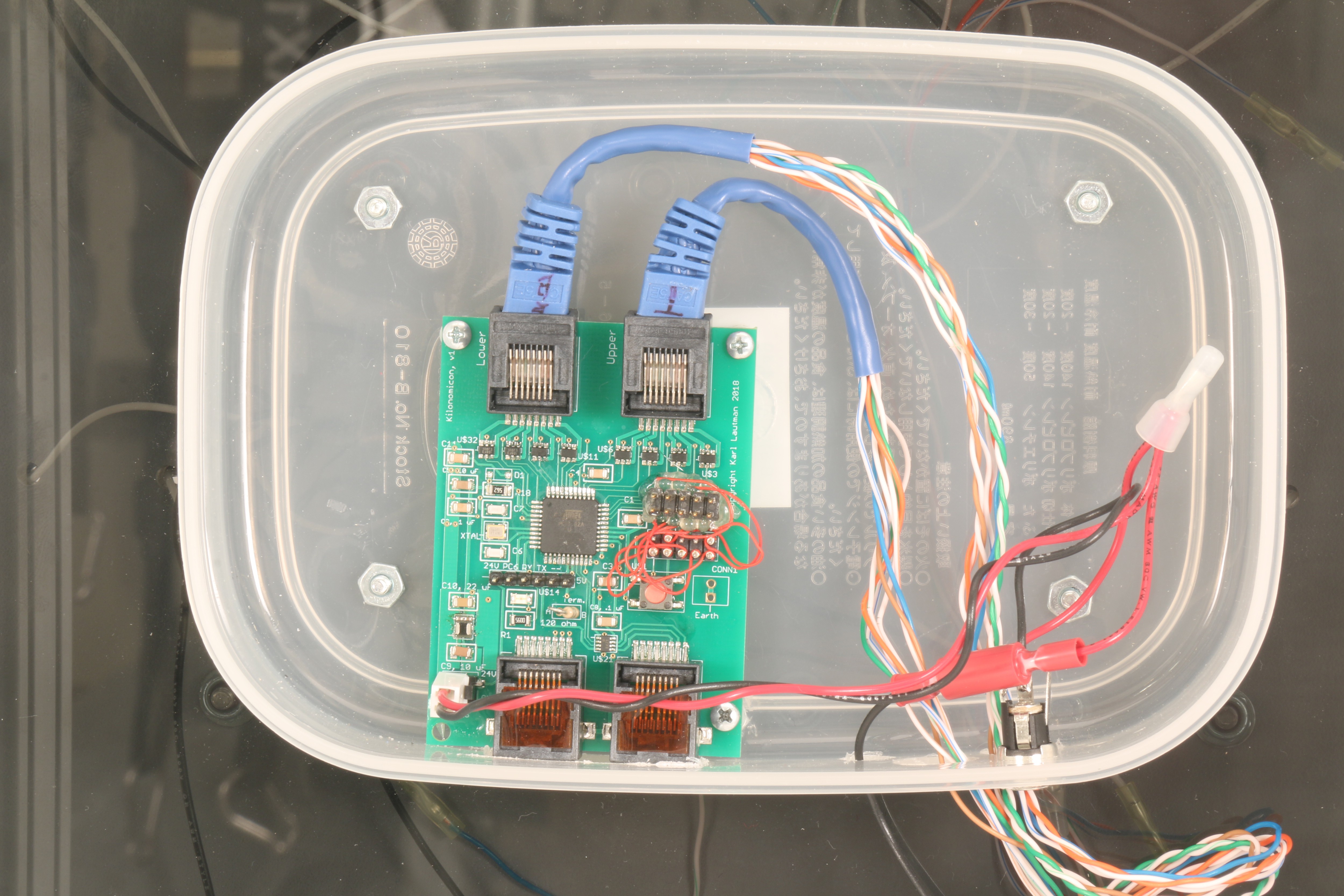
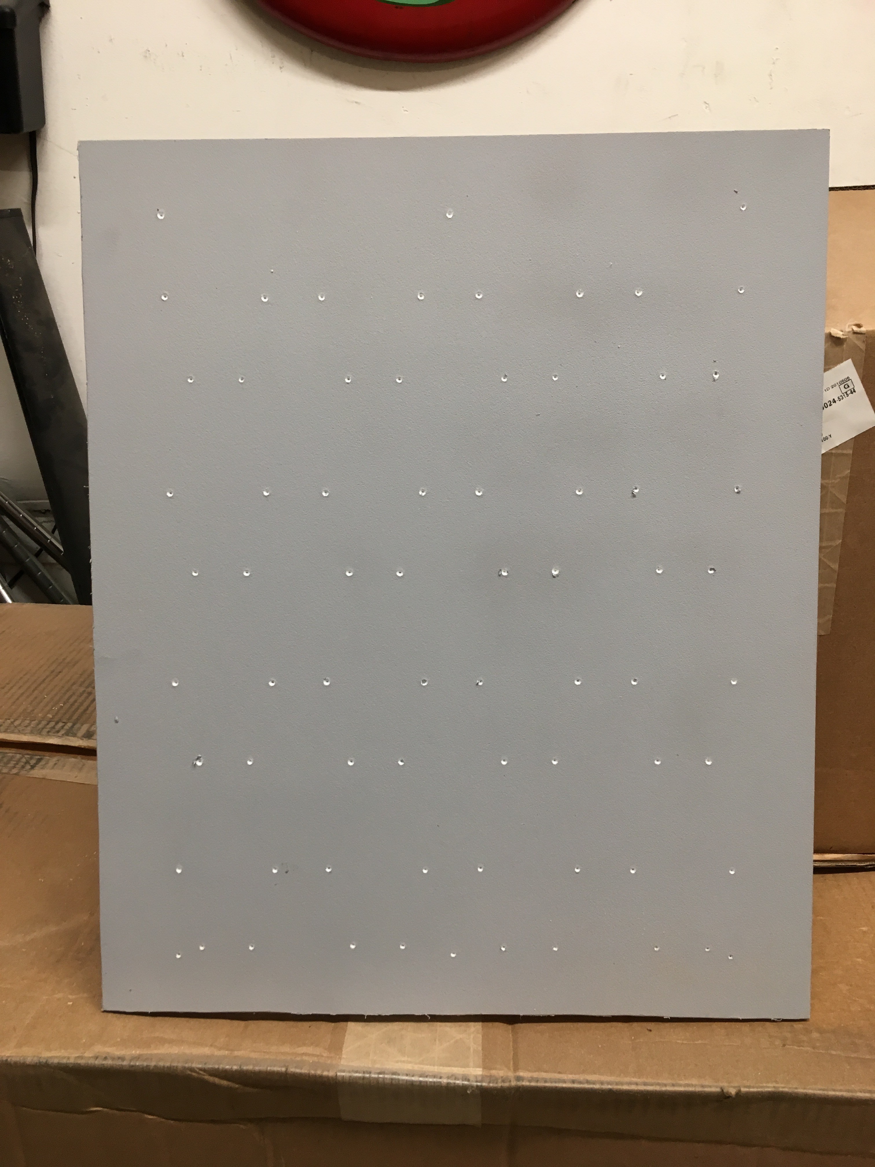
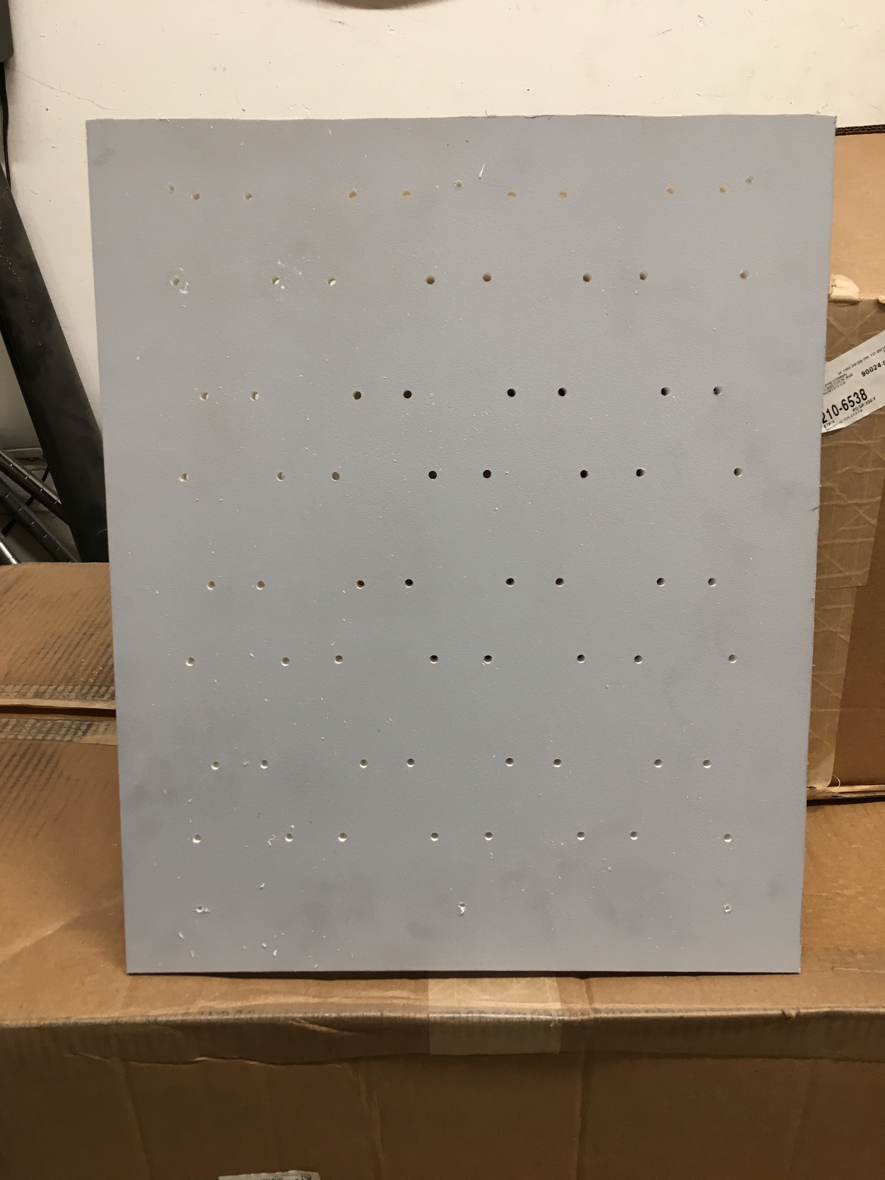
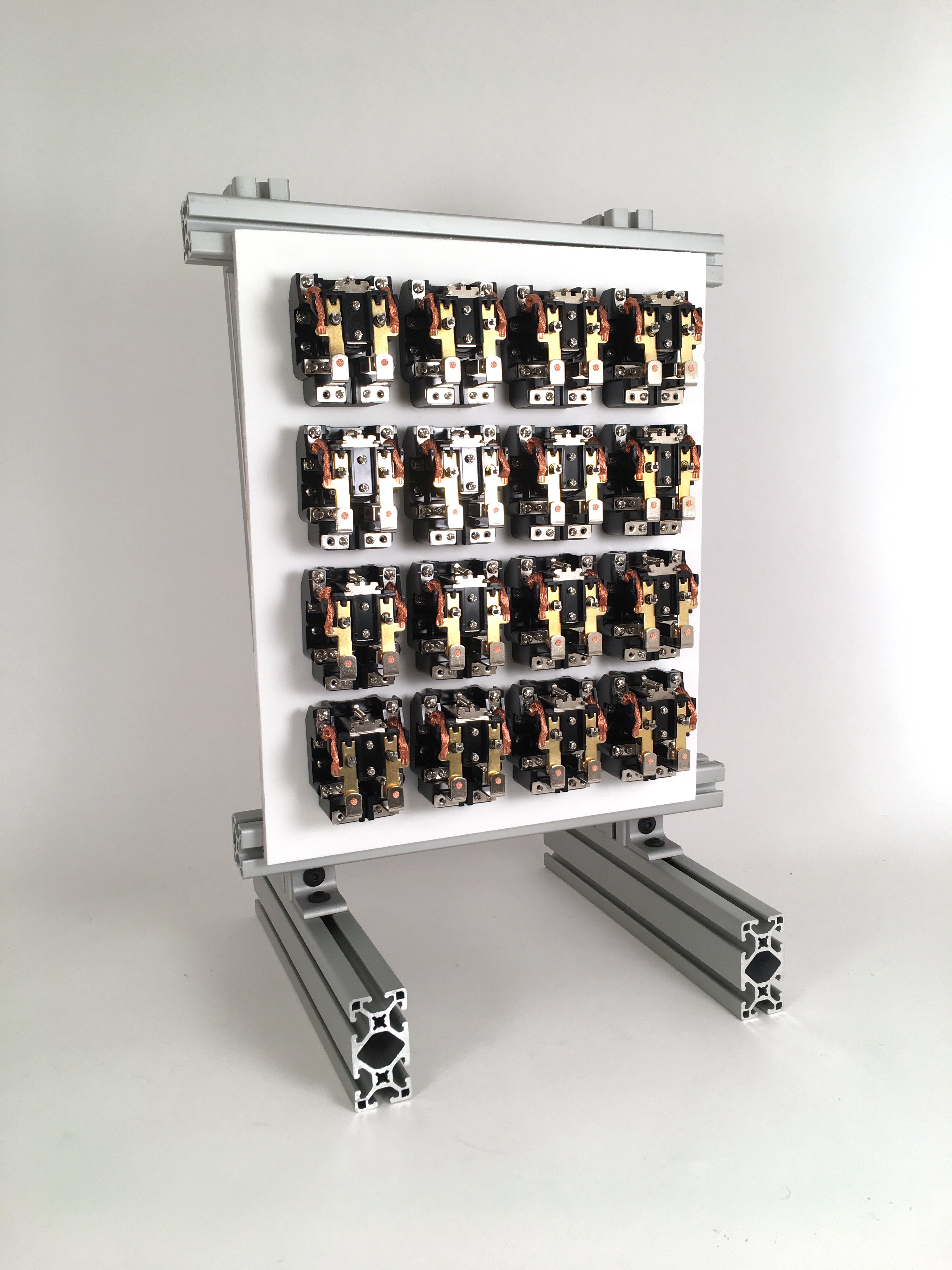
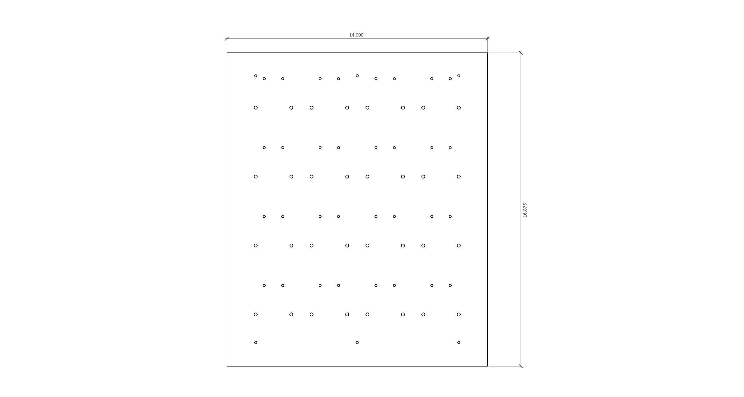
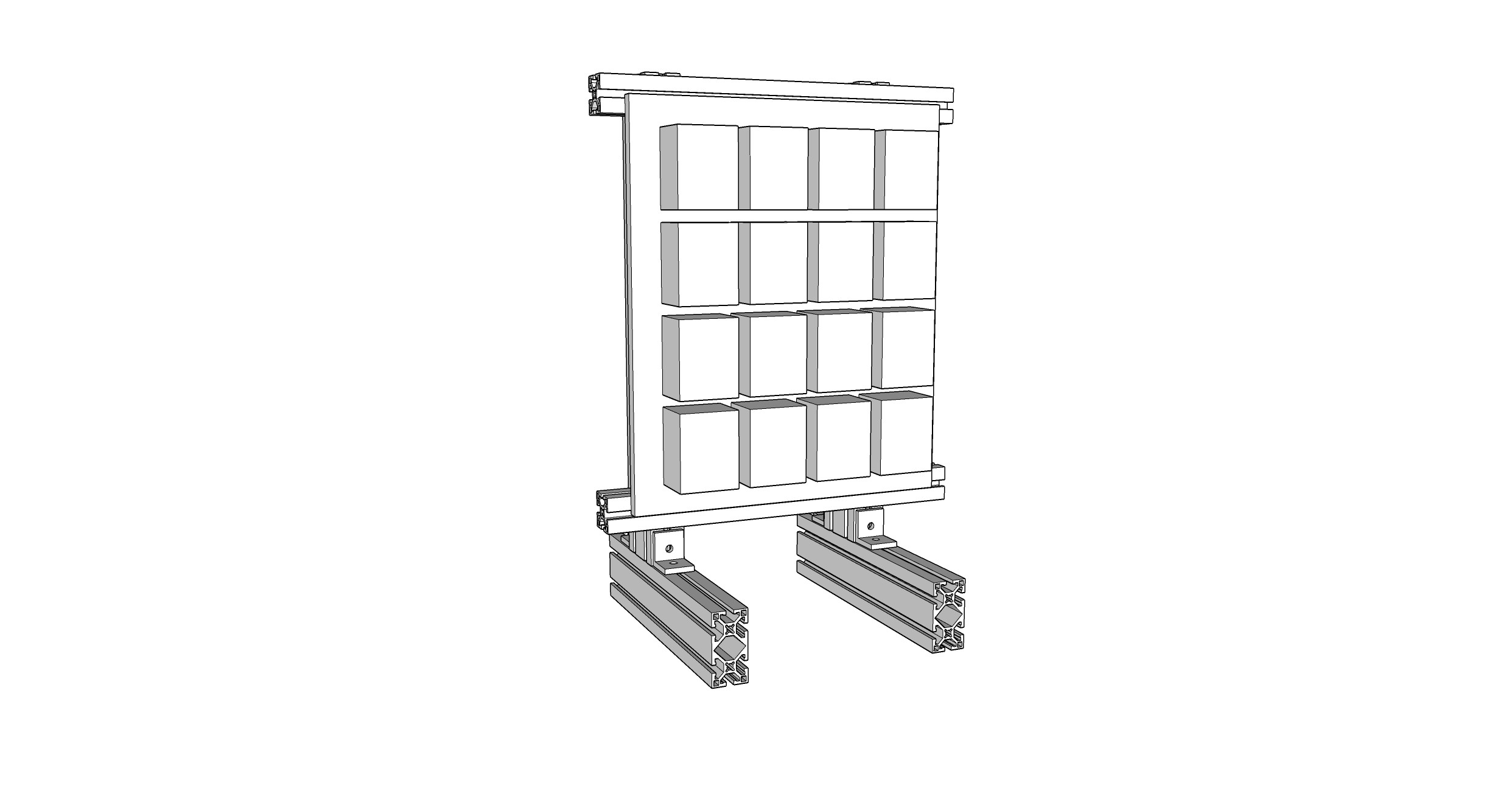
The architecture consists of 64 electrically identical modules, each containing 16 24VDC relays in a 4x4 array with .5" spacing, and a controller board (based on an Atmel (Microchip?) ATMega32A). These modules will be assembled in an 8x8 array. Mechanically, the inner 36 will be identical (12"x12"x.5"), but the 28 forming the perimeter will be sized differently to provide the border you see in the render. The modules will be networked together via RS485 and controlled by a single master controller board which will read relay configurations from on-chip flash and an SD card and spit them out onto the bus as 4-byte packets (1 start byte + 1 address byte for the associated module + 2 configuration bytes (16 relays = 16 bits = 2 bytes)).
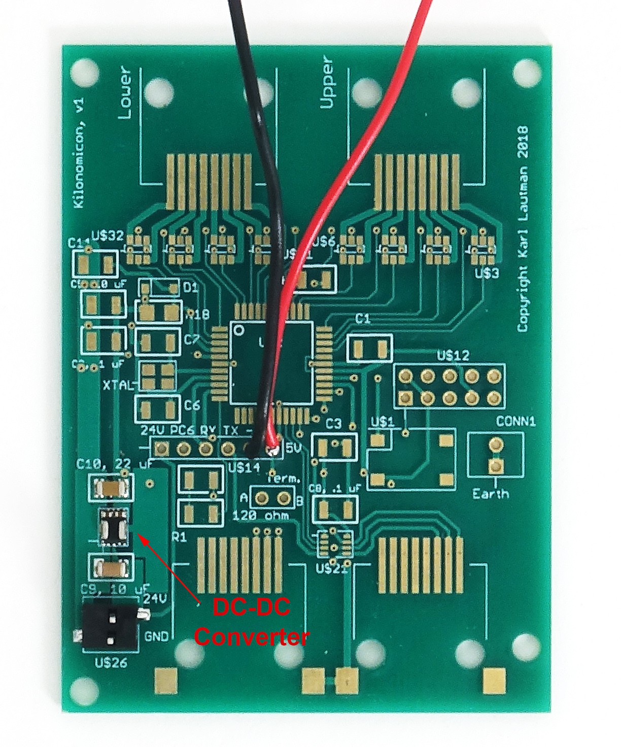
Each relay draws 83 mA, leading to a total system power draw (including power supply efficiency) of 2.7kW. This will be divided among eight switching power supplies. Here's a sketch:
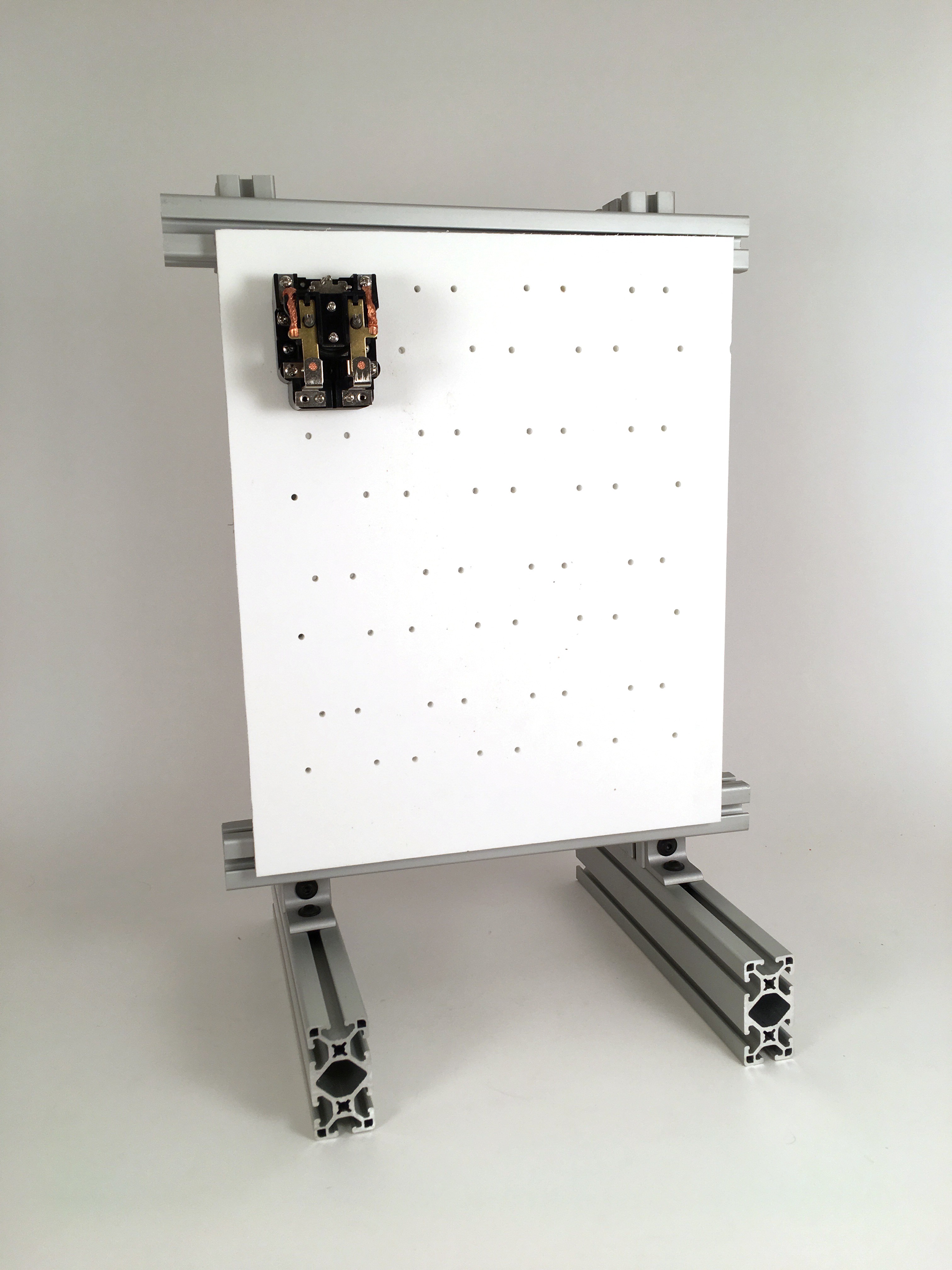
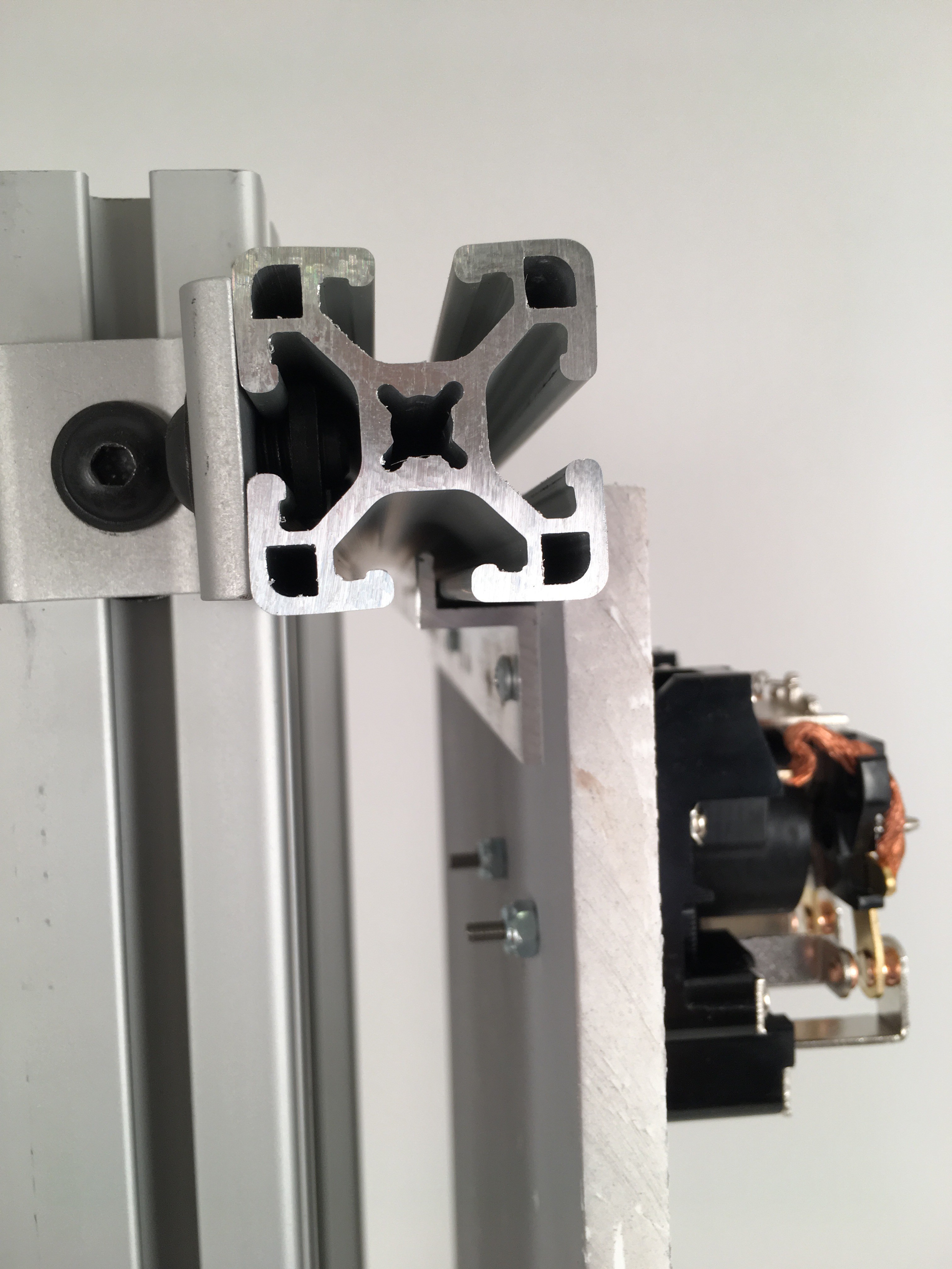
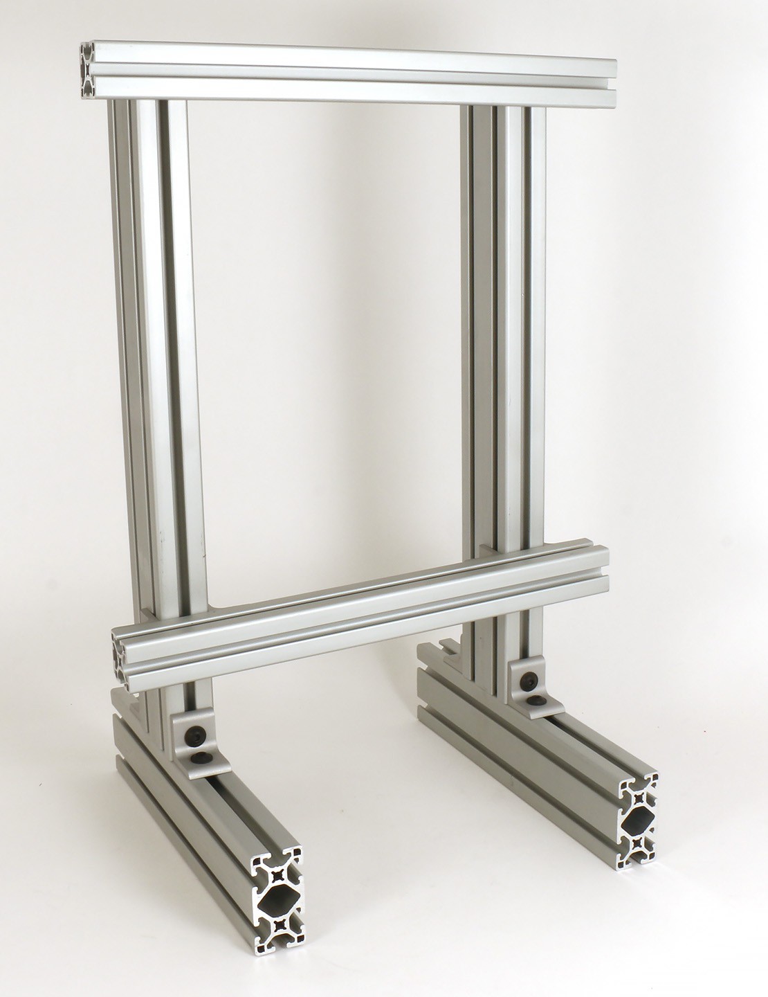
The frame will be made from 80/20 extrusions. The design is still being fine-tuned (e.g. the joint between the three legs and three horizontal "feet" needs to be reinforced). I intend to perform wind force analysis to determine how strong a gust it can withstand before being blown over.
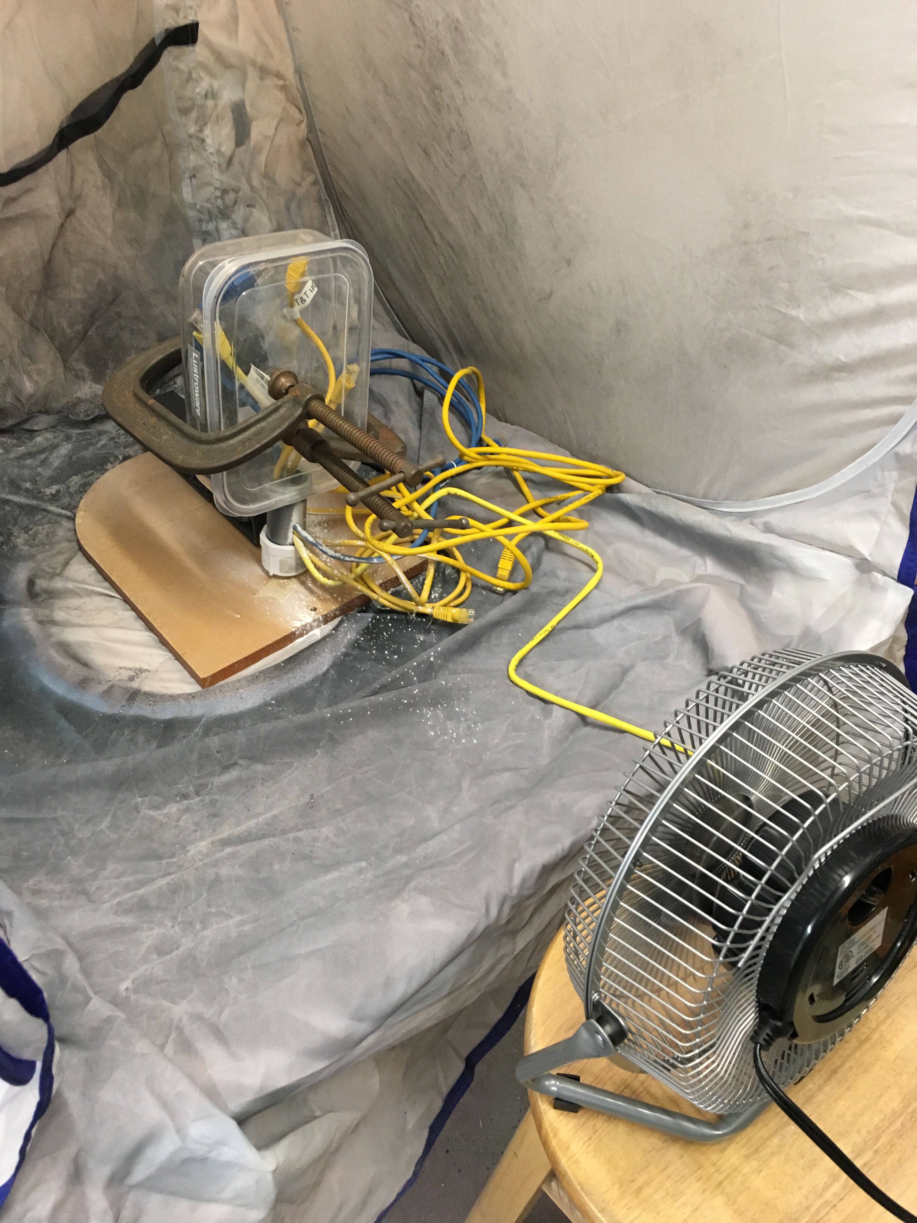
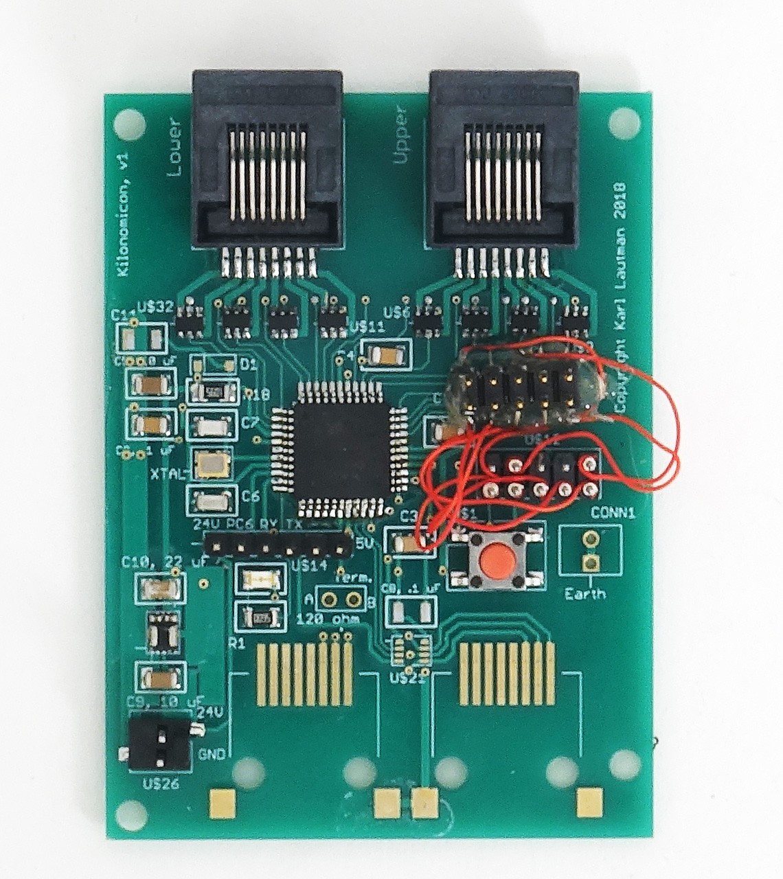
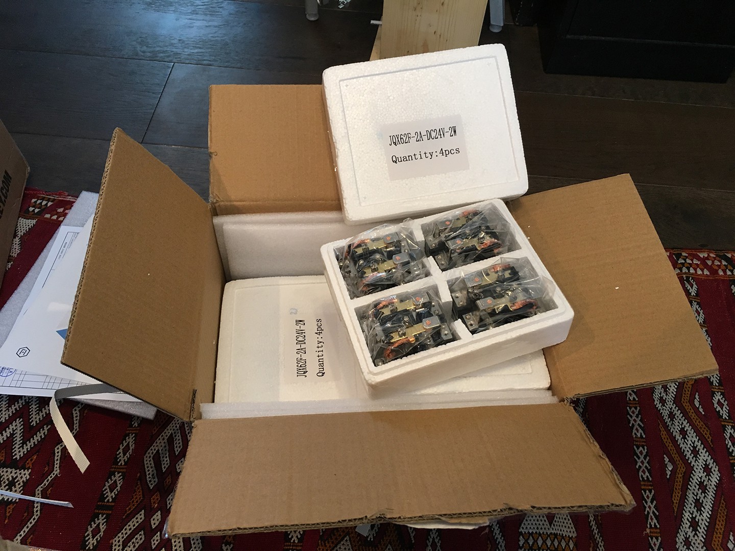
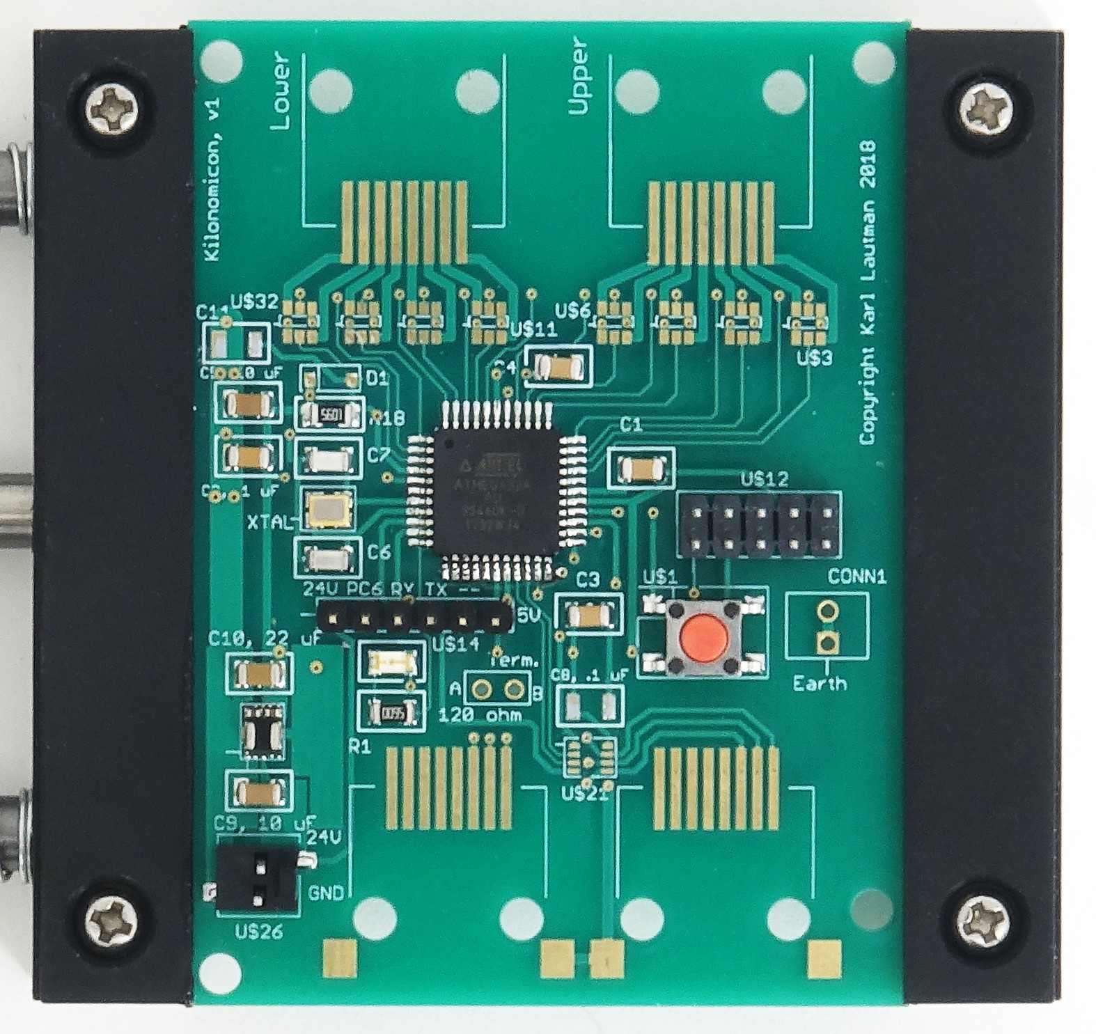
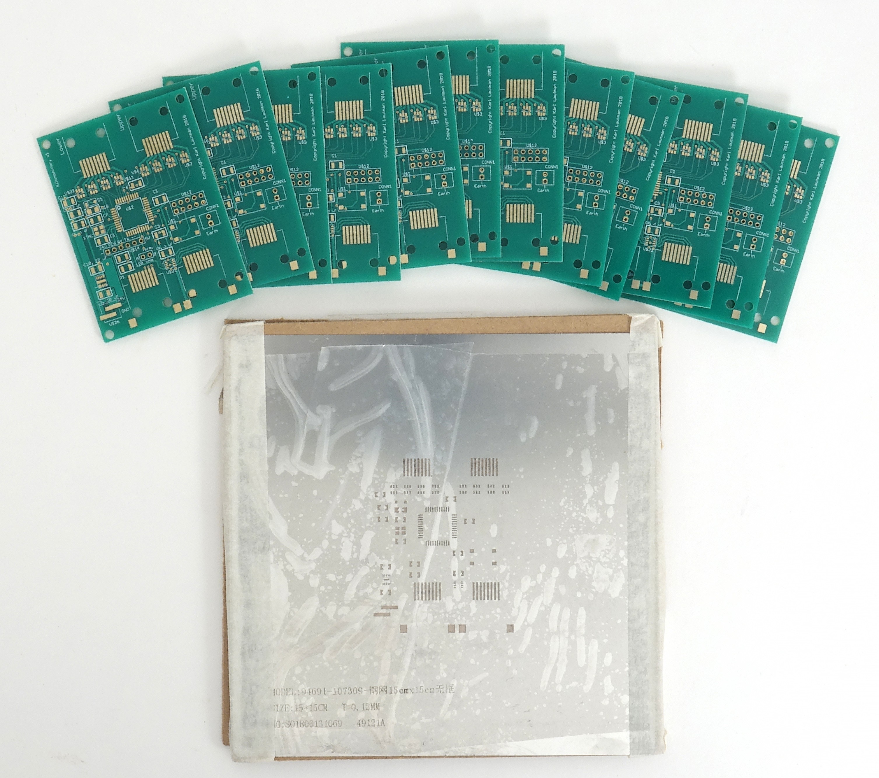
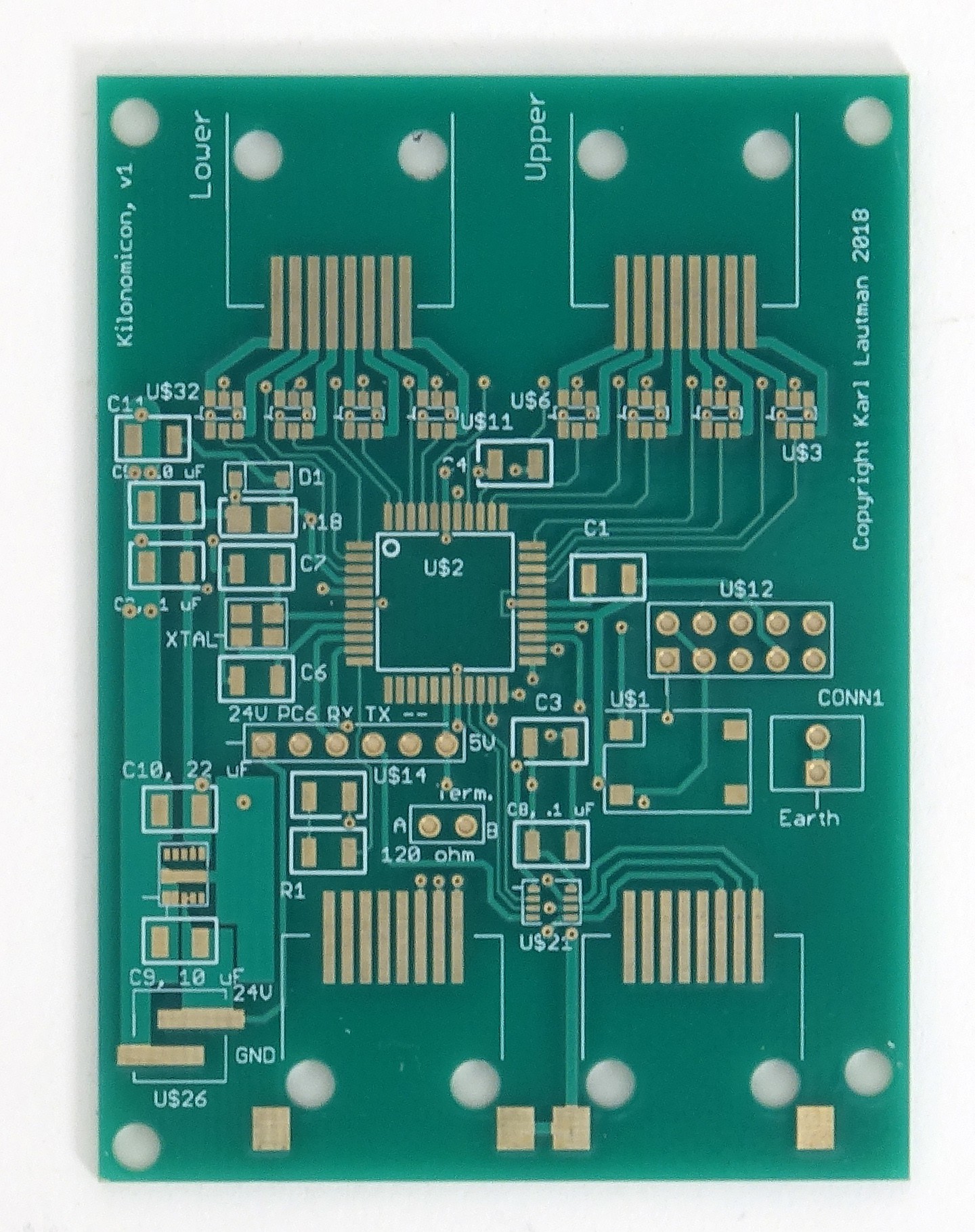
I'm on version 2 of the PCB design for the module controller which I'm about to release to the fab in China. I've evaluated several Chinese relay suppliers and settled on one; I've build one module out of 16 of their relays..
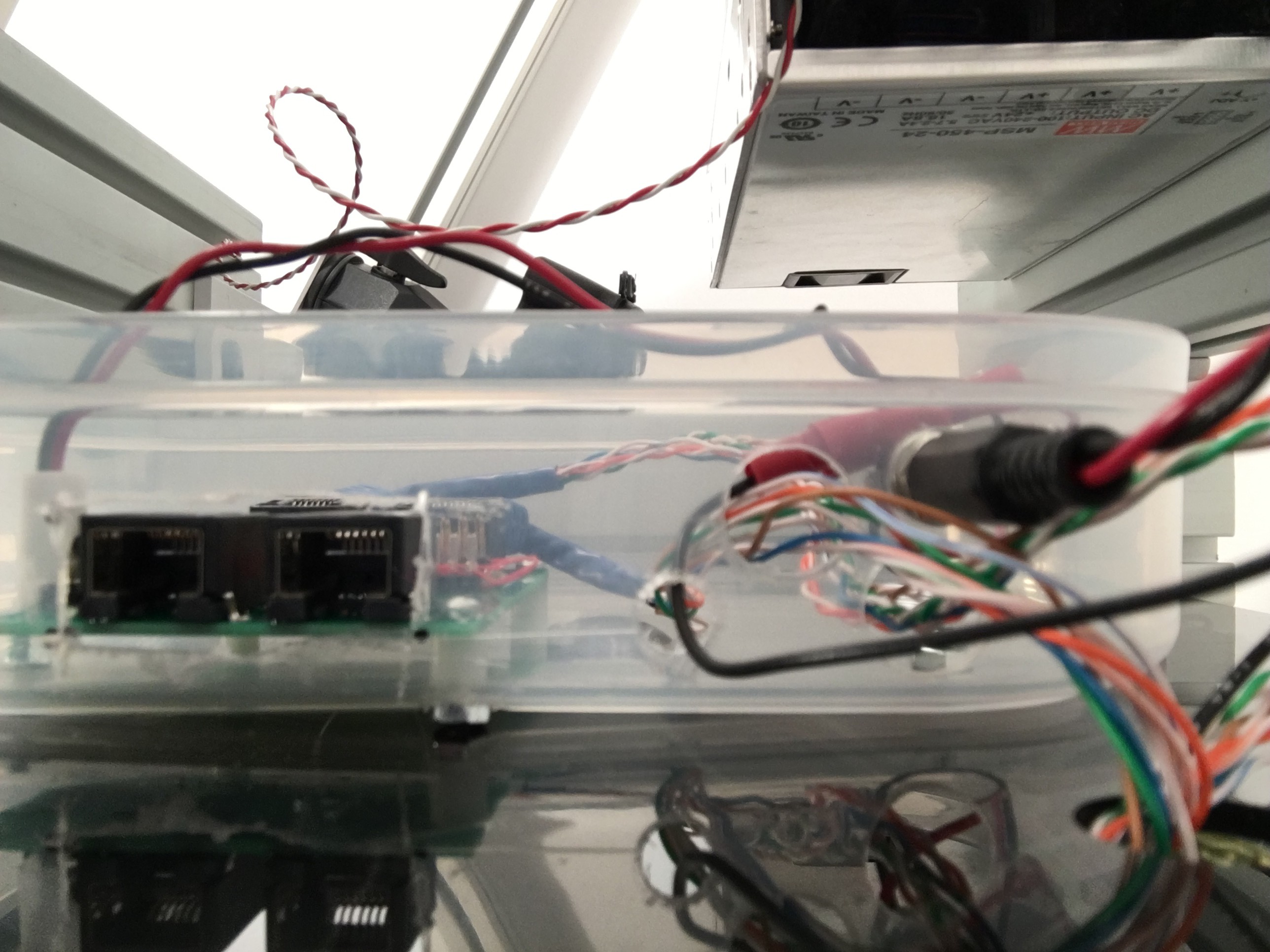
The relay control signals will be fed from the module controller via two RJ45 cables (each containing eight conductors). Due to their massive use everywhere, these are cheap, reliable, easy to find, and available in a wide variety of lengths and colors. Since they already have connectors on the ends, I won't have to make my own cables. In fact, I can take a single, say, 2' cable, cut it in half, and have the two cables I need for one module. All I have to do is strip the ends of the exposed wires. The RS485 network will also run over RJ45 cables (though these will be shielded).
My plan is to build a single module and use one of the module control boards to control it and another to...
Read more »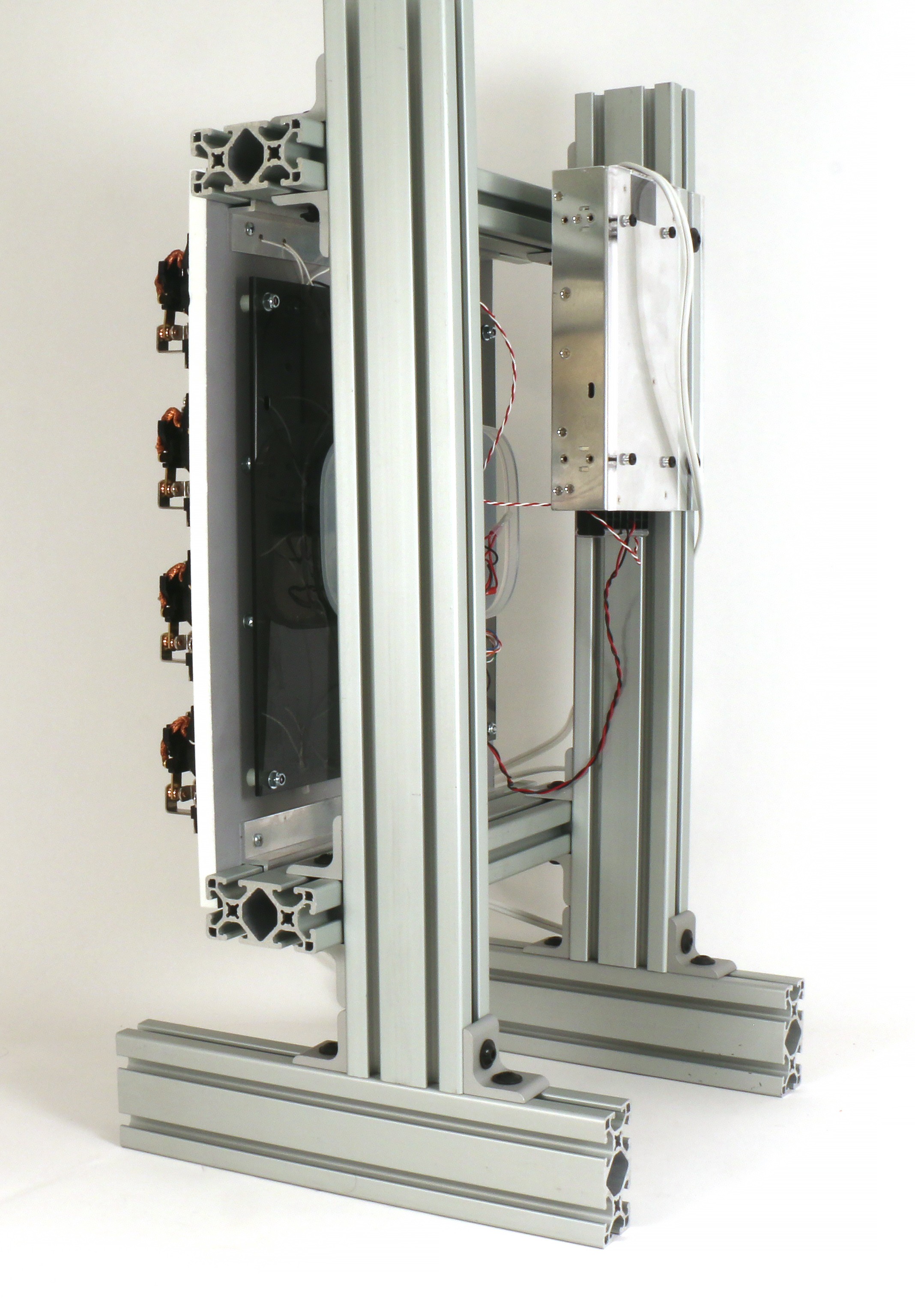

 Marek
Marek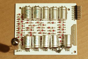
 Yann Guidon / YGDES
 Marsupilami
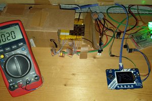
 Stefan Krüger
Music played by a 1000-piece mechanical relay orchestra? Sign me up!