Pondering what it means to build a discrete transistor ECL machine, it occurred to me to simulate a ring oscillator in LTspice, using the ON Semi model for the MPSH10 RF transistors since I have a stash of those. My simulation is based on the 1980's vintage Motorola 10H-series. The simulation suggested the oscillator would run around 230MHz, indicative of a propagation delay of ~725pS. This evening I figured, why not try building it? On a Proto-Board?
A couple hours of work, and I had a running ECL ring oscillator. Because my oscilloscope is not fast enough, I estimated the frequency using SpectrumSpy/Airspy - the oscillator is a bit noisy and proximity sensitive, but seems to be running at ~312MHz (when not spuriously oscillating like 12 RF transistors in a high-gain circuit are prone to do). This is indicative of a propagation delay of ~533pS. There are much better choices for high-speed transistors; modern state-of-the-art parts in a proper layout would likely see propagation below 200pS.
Current is ~2.3mA in each pair. Decent decoupling on all the Vcs nodes really helps on the Proto-Board :-)
For comparison, a ring oscillator built using a 74AHC04 on the same protoboard runs ~96MHz, ~1.7nS propagation delay (and is a lot easier to build :-)).
So here's the proto-board version; I did not really expect it to work well given parasitic capacitance and inductance, but with enthusiastic decoupling, it works pretty well. Note that the capacitance spread between rows and the baseplate probably serves as effective UHF decoupling, enhancing the circuit stability.
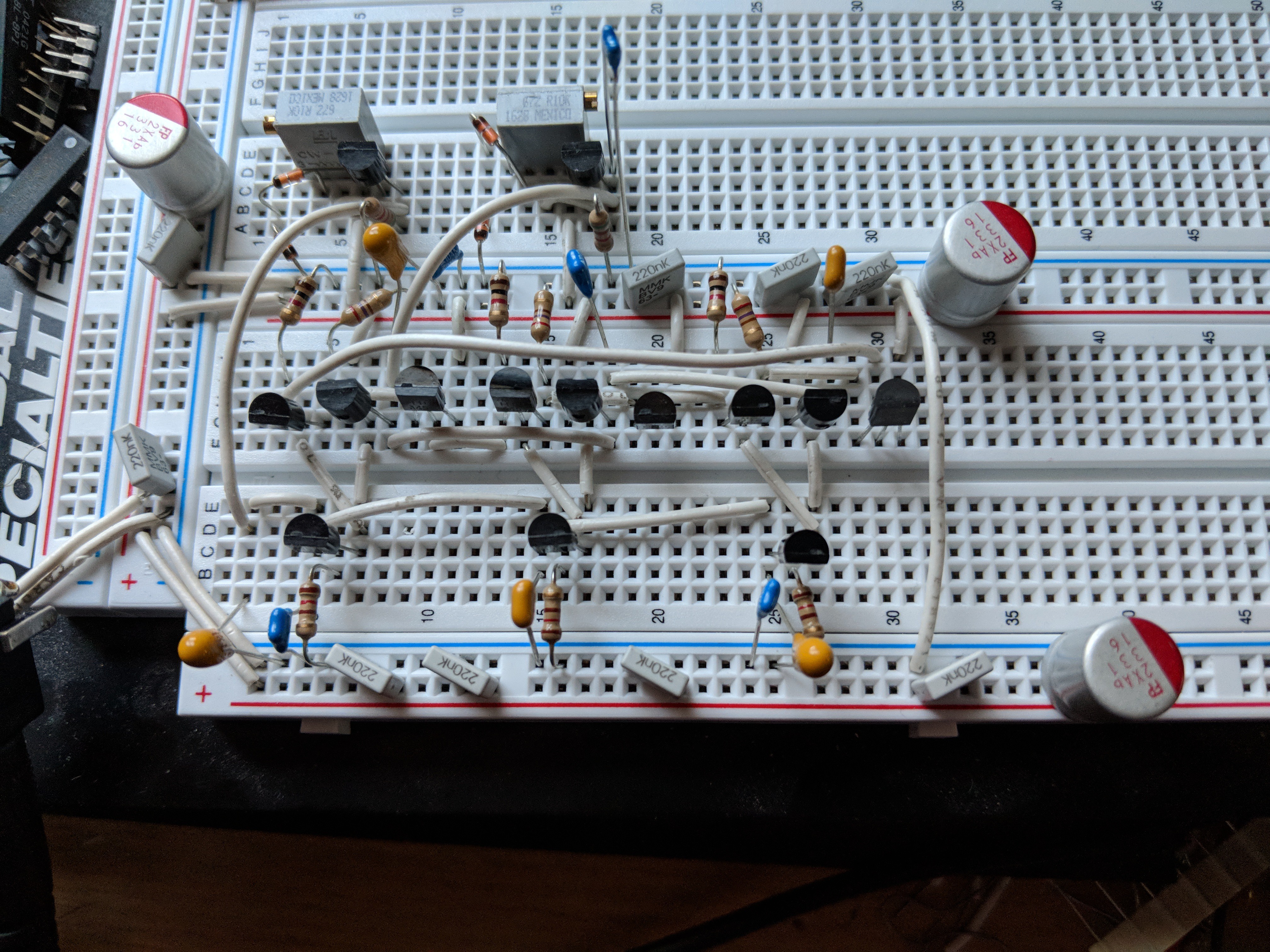
The bias circuitry for Vbb and Vcs is at top left; these are simple voltage dividers buffered with emitter-followers using relatively common MPS2222A transistors. In the vertical middle are the 3 ECL inverters consisting of a balanced-pair and output-buffer; directly below this are the 3 current-source transistors biased by Vcs.
Given the success building this, I tried building a better version on a piece of pad-per-hole groundplane.
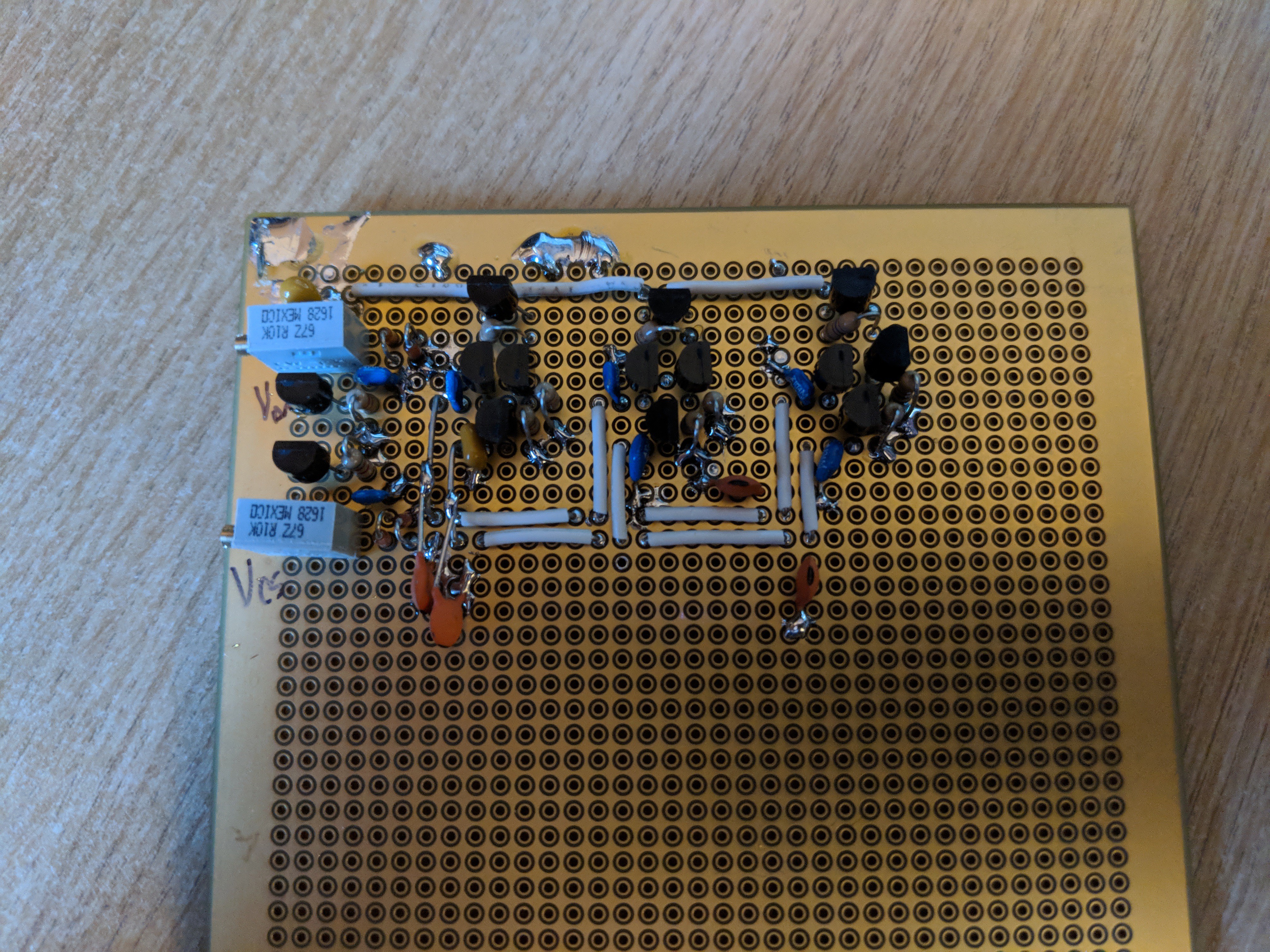
The same circuit, I thought I'd arranged it better; the Vbb and Vcs lines are at the bottom, and decoupled at each ECL inverter. However, it's not particularly stable; it seems to run around 550MHz, suggesting gate-delay of around 300pS, but stability is quite sensitive to Vcs bias setting. While I based this on the Motorola 10H-series design, I economized a bit and left out small-valued resistors in series with the inverter inputs, which are probably in the Motorola design to improve stability by reducing the 'Q' of parasitic reactances. I'll tinker with this circuit again.
This made me want to compare with the 'real deal - an actual Motorola 10H-series 10H189 hex inverter. After paying too much money on eBay for these obsolete parts, I built a very stable ring oscillator in just a few minutes.
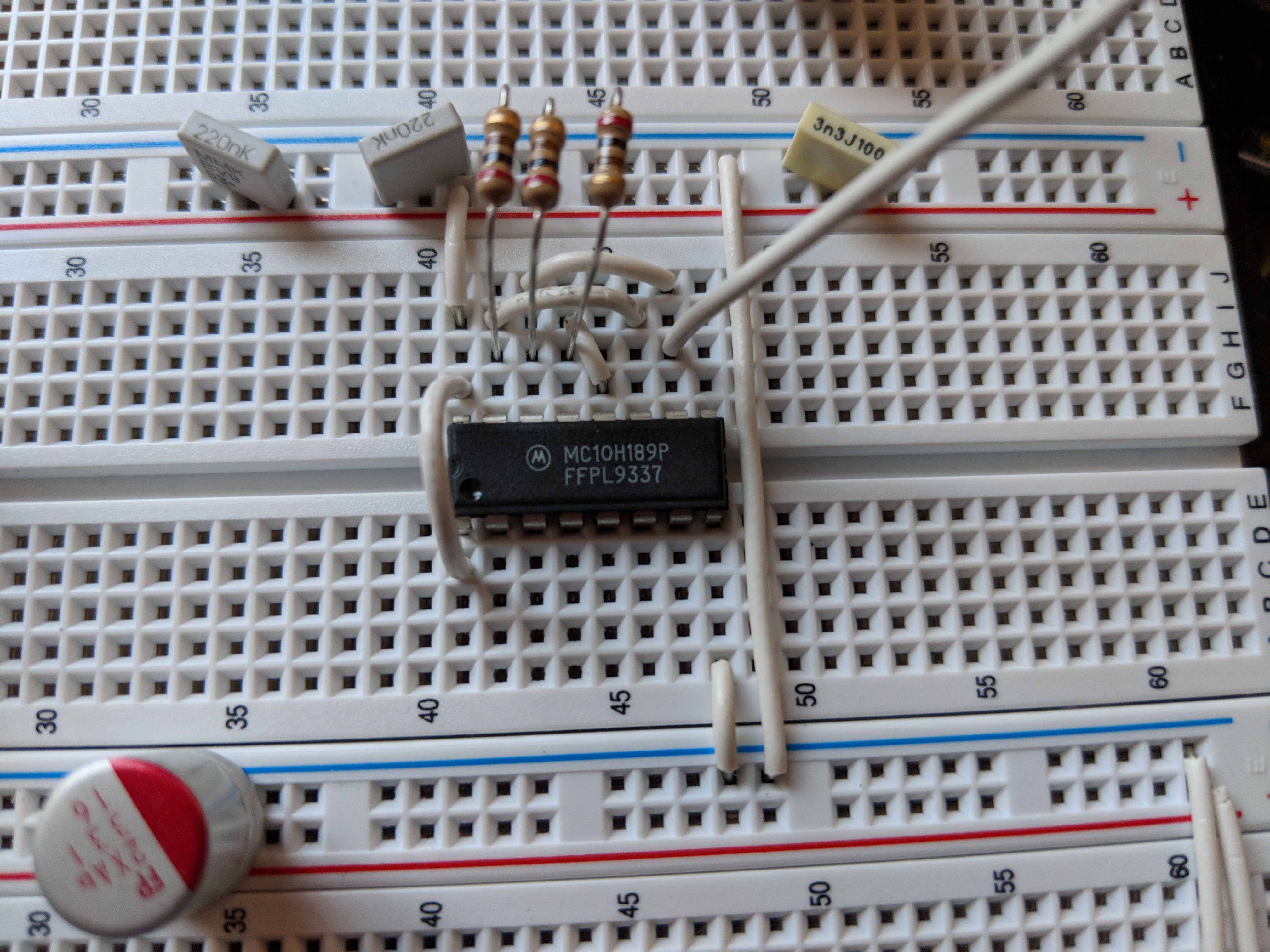
Using emitter-load resistors of 200 ohms to ground (rather than 50 ohms to Vcc - 2.0V, or 3.2V), this circuit is stable right around 181MHz, suggesting a per-gate propagation delay of ~920pS. Datasheet gives a typical value of 1.3nS with a standard load; I suspect this part is only slightly faster than that. Note the date code: that's 25 years ago!
 Yann Guidon / YGDES
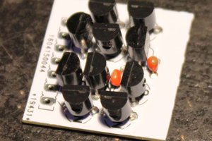
 Ted Yapo
 Tim
Tim
would you have some examples of "modern state-of-the-art parts in a proper layout" ?