 Curt White
Smart pills are already being used by doctors to save lives. Many more are being developed. There is an endoscope camera smart pill, a colon cancer detecting smart pill, an ulcerative colitis monitoring smart pill, a medication compliance smart pill, a targeted medication delivery smart pill, a microbiome monitoring smart pill, a battery removing origami robot smart pill, and quite a few more. Powering smart pills is difficult. High density batteries, especially lithium batteries, tend to be fairly toxic and only very small batteries will fit in a pill. It would be convenient if we could power devices by turning our GI tract into a battery. The common Alkaline battery uses sulfuric acid, along with zinc and manganese, to generate electricity. The concentration of hydrochloric acid (HCl) in stomach acid (gastric fluid) is about 0.16M and can be used to create a battery the same way sulfuric acid is used in alkaline batteries. The smart pill I'm building is about developing a technology that will make other smart pills more effective. My goal is to monitor the voltage and maximum current produced after it is swallowed and send data to an app over Bluetooth. As the project progresses, I have also started testing Magnesium-Copper galvanic cells.
(Above) Magnesium-copper (Mg-Cu) galvanic cell encased in the smart pill enclosure immersed in a 0.16M hydrochloric acid (HCL) solution. The voltage across the cell when fully immersed is 1.29V (average over one minute).
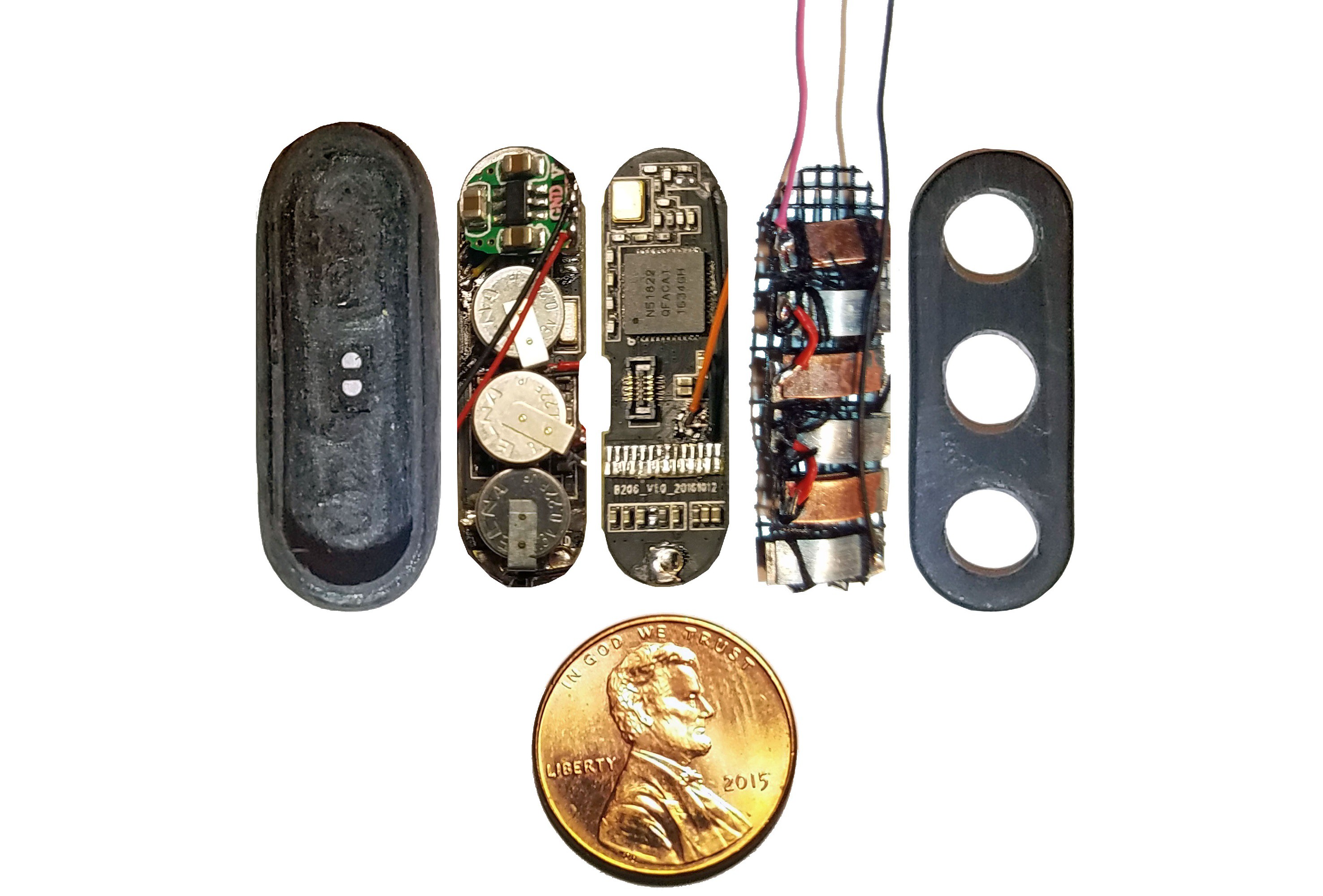
(Above) Components of smart pill sandwiched into injection molded plastic enclosure arrayed in ascending order left to right.
Far left: shaped and ground out activity tracker enclosure.
1st from left: three super capacitors in parallel, back charge protection diode, voltage boost converter, bottom view of activity tracker PCB.
2nd from left: top view of activity tracker PCB including Nordic nRF51822 ARM Cortex-M0 SoC chip.
3rd from left: pile of three Zn-Cu Galvanic cells in series. The electrodes have been sewn down to a plastic mesh to keep them in place and allow free flow of electrolyte.
Far right: enclosure cap with holes for gastric fluid containing hydrochloric acid electrolyte to enter device. The enclosure will be filled with epoxy until everything but the galvanic cells are encased so gastric fluid entering the enclosure will not damage the electronics.
DESIGN
Build Steps
- The OLED display, battery and vibration motor of a small hackable activity tracker are removed and the enclosure is shaped with a Dremel to make it more pill-shaped and create extra space.
- Three pairs of Zn-Cu strips as long as the activity tracker circuit board is wide are created. These Zn-Cu strip pairs are layed in an alternating array - the array is as wide as the activity tracker is long. The Zn-Cu pairs are wired so that they form three galvanic cells in series. I sew all these strips down to a of plastic mesh the same size as the activity tracker PCB to keep them in place. *Note: currently undecided as to whether Mg-Cu or Zn-Cu is best. Going back and forth for now.
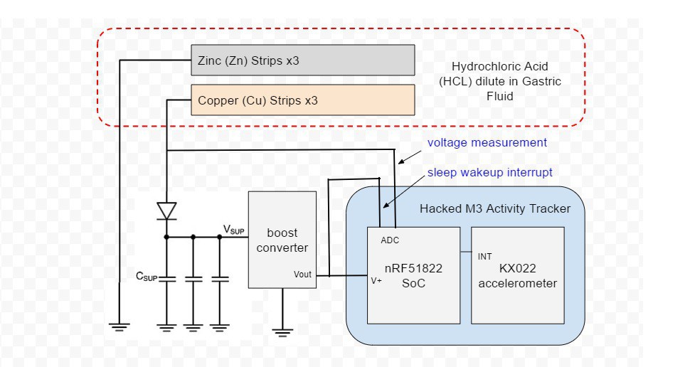
- The positive (copper) lead from the galvanic cell bank is connected to a Schottky diode and the negative (Magnesium) lead is connected to ground on the activity tracker PCB.
- Three tiny coin type 3.3v super capacitors are wired in parallel so that they form a capacitor bank. The positive leads from the capacitors are connected to the diode. The diode will prevent any back charge from the capacitors to the Zn-Cu strip galvanic cell which could cause side reactions. The negative leads are connected to ground on the activity tracker PCB.
- The super capacitor bank is connected to the input of a small 3v DC-DC boost converter. The output of the boost converter is connected to the voltage supply of the Nordic nRF51822 ARM Cortex-M0 MCU on the activity tracker. This will supply all other components on the activity tracker PCB as well.
- The galvanic cell bank will not provide enough power to keep the activity tracker on all the time. A GPIO pin on the MCU is configured as an ADC (Analog to Digital Converter), and connected to the positive lead of the super capacitor bank to monitor charge. This ADC is configured as an interrupt which will wake up the MCU from low power sleep when there is enough power to sample sensors and send data over the nRF51822's Bluetooth radio.
- Another MCU GPIO is configured as an ADC and connected to the positive lead of the Zn-Cu galvanic cell bank to monitor generated voltage. Readings will be sent over Bluetooth.
- If possible the activity tracker's KX022 accelerometer will be powered and sampled. This might require too much power. I may also sample the MCU's on board temperature sensor.
- Data from the smart pill is sent over BLE Bluetooth to a computer of smart phone periodically, probably every 8-12 seconds.
Stomach as Battery
In 1800 Alessandro Volta created the first true battery, the "voltaic pile". This consisted of zinc (anode) and copper (cathode) disks separated by saltwater (electrolyte) soaked cardboard. The zinc and copper underwent a chemical reaction called reduction-oxidation or simply "redox". Almost all batteries contain this combination of an anode, cathode and electrolyte.
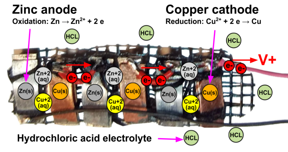
Above is a photo of the smart pills three galvanic cells in series. Placing multiple cells in series increases the output voltage. Electricity, or rather an electric potential, is generated by a chemical reaction. Zinc and copper have different electric potentials, in other words zinc (-0.76v standard potential) is naturally good at giving away electrons and copper (0.34v standard potential) is naturally good at receiving them. When zinc and copper are combined in an electrolyte as a galvanic cell, a reduction-oxidation reaction takes place. The zinc is literally reduced in size as solid zinc atoms give up their electrons to become dissolved in hydrochloric acid as zinc ions. The voltage supplied by a single Zn-Cu galvanic cell is approximately their total difference in electric potential: 0.34v - (-0.76v) = 1v , or more likely about 0.9v allowing for various inefficiencies.
The idea for this project originates in a research paper (in project files) from MIT that read a couple months ago: "Prolonged Energy Harvesting for Ingestible Devices" in Nature Biomedical Engineering. They built a stomach acid powered smart pill and tested it on pigs. Naturally I wanted to build my own version.
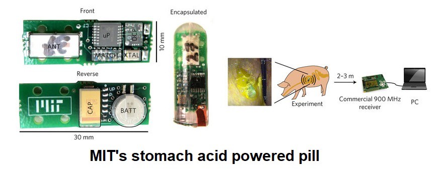
There are a variety of issues with MIT's smart pill that I try to address:
- Does it work on humans? MIT only tested on pigs. Pigs are a great animal model when you consider alternatives, but success in animal testing followed by failure in human trials is extremely common in pharmaceutical and medical device research. I intend to test this on myself, or at least my own gastric fluid. Ability to openly self test is a significant advantage hackers have over scientists.
- Enclosing the galvanic cell metal electrodes: MIT left the thin pointy metal electrodes dangle from their pill. I wouldn't swallow anything that looked like that, I want to enclose my device's electrodes where they can't poke holes through my stomach.
- No dangerous Lithium batteries (especially coin cell): little kids often accidentally eat coin Lithium batteries. The results are horrific. Encasing lithium batteries in epoxy so that they can't expand if they heat up exacerbates the issue. I replace the Lithium battery MIT uses in their pill with a bank of tiny super capacitors.
- Get it working with a BLE Bluetooth radio so I can connect to an app on my smartphone or computer.
- Program it using the Arduino IDE: if possible, I am going to write firmware using Sandeep Mistry's Arduino Core for Nordic nRF5x SoCs.
- Build it open source and make it cost less that $50 total.
Hardware
Using a M3 Nordic nRF51822 ARM Cortex SoC based hacked activity tracker as a foundation has significant advantages but also significant disadvantages. On the plus side I get a $25 device with lots of sensors that I can swallow whole without modification. If I were to encase the innards of the M3 with Epoxy without a plastic enclosure the way MIT does with their device it would be even easier to swallow. However, the Nordic nRF5x series isn't particularly great for this application. It doesn't have much in the way of power management in general, but the current it draws at startup is particularly problematic. In addition, the activity tracker has peripherals like a vibration motor, HR sensor, OLED display and capacitive touch button that are potential power leaks even after I remove what I can. So it will be a challenge. The device is designed to operate at 3-3.3v so that is what I will need to provide it.
Software
This project is an opportunity to play around with power management on Nordic nRF5x SoCs and hopefully apply what I learn to all my other nRF5x based projects. I will get the ball rolling with Nordic's ultra low power "Solar Powered Beacon Example" which they also provide on GitHub. The big question is whether I can get away with using Arduino like I did on my other activity tracker Hackaday projects. Using Arduino means no RTC (Real Time Clock). The most important data the smart pill needs to gather is information about how much electricity it generates - this smart pill is about developing a technology that will make other smart pills more effective. Measing voltage generated by the galvanic cell is easy, all I have to do is connect the galvanic cell positive lead to an ADC on the activity tracker MCU. Maximum available current is more difficult. I'm measuring current by making power availability control when the device exits low power sleep mode to transmit data over Bluetooth. If I know how much current the device consumes and allow it to consume as much power as it can I can calculate current based on when it wakes up and goes back to sleep. All I have to do is connect an ADC to the super capacitors and set it as an interrupt.
Testing
The MIT researchers who inspired this project tested their device by creating synthetic/simulated gastric fluid and testing their device on a pig. Pigs are good animal models for testing devices intended for human use but MANY drugs and devices have succeeded for pigs, mice or monkeys only to fail during human testing. I want to know if this will work on humans, which means self testing. First, testing on regurgitated gastric fluid - then I intend to actually swallow this pill I'm building.
It isn't as crazy as it sounds, people swallow and pass all kinds of weird stuff without a problem.
Hacking Activity Trackers
This project is a spin-off of my "Hacking Wearables for Mental Health and More" project which presents hacked activity trackers as a platform for developing wearable devices. I'm trying to demonstrate a variety of ways the platform can be used. The tiny M3 activity tracker used in this project is also used in another spin-off project, "Intraoral Respiration Monitor & Overdose Detector". These projects along with "Hacking a $25 nRF51 ARM Cortex Activity Tracker" provide all the information needed to hack the M3 activity tracker.