 Al Williams
Combinatorial design is easy to understand with AND, OR, and NOT gates doing most of the work. These designs are great for things where the previous state of the system doesn't matter. For example, imagine a car with an interior dome light. You want the light to come on if any of the doors are open (D1-D4) or the dashboard switch for interior light is on (S1). You can express that with an OR gate (or the | sign which is typically used for OR) Z=D1|D2|D3|D4|S1. Or perhaps you want all those conditions but only if a sensor says it is dark (X1). Then you could do an AND (&): Z=X1&(D1|D2|D3|D4|S1).
However, consider the car's alarm. It might also look at D1, D2, D3, and D4. But what it does will depend on if the system is armed or not. Let's take the simplest case. The system should arm if it gets a pulse from the keyfob receiver K1. Another pulse will disarm it. While the system is armed, any input from D1, D2, D3, or D4 should set off the alarm. There's a problem with this, but let's look at it first before we work on the problem.
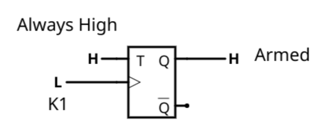
The arming/disarming can be done with a T flip flop. This is the kind of flip flop that toggles its output with each clock pulse. So for example, if you forced the T input high you could connect K1 to the clock and the Q output would tell you if the system is armed or not (try it on Falstad).
Now it would be simple to use a 4 input OR gate and an AND gate

That works (try it on Falstad).
However, there is a slight problem. When you open a door and the system is armed, the alarm goes off as it should, but once you close the door, the alarm goes off again. Not ideal.
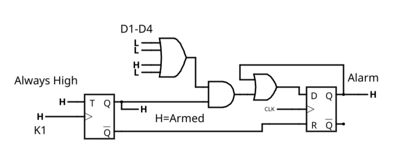
To fix that you need another flip flop that remembers the alarm is on until the alarm is disarmed. You can try that on Falstad too:

This is a bit odd because of the way it is clocked. In this case, the K1 signal is the clock for the T flip flop. The D flip flop uses a little delay (two inverters) to ensure the D line is stable by the time the clock edge rises. The R pin on the D flip flop is a reset and any time the system is not armed, it forces the output of the D flip flop to be low.
In most FPGA systems, you will have one (or sometimes a few) master clocks. For example, consider this circuit:
This is essentially the same as the last circuit, but the D flip flop now has a clock that runs all the time. If a door managed to open and close faster than the clock period, the alarm would not trigger! Of course, if the clock were, say, 10 MHz, there would not be much chance of that really happening. The OR gate in front of the D flip flop makes it "stick" on. That is, once Q goes high, it will stay high until the reset forcibly turns it off.
So what do flip flops do for you?
1) They give your circuit memory, like in the above example.
2) They provide a fixed time for inputs to stabilize before producing an output. This is discussed more in the main portion of the tutorial.
Flip flop "memory" allows you to create things like counters, registers, and state machines -- topics for future bootcamps.
Discussions
Become a Hackaday.io Member
Create an account to leave a comment. Already have an account? Log In.