Close
0%
0%

Flexible wearable power harvester

A miniature power harvester solar-based for wearables, IoT and my smart ring series

Public Chat
Similar projects worth following
As the technology advances, the electric components diminishes, making room for new tiny inventions. One of the field which has seen more beneift is the wearable technology which limiting factor seems to be the powering, so I want to make an small ambient light micro power energy harvesting module which fits even in a ring.

The project would be powered by small photodiodes, driven by a power harvesting ic. All the power is stored on a supercapacitor, with an additional storage batteries if required, for more power demanding applications. The module has a power output regulated by a buck converter, fixed at 3.3V (enough voltage for run most of applications).

I'm also making an smart ring-series, and I'm looking to fit this project in all my rings, for that reason, the energy harvester would have the smallest footprint possible. Due to homemade manufacturing limitation of flex PCBs, I can't make vias, so it will be one side pcb.

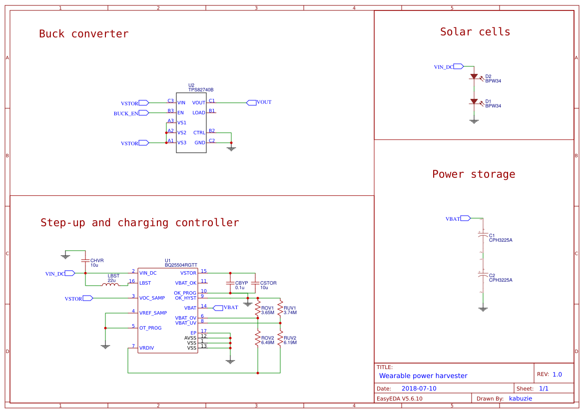
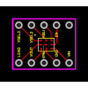
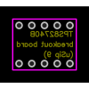
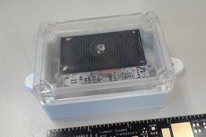
The main components of this project are the tiny BPW34 solar cells, which provides about 300mV. With two in series we can reach the start up cold unit of the power harvester ic BQ25504, and adding more solar cells in parallel helps to reach the minimum start up power (15uW) sooner. This ic regulates the charge of two CPH3225A (0.011F supercapacitor) in series, with a max voltage of 5.25V (limited by the ic max voltage specification). The external buck converter TPS82740B allows discharging it securely (there are programmable overvoltage and undervoltage conditions setted by resistors into the harvester IC) which would discharge the caps from 5.25V to 3.3V.

In ideal conditions, two CPH3255A provides a power storage of 12.74uWh (45.85mJ), which means 3.86uAh at 3.3V. The CPH3225A have an internal resistance of 160ohms, so the module would provide a max of 10mA, which is enough for the most of low power applications. 

I chose the CPH3225A for its 0.9mm height, but there are better alternatives which I'm looking, for example the DCK-3R3E204T614-E, which have an 1.4mm height and 200mF, which would provide 834mJ or 231uWh (0.07mAh).

I have not taken into account the inefficiency of the buck converter, which is worse with small currents, so a bit of testing should be made here. In theory an efficiency of 90% is possible at 10uA, but lowering to 1uA will reduce the efficiency to 60%.

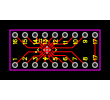
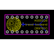
All should fit in a small flex pcb one sided, so I would need some 0ohm resistor for make bridges.

x-zip-compressed - 6.33 kB - 07/15/2018 at 13:51

Download

Gerber_BQ25504_breakout_20180703160753.zip

Breakout board of BQ25504 (Gerber files)

x-zip-compressed - 89.91 kB - 07/03/2018 at 14:10

Download

  • 2 × BPW34 Miniature solar cell - photodiode
  • 1 × BQ25504 Evaluation, Demonstration Kits, Boards and Modules / Evaluation Kits, Boards and Modules
  • 1 × SRN3012TA-220M Smd inductor
  • 2 × CPH3225A Super capacitor
  • 1 × TPS82740B Buck module

  • Proof of concept renders

    Enrique07/14/2018 at 16:24 0 comments

    One of the main aspects of wearables is the aesthetics. I wanted to know how well the power harvesting module would fit in one of the rings which I have in mind, so I 3d designed all the components respecting the measures. Here are the renders:

    The power harvesting module is in the yellow flex board, with the two solar cells on the left and four supercapacitors on the right. The rest of components are 3 RGB leds and a microcontroller with some more circuits that I will explain in to my smart ring project page.

    Here is with a plastic shell, three diffusers for the LEDs and two holes for the solar cells.

  • Making the first schematic

    Enrique07/10/2018 at 20:50 0 comments

    I have sketched a quick schematic about the general idea, but needs be polished and tested so shouldn't be taken as the final one.

    There are some details:

    -The CBYP should be a low leakage

    -The CBYP should be placed close to VSTOR and GND

    -The CSTOR should have a low ESR, and it's value is related to the cold start efficiency and time

    -Is possible to add more solar cells on parallel or in series, but I prefer on parallel for not exceed the max input voltage.

    -The inductor should have similar specs to one of the given in the datasheet

  • Choosing the right resistors

    Enrique07/09/2018 at 22:39 0 comments

    The BQ25504 have the ability to provide undervoltage and overvoltage charging regulation, which ensures that the storage component doesn't get damaged. For programming this threshold certain resistor values are required. There's a formula on the datasheet, but Texas Instruments have a spreadsheet which calculates it.

    The sum of the resistor divider should be equal to 10Mohms and the undervoltage calculation is the next following;

    VBAT_UV = 1.25V(VBIAS) * (1 + RUV2/RUV1)

    so, with RUV1 = 3.74MOhm and RUV2 = 6.19MOh, we get: 3.32V

    The overvoltage calculation is the next following;

    VBAT_OV = 3/2 * 1.25V(VBIAS) * (1 + ROV2/ROV1)

    so, with ROV1 = 3.65MOhm and ROV2 = 6.49MOh, we get: 5.21V

    We have to take into account too the hysteresis values, which are:

    VBAT_UV_HYST = 80mV

    VBAT_OV_HYST = 35mV

    The IC also provides two more resistor dividers, the VBAT_OK, which turn on a flag when the battery voltage is on certain threshold and the MPPT. I'm going to try to avoid using both, for having more space and making the pcb traces simpler. The battery voltage can be monitored with an external uC, so the VBAT_OK flag is not required. The MPPT provides a more optimal energy harvesting, but for testing purposes I'm going to disable it, and if I see that makes a different, try to implement it.

  • Designing a few breakout boards

    Enrique07/03/2018 at 22:21 0 comments

    Before messing up soldering into a custom pcb, I want to test the BQ25504 with discrete components, and in a more debuggable way (is a relatively expensive IC for a student), for that reason I have sketched a couple of breakout boards and ordered it to OSHPARK

    I have also made another for the TPS82740B, which is packed in a solder ball package

    BQ25504:

    Front PCB:

    Back PCB:

    I added the thermal pad as an extra pin, for testing purposes.

    TPS82740B:

    Front PCB:

    Back PCB:

    Both breakout boards are in the download section

View all 4 project logs

Enjoy this project?

Share

Discussions

Similar Projects

Does this project spark your interest?

Become a member to follow this project and never miss any updates