 RoboCircuits
COMPONENTS AND SUPPLIES
 |
| × | 1 | |||
 |
| × | 1 | |||
 |
| × | 1 |
APPS AND ONLINE SERVICES
 |
|
ABOUT THIS PROJECT
Line Follower Robot
Best & Fast PCB Supplier (2$ for 10 PCBs) https://jlcpcb.com
YouTube
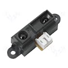
A proximity sensor is a sensor able to detect the presence of nearby objects without any physical contact. A proximity sensor often emits an electromagnetic field or a beam of electromagnetic radiation (infrared, for instance), and looks for changes in the field or return signal.
Concepts of Line Follower
Concept of working of line follower is related to light. We use here the behavior of light at black and white surface. When light fall on a white surface it is almost full reflected and in case of black surface light is completely absorbed. This behavior of light is used in building a line follower robot.


In this arduino based line follower robot we have used IR Transmitters and IR receivers also called photo diodes. They are used for sending and receiving light. IR transmits infrared lights. When infrared rays falls on white surface, it’s reflected back and catched by photodiodes which generates some voltage changes. When IR light falls on a black surface, light is absorb by the black surface and no rays are reflected back, thus photo diode does not receive any light or rays.
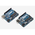
Here in this arduino line follower robot when sensor senses white surface then arduino gets 1 as input and when senses black line arduino gets 0 as input.
Circuit Explanation
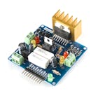
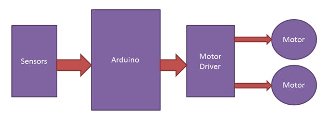
The whole arduino line follower robot can be divided into 3 sections: sensor section, control section and driver section.
Sensor section:
This section contains IR diodes, potentiometer, Comparator (Op-Amp) and LED’s. Potentiometer is used for setting reference voltage at comparator’s one terminal and IR sensors are used to sense the line and provide a change in voltage at comparator’s second terminal. Then comparator compares both voltages and generates a digital signal at output. Here in this line follower circuit we have used two comparator for two sensors. LM 358 is used as comparator. LM358 has inbuilt two low noise Op-amps.
Working of Line Follower Robot using Arduino
Working of line follower is very interesting. Line follower robot senses black line by using sensor and then sends the signal to arduino. Then arduino drives the motor according to sensors’ output.
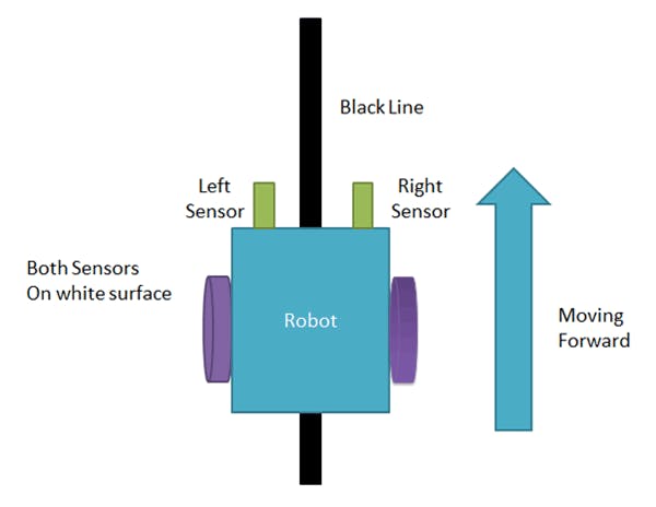
Here in this project we are using two IR sensor modules namely left sensor and right sensor. When both left and right sensor senses white then robot move forward.
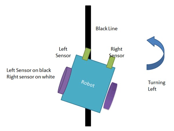
If left sensor comes on black line then robot turn left side.
If right sensor sense black line then robot turn right side until both sensor comes at white surface. When white surface comes robot starts moving on forward again.

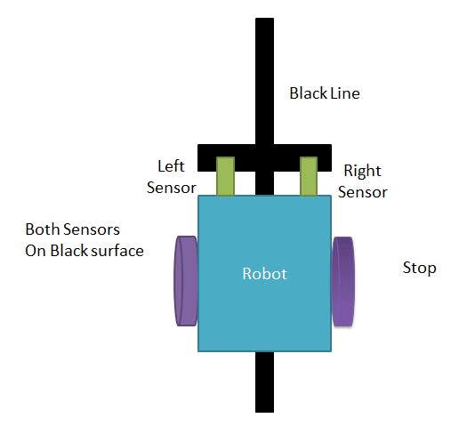
If both sensors comes on black line, robot stops.
*******BUY*******
Arduino UNO – https://www.gearbest.com/arduino-scm-supplies/pp_311407.html?wid=1433363&lkid=14127045
Full Arduino Project Kit – https://www.gearbest.com/development-boards/pp_211518.html?wid=1433363&lkid=14127055
Music – https://bensound.com – Summer
Website – https://robocircuits.com
Facebook – https://facebook.com/Robocircuits
Instagram – https://Instagram.com/Robocircuits
Twitter – https://Twitter.com/Robocircuits
CODE
CodeC/C++
| 1 2 3 4 5 6 7 8 9 10 11 12 13 14 15 16 17 18 19 20 21 22 23 24 25 26 27 28 29 30 31 32 33 34 35 36 37 38 39 40 41 42 43 44 45 46 47 48 49 50 51 52 53 54 55 56 57 58 59 60 61 62 63 64 65 66 67 68 69 70 71 72 73 74 75 76 77 78 79 80 81 82 83 84 85 86 87 88 89 90 91 92 93 94 95 96 97 98 99 100 101 102 103 104 105 106 107 108 109 | <span id="line-1"> <span class="kt">int</span> <span class="n">vSpeed</span> <span class="o">=</span> <span class="mi">110</span><span class="p">;</span> <span class="c1">// MAX 255</span>
</span><span id="line-2"> <span class="kt">int</span> <span class="n">turn_speed</span> <span class="o">=</span> <span class="mi">230</span><span class="p">;</span> <span class="c1">// MAX 255 </span>
</span><span id="line-3"> <span class="kt">int</span> <span class="n">turn_delay</span> <span class="o">=</span> <span class="mi">10</span><span class="p">;</span>
</span><span id="line-4">
</span><span id="line-5"><span class="c1">//L293 Connection </span>
</span><span id="line-6"> <span class="k">const</span> <span class="kt">int</span> <span class="n">motorA1</span> <span class="o">=</span> <span class="mi">8</span><span class="p">;</span>
</span><span id="line-7"> <span class="k">const</span> <span class="kt">int</span> <span class="n">motorA2</span> <span class="o">=</span> <span class="mi">10</span><span class="p">;</span>
</span><span id="line-8"> <span class="k">const</span> <span class="kt">int</span> <span class="n">motorAspeed</span> <span class="o">=</span> <span class="mi">9</span><span class="p">;</span>
</span><span id="line-9"> <span class="k">const</span> <span class="kt">int</span> <span class="n">motorB1</span> <span class="o">=</span> <span class="mi">12</span><span class="p">;</span>
</span><span id="line-10"> <span class="k">const</span> <span class="kt">int</span> <span class="n">motorB2</span> <span class="o">=</span> <span class="mi">13</span><span class="p">;</span>
</span><span id="line-11"> <span class="k">const</span> <span class="kt">int</span> <span class="n">motorBspeed</span> <span class="o">=</span> <span class="mi">11</span><span class="p">;</span>
</span><span id="line-12">
</span><span id="line-13"><span class="c1">//Sensor Connection</span>
</span><span id="line-14"> <span class="k">const</span> <span class="kt">int</span> <span class="n">left_sensor_pin</span> <span class="o">=</span><span class="n">A0</span><span class="p">;</span>
</span><span id="line-15"> <span class="k">const</span> <span class="kt">int</span> <span class="n">right_sensor_pin</span> <span class="o">=</span><span class="n">A1</span><span class="p">;</span>
</span><span id="line-16">
</span><span id="line-17">
</span><span id="line-18">
</span><span id="line-19"> <span class="kt">int</span> <span class="n">left_sensor_state</span><span class="p">;</span>
</span><span id="line-20"> <span class="kt">int</span> <span class="n">right_sensor_state</span><span class="p">;</span>
</span><span id="line-21">
</span><span id="line-22"><span class="kt">void</span> <span class="nf">setup</span><span class="p">()</span> <span class="p">{</span>
</span><span id="line-23"> <span class="n">pinMode</span><span class="p">(</span><span class="n">motorA1</span><span class="p">,</span> <span class="n">OUTPUT</span><span class="p">);</span>
</span><span id="line-24"> <span class="n">pinMode</span><span class="p">(</span><span class="n">motorA2</span><span class="p">,</span> <span class="n">OUTPUT</span><span class="p">);</span>
</span><span id="line-25"> <span class="n">pinMode</span><span class="p">(</span><span class="n">motorB1</span><span class="p">,</span> <span class="n">OUTPUT</span><span class="p">);</span>
</span><span id="line-26"> <span class="n">pinMode</span><span class="p">(</span><span class="n">motorB2</span><span class="p">,</span> <span class="n">OUTPUT</span><span class="p">);</span>
</span><span id="line-27">
</span><span id="line-28"> <span class="n">Serial</span><span class="p">.</span><span class="n">begin</span><span class="p">(</span><span class="mi">9600</span><span class="p">);</span>
</span><span id="line-29">
</span><span id="line-30"> <span class="n">>span class="crayon-o"></span><span class="p">(</span><span class
|