 mmca
mmcaOn the earlier Blinky Ball with single color LEDs we just placed the holes near the edge and bent the LEDs over, it was easy and made for a very strong connection.
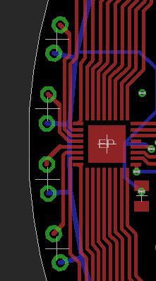
When we moved to an common cathode RGB LED with four legs it got a little trickier. It need to have four signals going to it, so I had this crazy notion of putting half the leads on one side of the PCB and the other two leads on the other side.
This worked pretty well, its very strong and the LEDs line up directly on the middle of the PCB edge. The main issue with this technique is that its a real pain to bend all the leads to fit on the PCB. Each LED had to have its leads formed, then clipped to length.
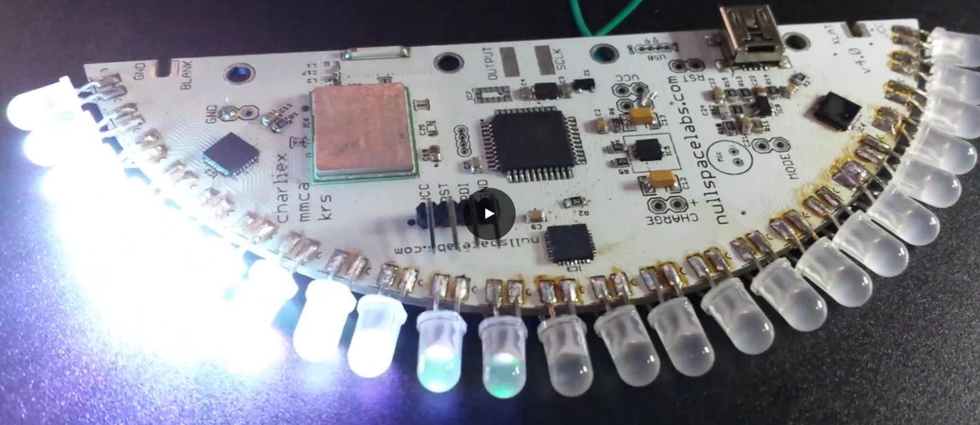
Next we moved to a WS2812 based addressable LED. It still has 4 leads, but they get daisy chained together. So in the current ball the PTH LEDs are just soldered in on their sides.
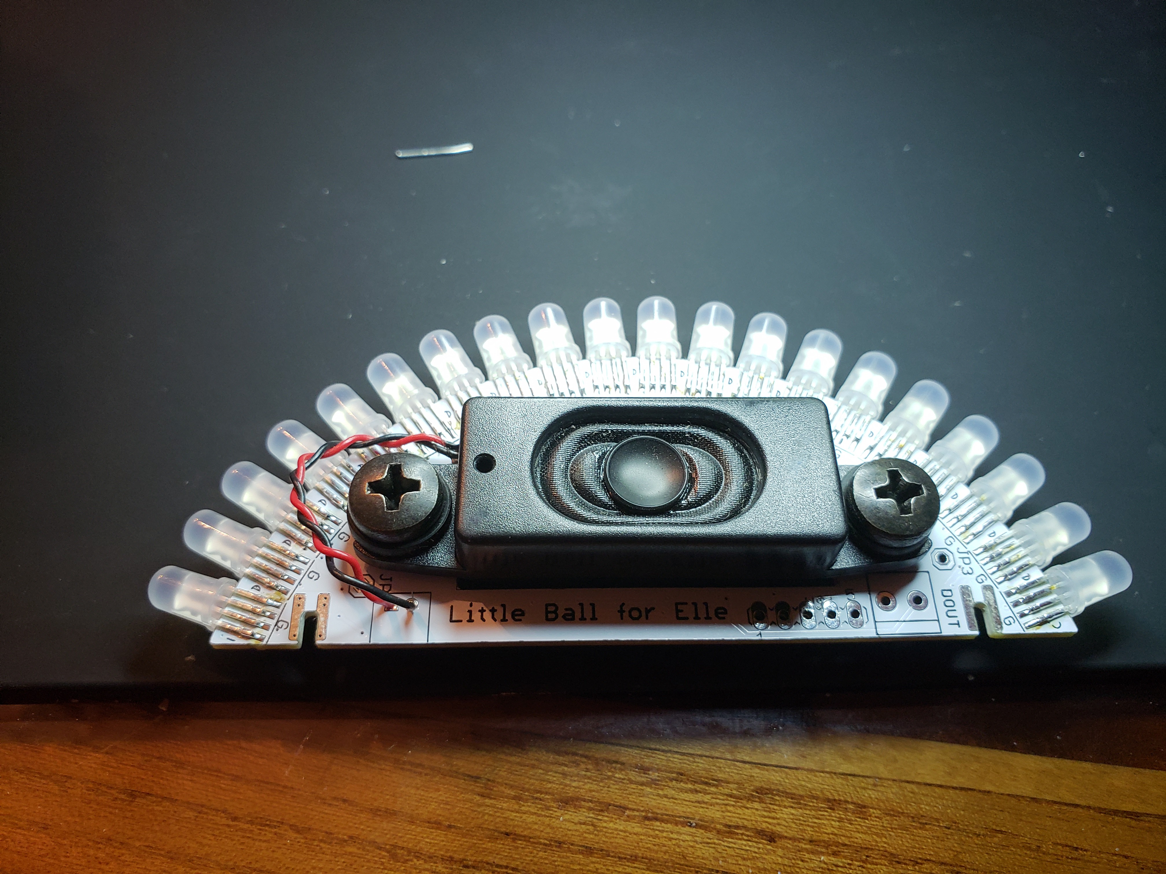
At first I thought this would be an issue as the LEDs aren't centered on the PCB edge, but you really cant tell. I also had concerns of the LEDs ripping off the pads, but it seems having 4 long pads is plenty strong. (Yes, that's a speaker... more on that later.)
Discussions
Become a Hackaday.io Member
Create an account to leave a comment. Already have an account? Log In.