 mmca
mmca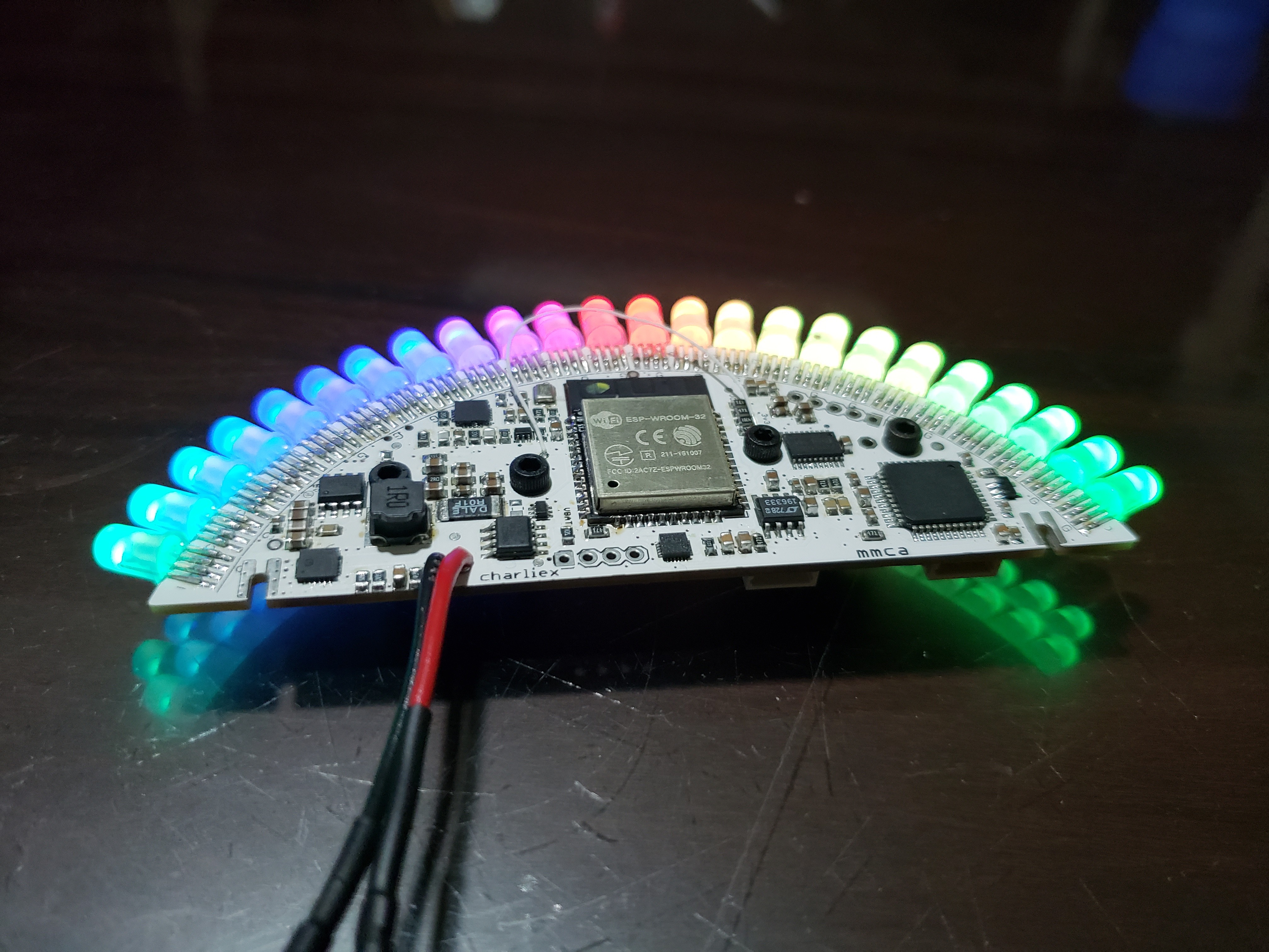
I like to build new boards by hand, one section at a time to make sure everything works like it is supposed to, in this case that did not help too much. Here are some of the fun mistakes I made on this board.
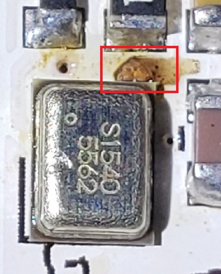
I forgot to change the isolation in the GND pour and ended up with very tight clearances. In this case 1.5A of 3v3 was right next to a small chip in the solder mask, a solder ball found it way to that gap it blew it out. If I had had allowed a little more isolation in the GND plane, that area would have been clear and the chip in the solder mask would not have had any affect. I fixed it with a little bit of nail polish, and this particular board is fine now.
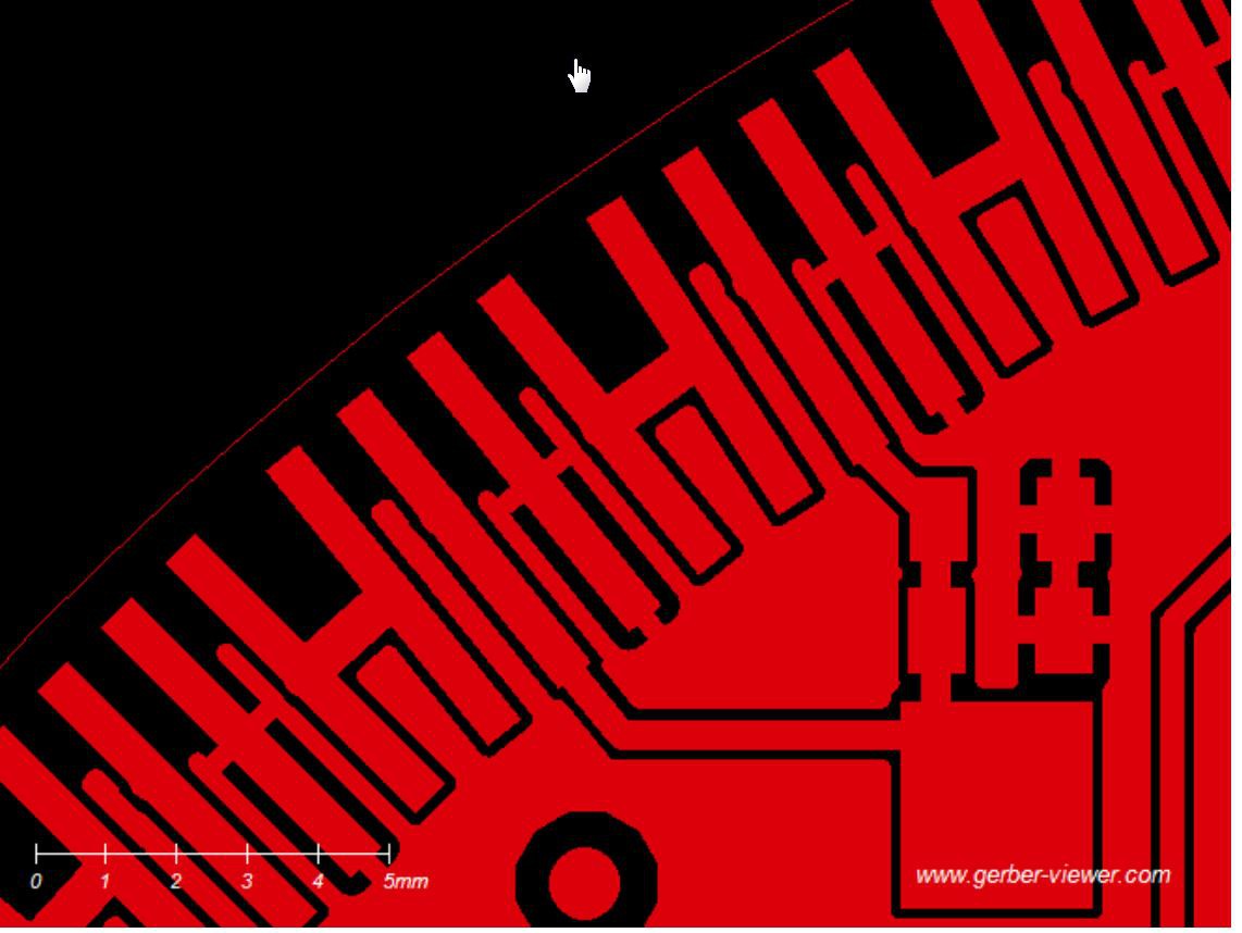
Here I isolated a little island of GND. I don't even have a copy of the board file with this error, so I must have fixed it in the general course of tidying up the board. Unfortunately it got sent to the board house, so the prototype has 15 little bits of Kynar wire.
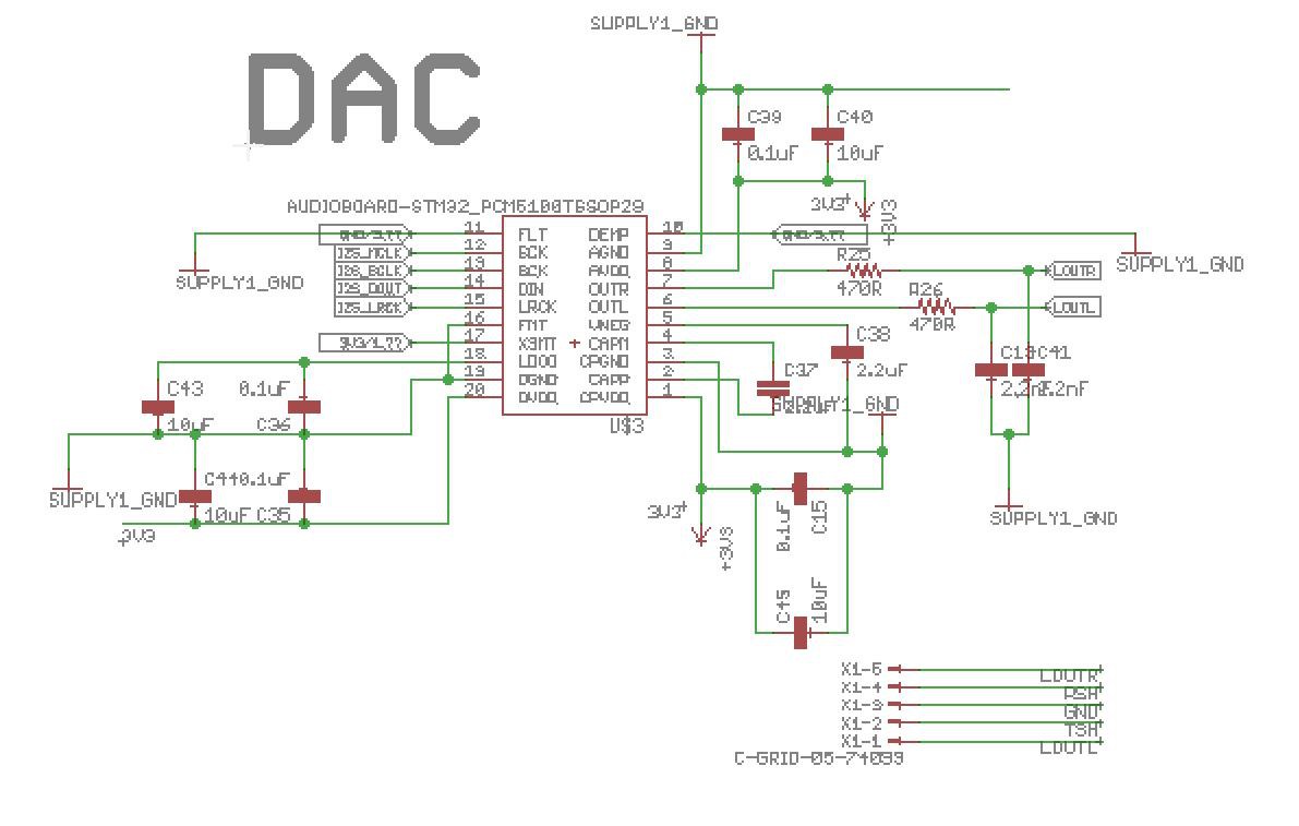
This one is just nuts. The DAC IC was throwing a design rule check error (DRC), so in the course of trying to fix the problem I deleted the part in the schematic, rebuilt the part from scratch and put it back in the schematic. There was still an DRC error and I went about looking for other possible solutions (turns out I had 'highspeed' checked). But the problem was when I replaced the part in the schematic, I put it back rotated 180 degrees. So when I built the board the 3v3 rail was pulled down to 3.24v... odd but not something I was really worried about until the DAC IC heated up to untouchable temps.
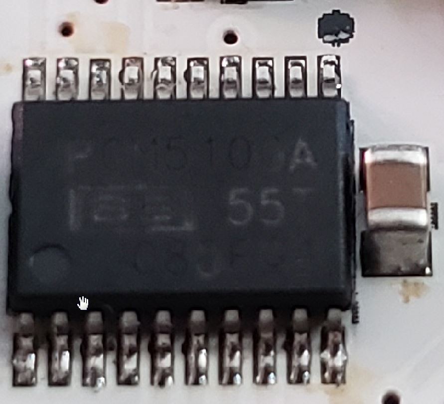
Luckily the board is still usable if I rotate the IC on the board. (Note the pin one mark and the dot on the IC, fun.)
This was also the first time I put a USB-Serial interface on the ball, up to now it has been an off board adapter. When I was testing just a single slice, everything worked great. Once the ball was completely built and I plugged in the ball to my computer, it blew the USB sub systems and reset my monitor (that was a little scary). It seems my computer will let a device try to pull 2.6A from the USB port and then blow a fuse. After a reboot, all was well with the computer. As for the ball, it now has a button that can be pressed at boot to suppress the LEDs, so you can plug it in to your computer for programming. Yay! (If anyone out there knows of a USB hub that does 2.4A and data at the same time please let me know.)
So that was a couple days of frustrating troubleshooting, but as you can see in the video above, it all works, so I'm pretty happy with that.
If you happen to be at Defcon 26, drop by the Tamper Evident Village, I will have a blinky ball there for your viewing pleasure.
Discussions
Become a Hackaday.io Member
Create an account to leave a comment. Already have an account? Log In.
I don't know if all hubs do this, but my cheap Chinese one has little buttons next to the ports. Turning the buttons off disconnects the VCC line, but not the data lines!
So I use it to plug into separately-powered USB projects, and it seems to work well. It's probably doing something terrible internally, but I'm afraid to check.
Are you sure? yes | no
That is both scary and worth looking in to, thanks.
Are you sure? yes | no