 Jurist
So, after my vacation, and some urgent issues at work I'm finally back to my project. :)
I was trying to understand, which approach should I use, to find the reason of non-working combination of PCBAs. The best result gave approach "do everything that could help, and see what happens" :D and then structurize results, adding some calculations! . Fortunately, previous experience in electronics and some brainstorming gave me lot of useful thoughts.
I checked datasheets for LTC IC one more time:

Actually, the result should be more obvious for me at selection stage of this IC, if I made more calculations. I was worrying about that difference in minimum Vin Voltage for different ICs - for LTC it was 20mV. For others it was 80mV. I thought, that this makes a huge difference ( bad intuition!!) in energy. However, I was wrong, and I'll show you how should the correct way of thinking should have been looking like:
1) I desolder the LED from first PCBA, so there is totally no useless energy loss. the output of second PCB still was "quiet"
2) Put more capacitance at first PCBA, because voltage multiplier on it is able to provide up to 2.5 Volts in open-circuit mode. As result, I was able to charge 1000uF capacitor to 1.0 Volts in 30 seconds (!); This was proof, that detector-PCBA is able to collect enough energy without losing it
3) Now I could put previously charged 1000uF capacitor to the second PCBA input. At the same time I was measuring output voltage, where I expected to see more than 2 Volts. Result: Voltage raised a bit, and that's all. Input capacitor was empty too.
4) So.... what was the actual efficiency, when both PCBs were connected ? - obviously, because there was not much current from detector-PCBA, input capacitors all the time were pumped out by LTC chip. If we watch curve above - efficiency at Vin below 200mV is only around 20% (For other transformer rations - even lower, down to 5%!). This correlates with practical results.
5) So, the next question now would be - what efficiecny could provide other ICs?
After analysing TI and Analog Devices ICs, I liked BQ25570 and ADP5092 the most. The first one due its integrated buck-converter, which is beautiful solutions, when there is higher Vin/Vout conversion ration. However, assuming, that Vout should be as low as possible (Bluetooth IC operating Voltage + LDO dropout voltage), calculations showed, that LDO will have same efficiency.
One more feature, that I liked in ADP chip - there is already implemented circuit, I discussed previously: input turns on only after input voltage reaches certain level! (actually, I already modeled one interesting low-power circuit, which activates output, when certain voltage is reached - I'll share it later ;) )
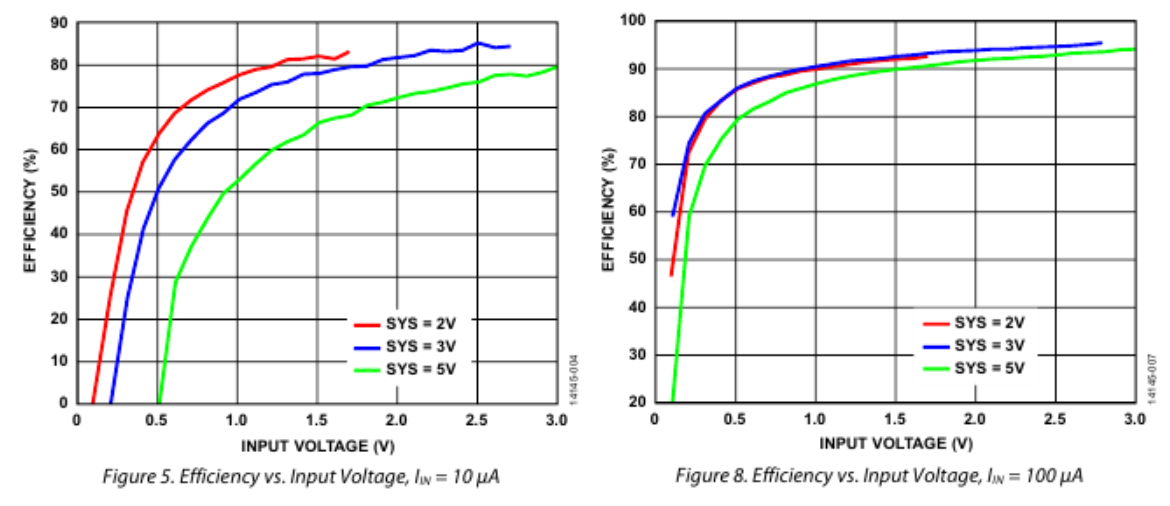
The efficiency graph of ADP5902 was much more promising.
Conclusion: the higher initial voltage of capacitor, when voltage conversion starts, the better efficiency of conversion!!
If we assume, that energy harvesting IC switching starts only after capacitor reaches certain level, we see, that we can reach efficiency up to 90% !!! (Of course, average efficiency during cap discharge will be lower, because Voltage will drop down till 80mV)
6) At this point it's good to know, to which Voltage level 1000uF 1V capacitor is able to charge smaller caps (with, let's say, 70% efficiency); results are following:
330uF => 1.46V
100uF => 2.65V
33uF => 4.61V
Conclusion: we should place as small as possible capacitance at voltage harvester IC output!
7) At this point I started thinking from other side of project: if this energy is enough, to power BLE radio? Some Google-ing showed great Application Note from Texas - http://www.ti.com/lit/an/swra347a/swra347a.pdf, where some numbers were provided. From there I was able to extract, that 1Tx event requires about 75uJ of energy
Calculating the energy, collected by cap: E=C*U^2/2; in our case it's 500uJ.
Considering some conversion loss, we see, that this energy is enough only for 4-5 transmissions.... But we need energy to initialize MCU too!!!
8) Previous point was a bit demotivating for me, because it shows that available energy levels are really low... However, I see, that following steps are able to help with solution:
a. fine-tune detector PCBA. I suspect, it provides only part of energy it is able to detect.
b. change antenna for detector PCBA - try other options
(both steps can be tested experimentally, even without special RF-equipment - just by cutting PCB / adding copper and measuring capacitor voltage :) )
c. Don't forget, that 500uJ were collected at 30s. Assuming, that average mW-oven operating time is several times longer, there is hope! ;)
9) I feel optimistic, and I believe, that there will be some working device if enough effort is put into it!. Therefore, I decided to design new PCBA, based on ADP5901/ADP5902 anyway!!
During design I kept in mind, that it would be cool, to reuse it in other similar projects too, therefore I made the design development-board-like.
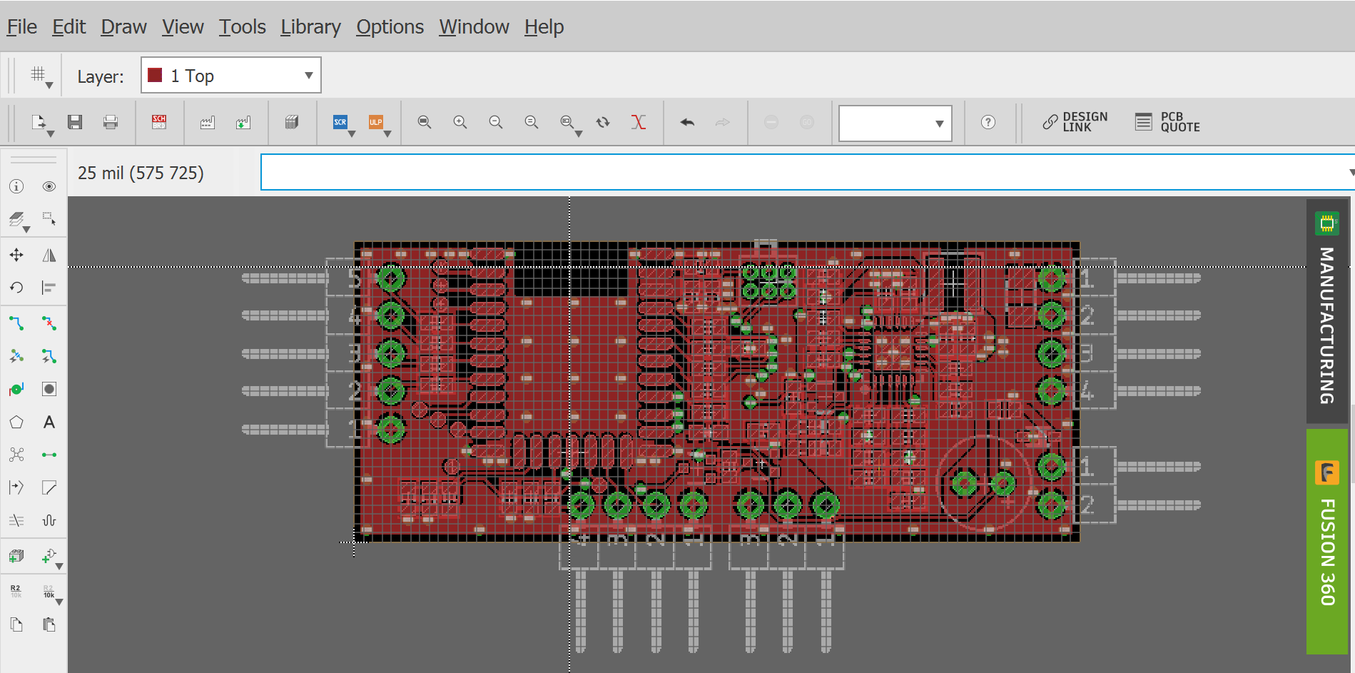
I'll make separate post about the board a bit later, because it's not 100% finished yet.
P.S. So, what is the energy difference, if we leave in cap 20mW or 80mV voltage??
assuming, it's 1000uF, difference is 3uJ (only!!!); for N times smaller cap it will be N times less.....
Discussions
Become a Hackaday.io Member
Create an account to leave a comment. Already have an account? Log In.