 Andrew
Recently I used arduino do digital oscilloscope experiment. It is very interesting through experiment. The programming uses u8g library file that supports multiple LCD displays. There is no need to know how microcontroller works, nor care about the LCD driver, it makes programming very simple.
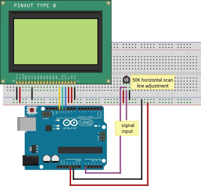
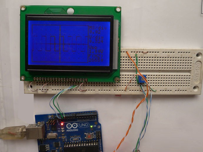
The display used 12864 LCD driven by the ST7920, Arduino is the arduino UNO, here is the circuit diagram (You can redeem it from PCBWay,please support me by register my invited PCBWay link):
The first step:
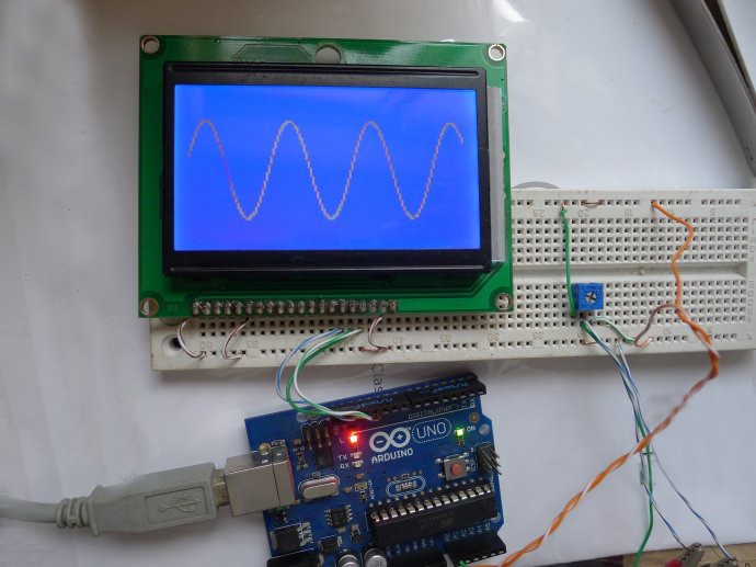
After running the basic code, the waveform of the input signal can be displayed.
Using the ADC inside the microcontroller for digital-to-analog conversion, up to about 1.5KHz input signal can be displayed.
#include <U8glib.h>
U8GLIB_ST7920_128X64_4X u8g(13, 12, 11);
int x,y; int Buffer[128];
void setup( ) { }
void loop( )
{
for(x = 0;x < 128;x++)
Buffer[x] = 63-(analogRead(A0)>>4);
u8g.firstPage();
do
{
for(x = 1;x < 127;x++)
u8g.drawLine(x,Buffer[x],x,Buffer[x+1]); }
while(u8g.nextPage( ));
}
Waveform diagram as shown:
Step 2: Add axes and borders
#include <U8glib.h>
U8GLIB_ST7920_128X64_4X u8g(13, 12, 11);
int x,y; int Buffer[128];
void setup( )
{
analogReference(INTERNAL);
}
void loop( )
{
for(x = 0;x < 128;x++)
Buffer[x] = 63-(analogRead(A0)>>4);
u8g.firstPage();
do
{
for(x = 0;x < 127;x++)
u8g.drawLine(x,Buffer[x],x,Buffer[x+1]);
u8g.drawLine(64,0,64,63);
u8g.drawLine(0,32,128,32);
for(x=0;x<128;x+=8)
u8g.drawLine(x,31,x,33);
for(x=0;x<64;x+=8)
u8g.drawLine(63,x,65,x);
u8g.drawFrame(0,0,128,64);
}
while( u8g.nextPage( ));
}
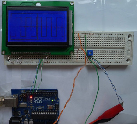
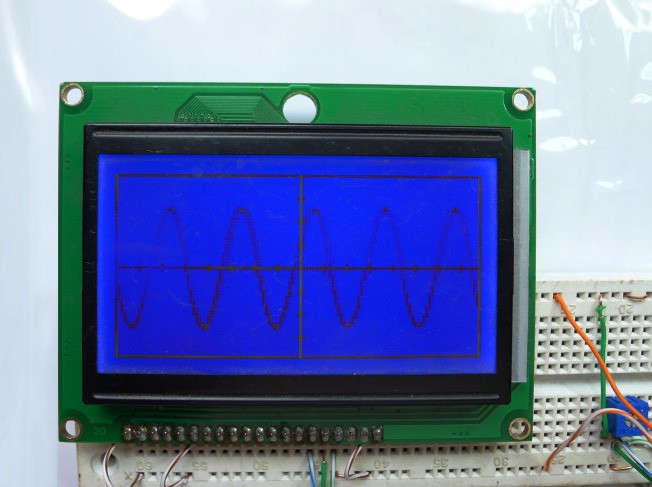
Here is the final version:

 Ahmed Elsaggan
 spark buzzer
 Esmacat
 Lithium ION
this is great. Can you please assist me with "ESP32 based oscilloscope with TFT LCD display", i dont know where to start