 Frederic L
As seen previously each dot is connected to three lines :
- Column SET / RESET is either sourcing current from +24V or sinking current to GND
- Row SET is sourcing current from +24V
- Row RESET is sinking current to GND
So we need to be able to Source Current from the +24V power supply, as well Sink Current to ground, both on the same line in the case of the column trace.
- Source Current with MIC2981 driver
This chip is a 8-channel source driver, it is connected to the power source, it has 8 logic inputs that control 8 high voltage outputs. When an input is HIGH, its corresponding output is sourcing power.
- Sink Current with ULN2803 driver
This is pretty much the same as the MIC2981, except when an input is high, it connects the output to ground and sinks current through it.
- Controlling the drivers with shift registers (SN74HC595)
Several solutions available here, one could use a multiplexer with a binary counter to switch from one row to the next, and from one column to the next, but for more flexibility I chose to control the drivers with shift registers. These will give me a complete control over which columns and row I’m selecting, and in any order, through fast SPI communication. If required I could also flip several dots at the same time, but power will be limited to 500mA for sourcing and sinking from the drivers.
- Quad latch for SET or RESET selection (CD74HC75)
One thing I want to avoid is to shortcut +24V to GND, which could be easily done with a simple mistake in the code such as having both the SET output and RESET output of the micro controller HIGH or LOW at the same time. To avoid this, and reduce the outputs required from the micro controller, I chose to use only one output which would be either HIGH for SET and LOW for RESET. This quad latch splits an input in two opposite signals which will restrict the system to be only in SET mode or only in RESET mode.
- NAND gate for enabling shift registers through pulse control (SN74AS00)
With this setup, the only way to control the pulse of current that goes through the dots is by shortly enabling the output of the shift registers. As we need to select which shift registers we want to switch on (either the ones for SET, or the ones for RESET), we can combine the SET AND PULSE or RESET AND PULSE. OE being active low, a NAND gate instead of AND is appropriate.
- Power sources
For the power supply, I will start with a MeanWell LRS 150-24, an open frame PSU probably overkill with 150W of power. I’ll select a final PSU when I’ll have figured how much power I need to run the display.
For the low voltage power, I found a small cheap adjustable switching PSU circuit on eBay, which offers variable output including 3.3V for the ESP or 5V. All ICs mentioned above are compatible with 3.3V or 5V inputs.
- Logic subtlety and controller available modes
If you look closely at the schematic, you'll notice that the columns sink drivers associated shift registers (bottom left) are not enabled through the SET_PULSE line as we could expect, but instead directly from the RESET line, bypassing the NAND gate. This is due to the design of the LEDs on the ANNAX display.
The LEDs have their anode connected to the shift registers on the display itself (controlled independently), and their cathodes are connected to the columns SINK lines. Therefore, when I'm not flipping dots (PULSE line LOW), I still need to enable the columns sink lines to control the LEDs, independently of the PULSE input.
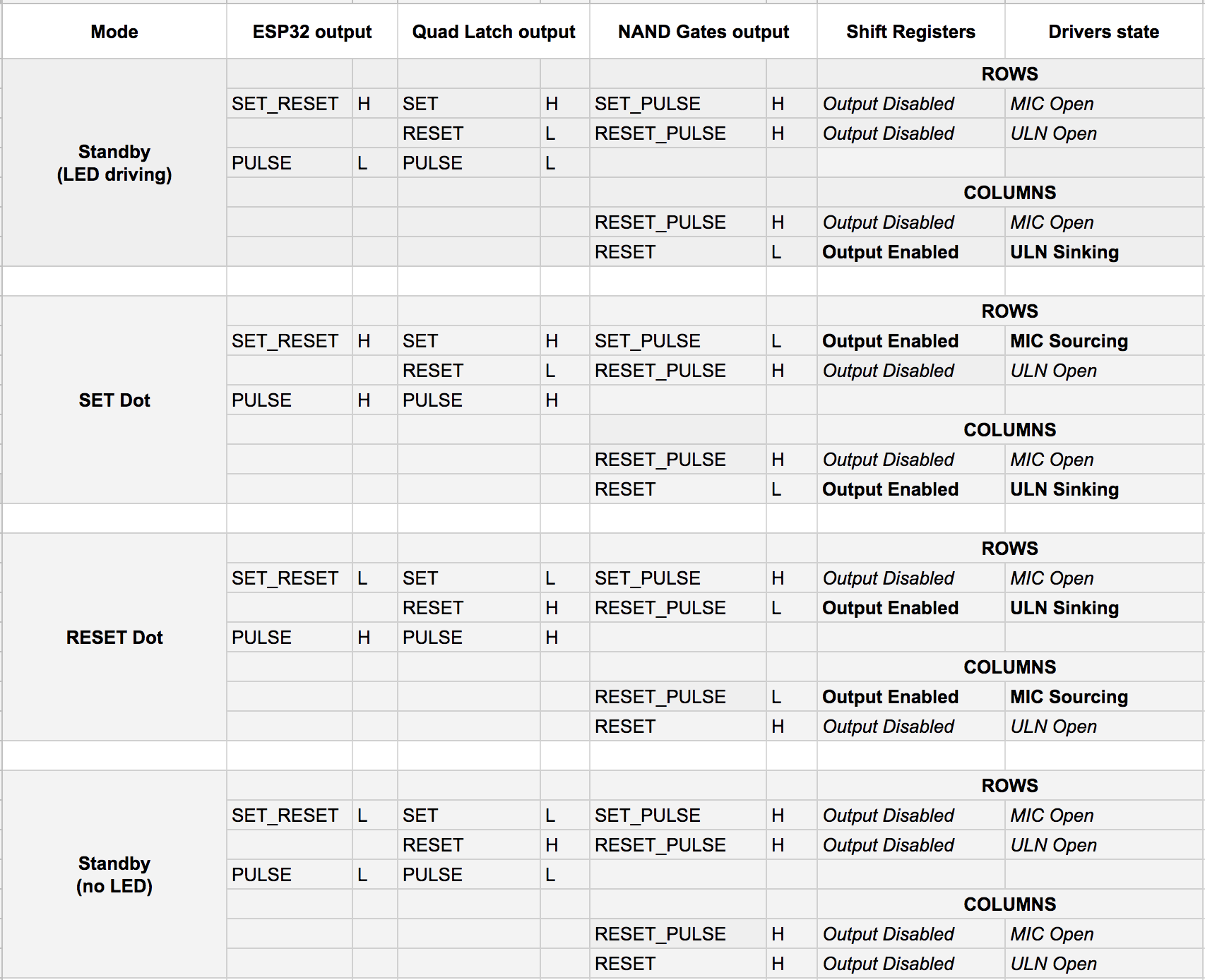
Here is a table with the 4 different modes the controller can be according to the state of the SET_RESET and PULSE output lines of the micro controller :
Discussions
Become a Hackaday.io Member
Create an account to leave a comment. Already have an account? Log In.