 Frederic L
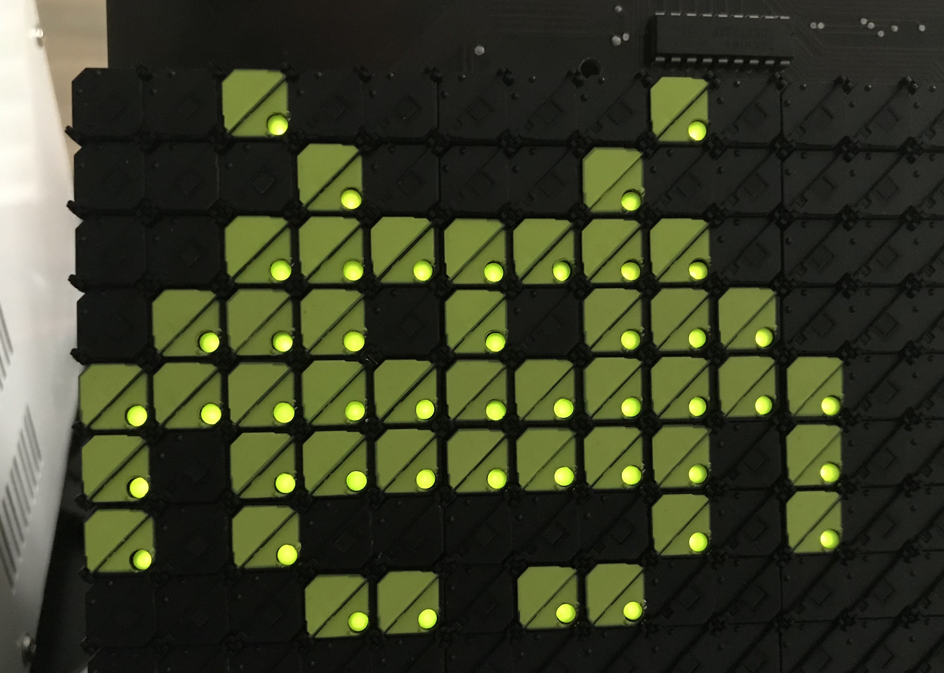
Finally, I made some steps forward following the little setback of previous log. After the smoke, comes the glow :)
After a couple of weeks unsuccessfully trying to chain the displays together, I thought I'd try something different : attempt to drive the LEDs of the dots. It took me the whole day, but it does work pretty nicely !
As described previously when taking a close look at the ANNAX display, all 16 rows of LED anodes are connected to two 8ch source driver controlled by two 8 bits shift registers. Those 4 chips are integrated onto the display.
The LED cathodes are linked per columns and connected to the flipdots column sink drivers (on my controller).
So in order to drive the LED we need to go through each columns one by one, load the 16 bits representing each 16 dots state for that column, illuminate the LEDs, move onto the next column, and repeat. If done fast enough, we don't see the blinking and the illumination feels quite natural. The flickering on the video is from the camera and isn't visible to the naked eye.
Now the code is a bit more complex as I used my updated code and functions that I'm continuously tweaking and improving for broader usage.
Basically there are two important variables : current_display[] and new_display[].
Both are array of bits (30x16) representing the current and requested state of the display.
Any modification to the display is done on the new_display[] array, then the code compares the current state and requested state of the display, and only the necessary dots are being flipped and unflipped.
The rest is commented, but feel free to ask if you have questions.
#include <Arduino.h>
#include <SPI.h>

// SPI pins for sending data into shift registers
#define SPI_SPEED 1000000  // 1 Mhz
#define PIN_CS_ROW 10 //22
#define PIN_CS_COL 9 //21
#define PIN_RST_ROW 8 //2
#define PIN_RST_COL 7 //0

// Pins used for flipping dots
#define PIN_SET_RESET 6 //4
#define PIN_PULSE 5 //15

// Pins for LED control
#define PIN_LED_OE 3 // PWM PIN
#define PIN_LED_STR 2

// Fixed parameters
#define PULSE_LENGTH_US 200  // May be adjusted according to voltage used
#define SET 1  // HIGH
#define RESET 0  // LOW

// Display params
#define DISPLAY_WIDTH 30  // Only 1 display connected for now
#define DISPLAY_HEIGHT 16

uint16_t current_display[DISPLAY_WIDTH];
uint16_t new_display[DISPLAY_WIDTH];

// 8bit Space Invader
const unsigned char monster8x11[] = {
  0b01110000,
  0b00011000,
  0b01111101,
  0b10111110,
  0b10110100,
  0b00111100,
  0b10110100,
  0b10111110,
  0b01111101,
  0b00011000,
  0b01110000
};


void clear_registers(){
  // Clear Shift Registers
  // I have doubt if this is working as datasheet is confusing

  digitalWrite(PIN_RST_ROW, LOW);
  digitalWrite(PIN_RST_COL, LOW);
  delayMicroseconds(1);
  digitalWrite(PIN_RST_ROW, HIGH);
  digitalWrite(PIN_RST_COL, HIGH);
}


void load_single_dot(uint8_t x, uint8_t y){
  // This method safely pre-loads all SR with zeros and only 1 bit set at the
  // requested x and y position.

  // Currently this method is implemented for
  // 2 horizontally daisy chained 30x16 displays (2x1)
  //  ______________________________    ______________________________
  // |                              |->|                              |
  // |         DISPLAY 1            |->|         DISPLAY 2            |
  // |         (30 x 16)            |->|         (30 x 16)            |
  // |                              |->|                              |
  // |______________________________|->|______________________________|
  //
  // Any other arrangements "3x1" displays or "2x2" or "1x2" are possible,
  // but modifications have to be made in the order of bytes of data
  // sent to the registers and number of bytes sent to accomodate for each
  // individual setup and how shift registers are connected
  // (vertically vs horizontally). 25 dots width displays can be used as well.

  // Clear shift register data, but if it doesn't work it's not a problem
  // as we send bytes to all SR of the two controllers.
  clear_registers();

  // Insert 2 dummy bits for unused output 31 and 32 of shift registers
  // in the case of a 30 dots wide display with a controller of 4 SR (32 bits)
  // May have to be adjusted if using a 25 dots wide display with 4 SR.
  if(x >= 30) {
    x+=2;
  }

  // Initialise SPI communication
  SPI.beginTransaction(SPISettings(SPI_SPEED, MSBFIRST, SPI_MODE0));

  // COORDINATE X :
  digitalWrite (PIN_CS_COL, LOW);  // Slave Select Columns shift registers

  for(int b=7; b>=0; b--){
    // Transfer as many bytes as number of column SR on all controllers (8)
    if((int) (x/8) == b){
      // Transfer a 1 into the correct position of correct SR
      SPI.transfer(0x01 << (x%8));
    } else {
      // Transfer 0s to other SR to blank any remaining other data
      SPI.transfer(0x00);
    }
  }

  // End Slave Select Columns
  digitalWrite (PIN_CS_COL, HIGH);


  // COORDINATE Y :
  digitalWrite (PIN_CS_ROW, LOW);  // Slave Select Rows shift registers

  if(x>=32) {
    // Targeting display 2, so we increase y by 16 to address its SR
    y += 16;
  }

  for(int b=3; b>=0; b--){
    // Transfer as many bytes as number of row SR on all controllers (4)
    if((int) (y/8) == b){
      // Transfer a 1 into the correct position of correct SR
      SPI.transfer(0x01 << (y%8));
    } else {
      // Transfer 0s to other SR to blank any remaining other data
      SPI.transfer(0x00);
    }
  }

  digitalWrite (PIN_CS_ROW, HIGH);  // End Slave Select Rows


  SPI.endTransaction();  // End SPI

}

void flip(bool dir, int delay_ms=1) {
  digitalWrite(PIN_SET_RESET, dir);
  delayMicroseconds(1);

  // Send pulse
  digitalWrite(PIN_PULSE, HIGH);
  delayMicroseconds(PULSE_LENGTH_US);
  digitalWrite(PIN_PULSE, LOW);

  // Revert to SET/RESET HIGH to allow for LED on
  digitalWrite(PIN_SET_RESET, HIGH);
}

void update_display() {
  // Compare new_display[] and current_display[]
  // Dots are flipped or unflipped only where necessary.
  // Once display updated, current_display = new_display, ready for next update.

  clear_registers();
  uint16_t to_change = 0x0000;

  // For each columns
  for(int col = 0; col<DISPLAY_WIDTH; col++){
    // Isolate dots to RESET
    to_change = current_display[col] & ~new_display[col];
    for(int row = 0; row<16; row++) {
      if(bitRead(to_change, row)) {
        load_single_dot(col, row);
        flip(RESET);
      }
    }

    // Isolate dots to SET
    to_change = ~current_display[col] & new_display[col];
    for(int row = 0; row<16; row++) {
      if(bitRead(to_change, row)) {
        load_single_dot(col, row);
        flip(SET);
      }
    }
  }

  //current_display[] = new_display[];
  memcpy(current_display, new_display, sizeof(current_display));
}

void draw_monster_icon(int x, int y) {
    for(int i=0; i<11; i++){
      new_display[i+x] |= monster8x11[i] << y;
  }
}

void clear_display(){
  for(int i=0; i<DISPLAY_WIDTH; i++){
    new_display[i] = 0x0000;
  }
}

// Animate monster
int pos_x = 0;
int pos_y = 0;
int h = 1;
int v = 1;
int max_x = 19;
int max_y = 8;
unsigned long last_frame = 0;

void animate_monster(int rate_ms = 1000) {

  if(millis()-last_frame > rate_ms){
    // Time to update animation
    clear_display();
    draw_monster_icon(pos_x,pos_y);
    update_display();

    last_frame = millis();

    // next coordinates :
    pos_x += h;
    pos_y += v;

    if(pos_x >= max_x){
      h = -1;
    }
    if(pos_x <= 0){
      h = 1;
    }

    if(pos_y >= max_y){
      v = -1;
    }
    if(pos_y <= 0){
      v = 1;
    }
  }

}

// LED led driving
void led_driving() {
  // For each column, illuminate flipped dot LED

    for(int col = 0; col<DISPLAY_WIDTH; col++) {
      load_single_dot(col, 0); // load column in COL SR, and any row.

      SPI.beginTransaction(SPISettings(SPI_SPEED, LSBFIRST, SPI_MODE0));

      // ROW
      digitalWrite (PIN_LED_STR, HIGH);  // Slave Select LED Rows
      SPI.transfer(current_display[col] >> 8); // Lower part of screen
      SPI.transfer(current_display[col]); // Top part of screen
      digitalWrite (PIN_LED_STR, LOW); // End Slave Select LED Rows
      SPI.endTransaction();  // End SPI

      analogWrite(PIN_LED_OE, 255); // LED BRIGHTNESS 0 = OFF; 255 = MAX
    }
}


void setup() {
  // Defining outputs
  pinMode(PIN_CS_ROW, OUTPUT);
  pinMode(PIN_CS_COL, OUTPUT);
  pinMode(PIN_RST_ROW, OUTPUT);
  pinMode(PIN_RST_COL, OUTPUT);
  pinMode(PIN_SET_RESET, OUTPUT);
  pinMode(PIN_PULSE, OUTPUT);

  pinMode(PIN_LED_OE, OUTPUT);
  pinMode(PIN_LED_STR, OUTPUT);

  // Initial outputs state
  digitalWrite(PIN_CS_ROW, HIGH);
  digitalWrite(PIN_CS_COL, HIGH);
  digitalWrite(PIN_SET_RESET, LOW);
  digitalWrite(PIN_PULSE, LOW);

  digitalWrite(PIN_LED_OE, LOW);
  digitalWrite(PIN_LED_STR, LOW);

  // Clear Shift Registers
  clear_registers();

  SPI.begin();

  delay(5000);
}


void loop() {

  animate_monster(1000);
  led_driving();

}
Strangely, I didn't have to provide extra power to the LED as the integrated voltage regulator seems to be able to provide enough current to make the nice glow shown above. The brightness can be increased if needed by plugging +5V on the display TAB connector, and then adjusting the PWM output value in the code.
The only thing left now is to figure out how to chain displays (seems easy on paper, but can't make it work so far), and once this works I will move onto designing the final control board.
Discussions
Become a Hackaday.io Member
Create an account to leave a comment. Already have an account? Log In.