 Lucy Fauth
Another interesting aspect about this phased array design is the power management.
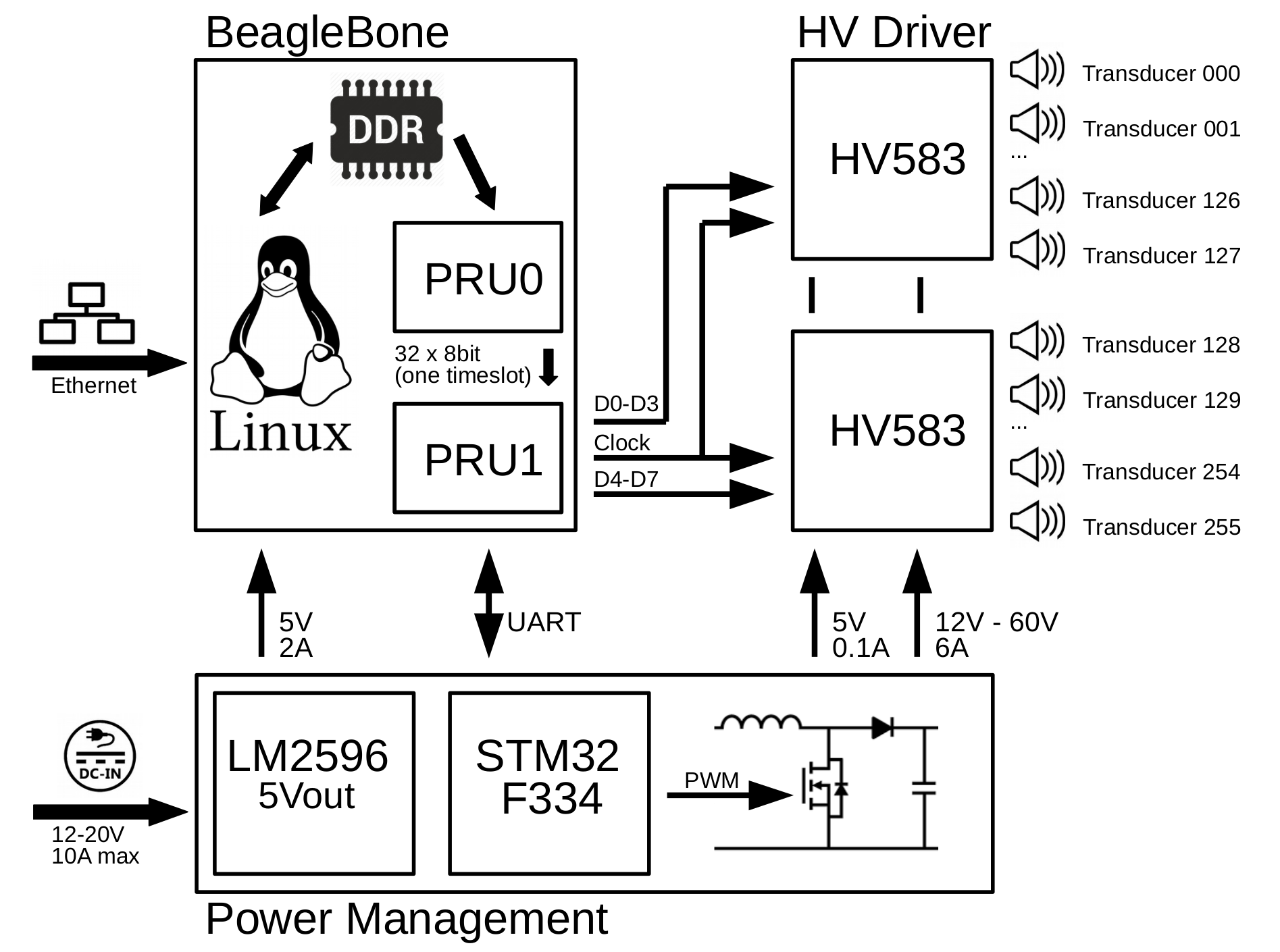
While the BeagleBone is rather easy to power (it only requires 5V 2A), the main array requires a voltage of 12V – 80V. This voltage down not necessarily need to be adjustable, but it realy helps for testing to start out with a lower power. Also, for levitation applications, it is simpler to adjust the output power via the supply voltage then to change it via the phase pattern.
Designing digitally adjustable power supplies is always rather annoying. It’s not a typical application, so there are few ready-to-use chip designs available on the market. The probably most popular way is to use a standard off-the-shelf switching mode controller, and adjust the output voltage on the fly by modifying the feedback resistor network either with a digital potentiometer, or with a programmable amplifier. First off this is rather a workaround than a recommended solution, and you can get lots of problems with this design (the whole system can get unstable and start oscillating).
That’s why I decided to implement this switching mode controller all in software. I’m a big fan of the STM32 ARM processors by STMicro, and one part that is particularly interesting is the STM32F334. This microcontroller contains a high resolution timer (and by high resolution, we are talking about 217ps) and some other very useful analog peripherals. This timer allows me to generate two PWM signals, one inverted and with dead time, that have a frequency of 600kHz and a resolution of >12 bit. Every 128th period, the ADCs that measure output voltage and current are sampled and a simple PI regulator with current feedforward adjusts the duty cycle of the PWM. The signal goes straight to a half-bridge gatedriver + MOSFETs that form a synchronous boost converter. The setpoint of this regulator can be adjusted in software, and in this project the STM32 is connected to the BeagleBone via UART to set the output voltage. The serial wire debugging port is connected to the BeagleBone as well to allow flashing the STM without a designated debugger, using a port of OpenOCD.
I could write a
whole article about software-defined switching mode power supplies. This is super useful
and handy and totally underrepresented in the community. For example, this
STM cost 2.80$ and does do job of a 4$ proprietary SMPS IC. Anyway,
for now if you’re interested in how exactly this works, take a look
at the firmware on github: https://github.com/ultrasonic-phased-array/array-V3-stm32
Apart from the power management, the STM32 also serves some more purposes. The problem with the transducers I want to use is that the polarity is unknown. That is because for most applications of ultrasonic transducers, the phase of the wave doesn’t matter. You can get them with a polarity marking, but that cost like 200% extra (40ct the transducer, another 70ct for the branding…). For array V2 I did this measurement myself, by applying a sine wave with known phase and measuring the ultrasonic output with a seconds transducer at a known distance. This was a lot of work (in the order of 3-4h) and I don’t want anyone to go through the same struggle. Also, you need at least a signal generator and a scope, and I want this project to be as accessible as possible even for beginners.
That is why for this version, I wanted to implement an “auto-learn” function: The BeagleBone switches on one transducer at a time, it scans over all 256 transducers in something like 100ms.
Now you take a separate transducer that acts like a receiver that is connected to the array. You slowly move it over the surface of the array, and a GUI shows you what area you have already covered. Due to the scanning, the BeagleBone knows exactly which transducer you are currently receiving. Given a fixed distance to the array (like, for simplicity, 0mm ;) the BeagleBone can calibrate the phase and the amplitude for each transducer and use that data to correct these parameter in software. This allows you to randomly solder in the cheap transducers without worrying about their polarity.
This is where the analog pheripherals of the STM32 come in handy: A comparator inside the microcontroller is used to detect the zero crossing of the received sine wave. Optionally, if the signal is too weak, it can be amplified by up to x16 by an internal PGA. The edge of the signal is then compared to the signal of Transducer number 0 which is used as the global phase reference. Also, an ADC channel measures the envelope voltage of the signal. Data is sent to the BeagleBone via UART which manages the whole calibration procedure.
The schematic isn’t
particularly interesting. If you want to check it out anyway, you can
find the schematic as a pdf on github: https://github.com/ultrasonic-phased-array/array-V3-hardware/blob/master/array.pdf
Discussions
Become a Hackaday.io Member
Create an account to leave a comment. Already have an account? Log In.